Guillermo Perez Guillen
-
13. Summary and Report Updated
10/05/2022 at 02:27 • 0 commentsSummary
Below, I show you the project wrap-up and lessons learned of this cost-effective solution:
Getting Started
Here I describe the technical characteristics of the Arduino MKR WAN 1300 board, the installation of the board in the Arduino IDE application, as well as the firmware update. Finally we test the Blink.ino demo code to check if the boards are working fine.
![]()
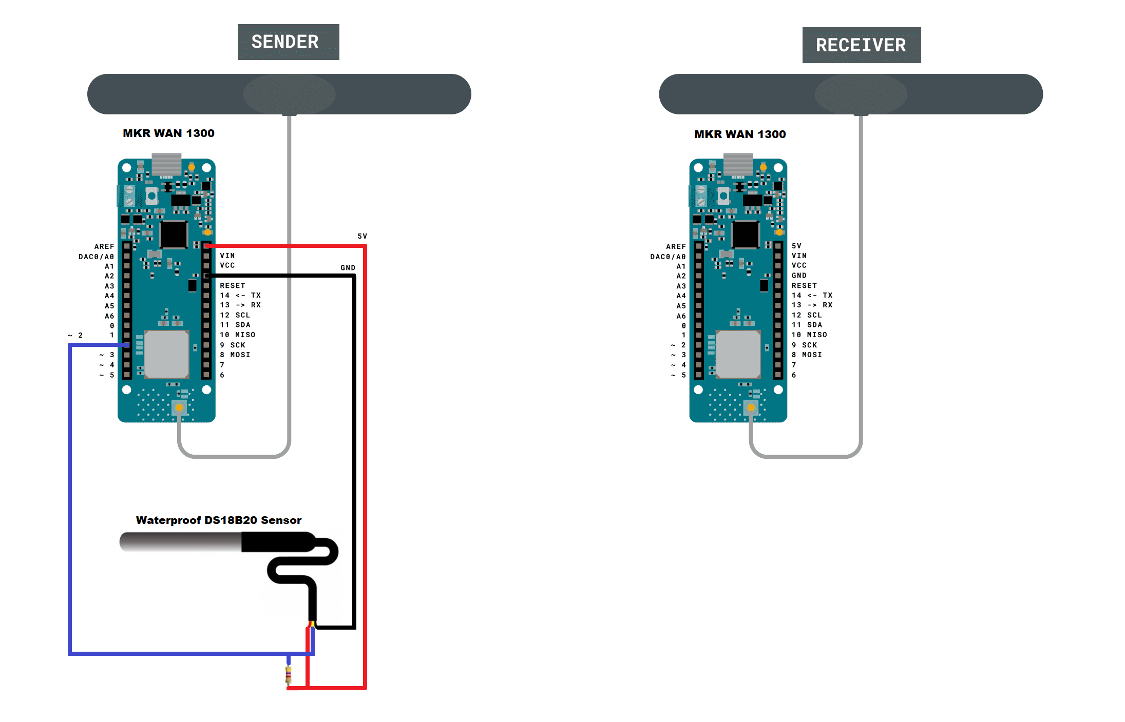
Communication Between Two MKR WAN 1300
Here we start with the most basic, which is the point-to-point communication between two Arduino MKR boards. The transmitter sends data from the Waterproof DS18B20 sensor, and every time the receiver receives data, an LED on the board flashes and the serial port shows us the temperature of the sensor.
![]()
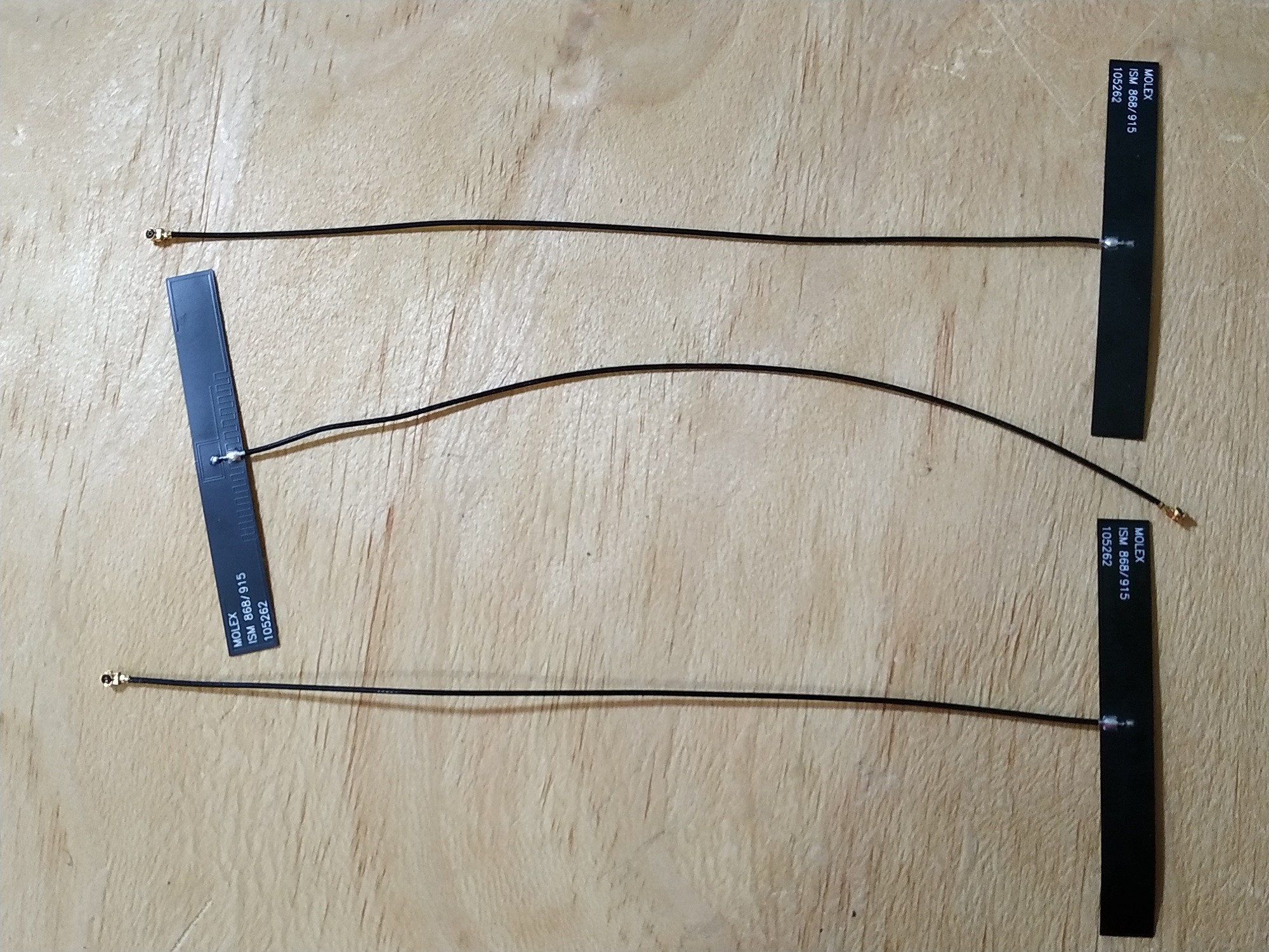
LoRaWAN System Range Testing
The next test is to check the link quality between the transmitter and receiver. So I make a comparison between different RF antennas, and finally the ones that showed the best performance are the manufacturer's dipole antennas. It is important to take care of this detail to avoid bad RF communication or corrupt messages.
![]()
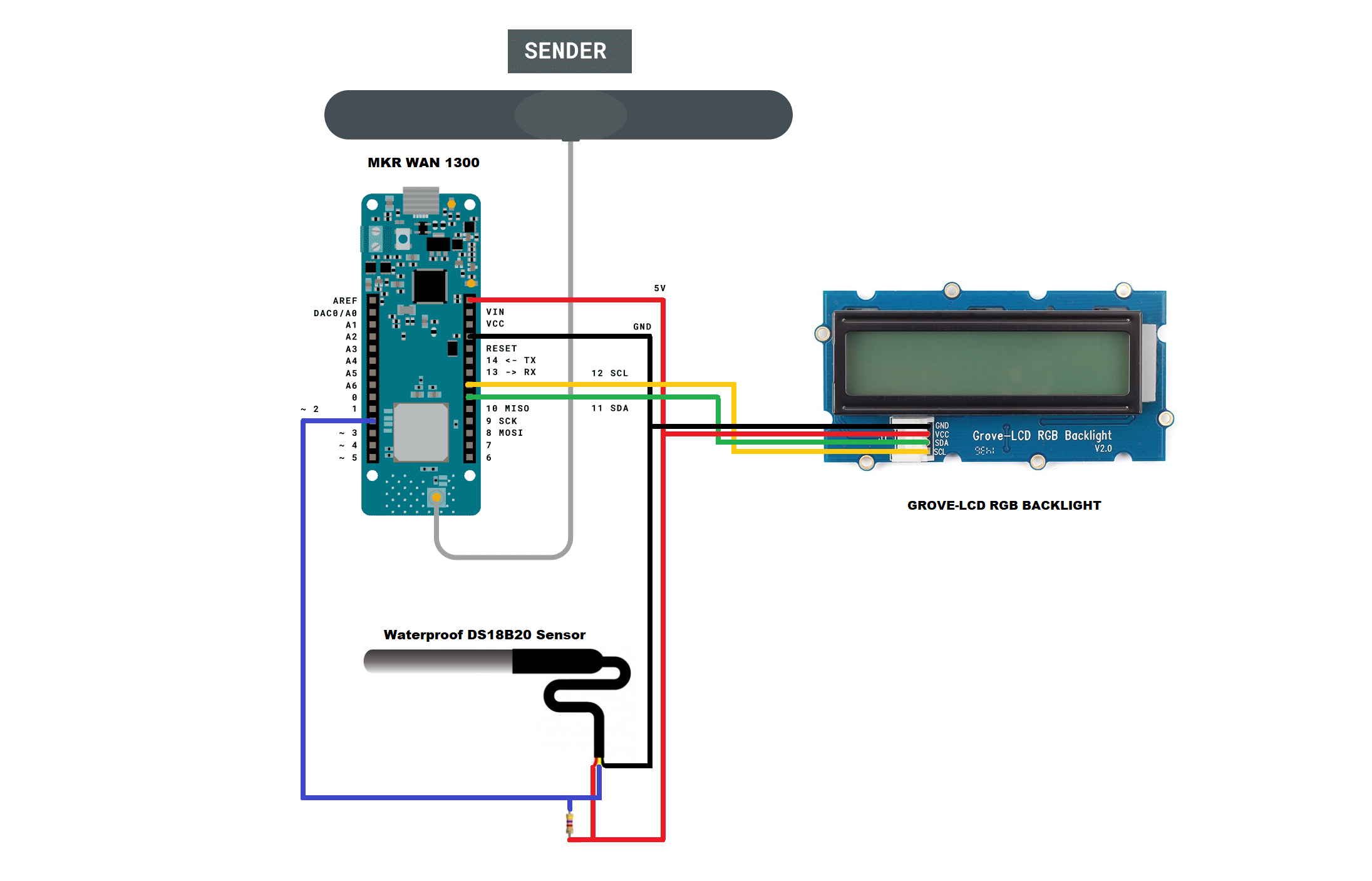
Assembling the Transmitter
It’s time to assemble the transmitter module and add a LCD display to it. Here I have used the case and the Grove-LCD RGB Backlight, and the assembly steps can be found in this tutorial.
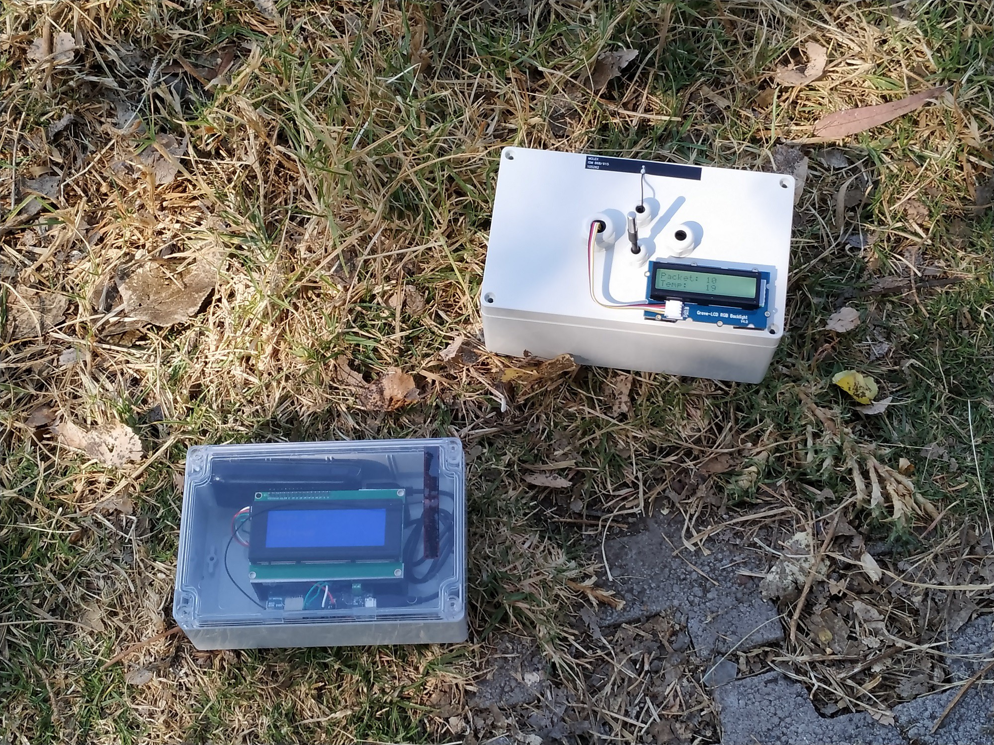
Assembling the Receiver, and LoRaWAN´s Field Test with a DS18B20 Sensor
I have also added the steps to assemble the receiver module with a 20x4 LCD display in this section as shown in the image below. Once we have assembled the LoRaWAN transmitter and receiver modules, its time to test them in the field. As a preliminary test, I did hardware and software verification before going out to the field.
![]()
Adding Multiple Sensors: DS18B20, DHT22 and MQ-135
We still continue with the point-to-point links between two Arduino MKR WAN boards, but this time we will do it with multiple sensors. I have added the DHT22 humidity sensors and the MQ-135 air quality sensor to the transmitter module. Here I have used a method to join the data using the comma character.
Modifying Receiver Code for Multiple Sensors, and LoRaWAN´s Field Test with Multiple Sensors
Here I show you how to modify the code of the receiving module to separate the data from multiple sensors and display them on the 20x4 LCD display. All by using code and the comma character to separate the data. Once we have assembled the LoRaWAN transmitter and receiver modules using multiple sensors, it´s time to test them in the field. Also, as a preliminary test, I did hardware and software verification before going out to the field.
![]()
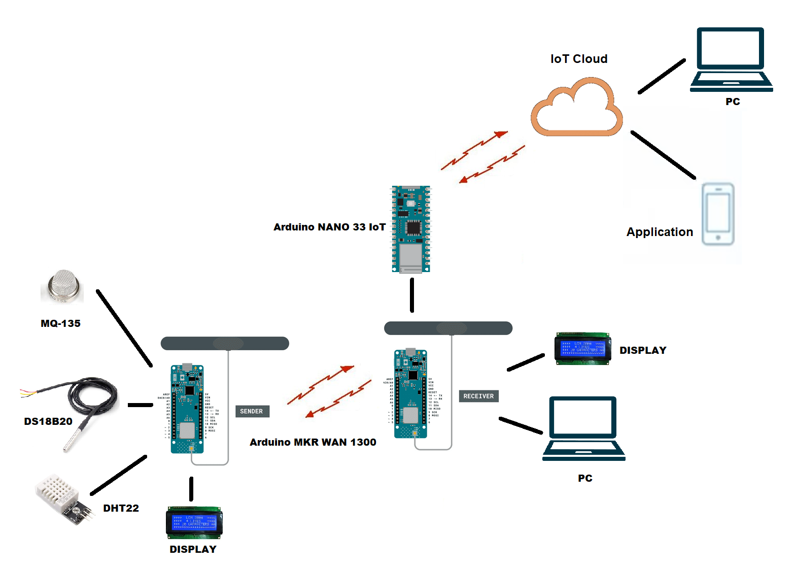
How to Connect LoRaWAN to an IoT Provider through the Arduino NANO 33 IoT
In this section I show you a cheapt way to make an IoT connection with our Arduino MKR WAN 1300 boards. That is, through the Arduino NANO 33 IoT board. Here I show you the theoretical information and the reference that supports me.
LoRaWAN and IoT Connection
Here I show you the changes that must be made in hardware and software to achieve the connection to an IoT provider, and using a multiple sensors. I have modified the code of the receiver module to connect it to the Arduino NANO 33 IoT board taking into account the explanation that I showed you in the previous chapter. I also show you the code of the Arduino NANO 33 IoT board to connect to the ThingSpeak IoT provider, but you can do it with any other IoT provider. We have several options to monitor this data: a) on the display of the transmitter and receiver module, b) on the PC connecting to the ThinSpeak shared channel, and c) through the Android Application ThingView.
![]()
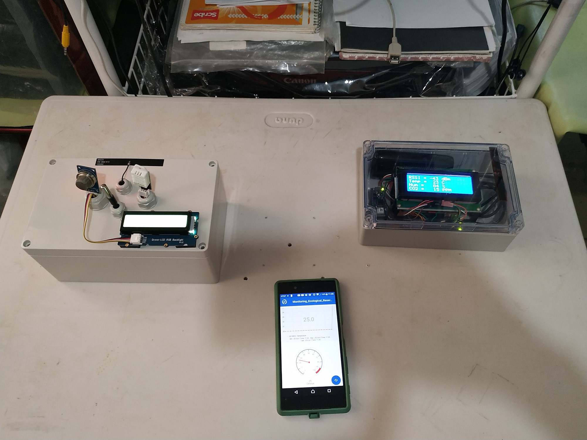
Testing LoRaWAN and IoT Connection
In the final chapter we can see the hardware and software verification tests, as well as the field tests. This was a good experience since I learned to improve the quality of the signal by placing the transmitter module in different trees until getting the best reception.
![]()
What next for this project?
The next challenge is to add more features as shown below:
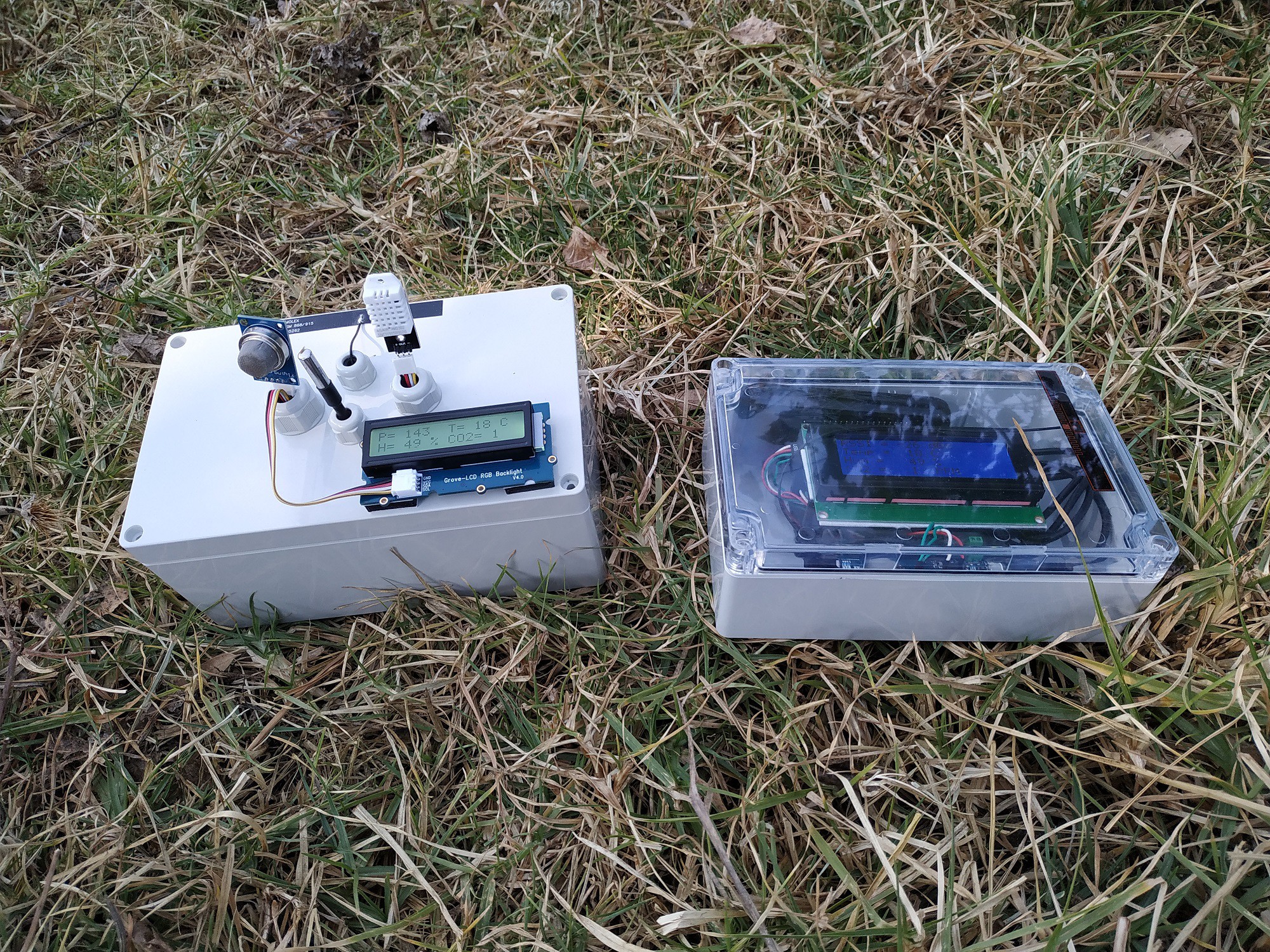
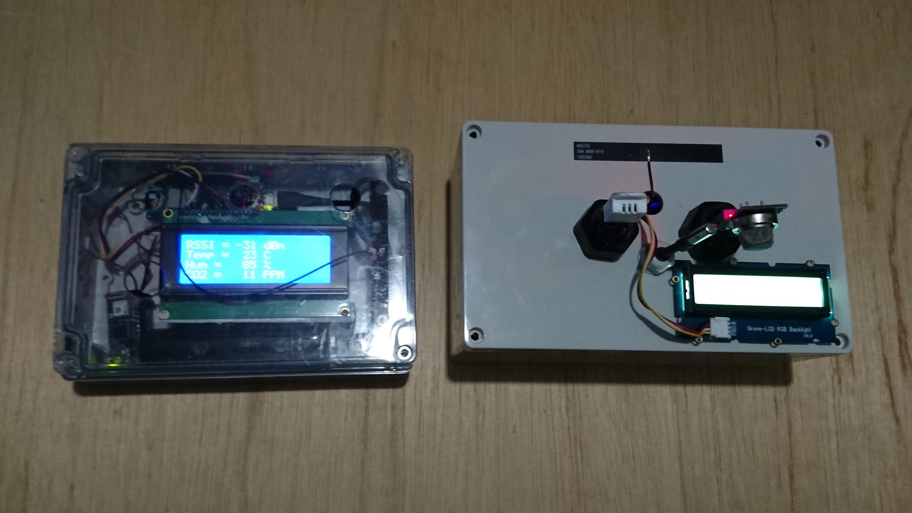
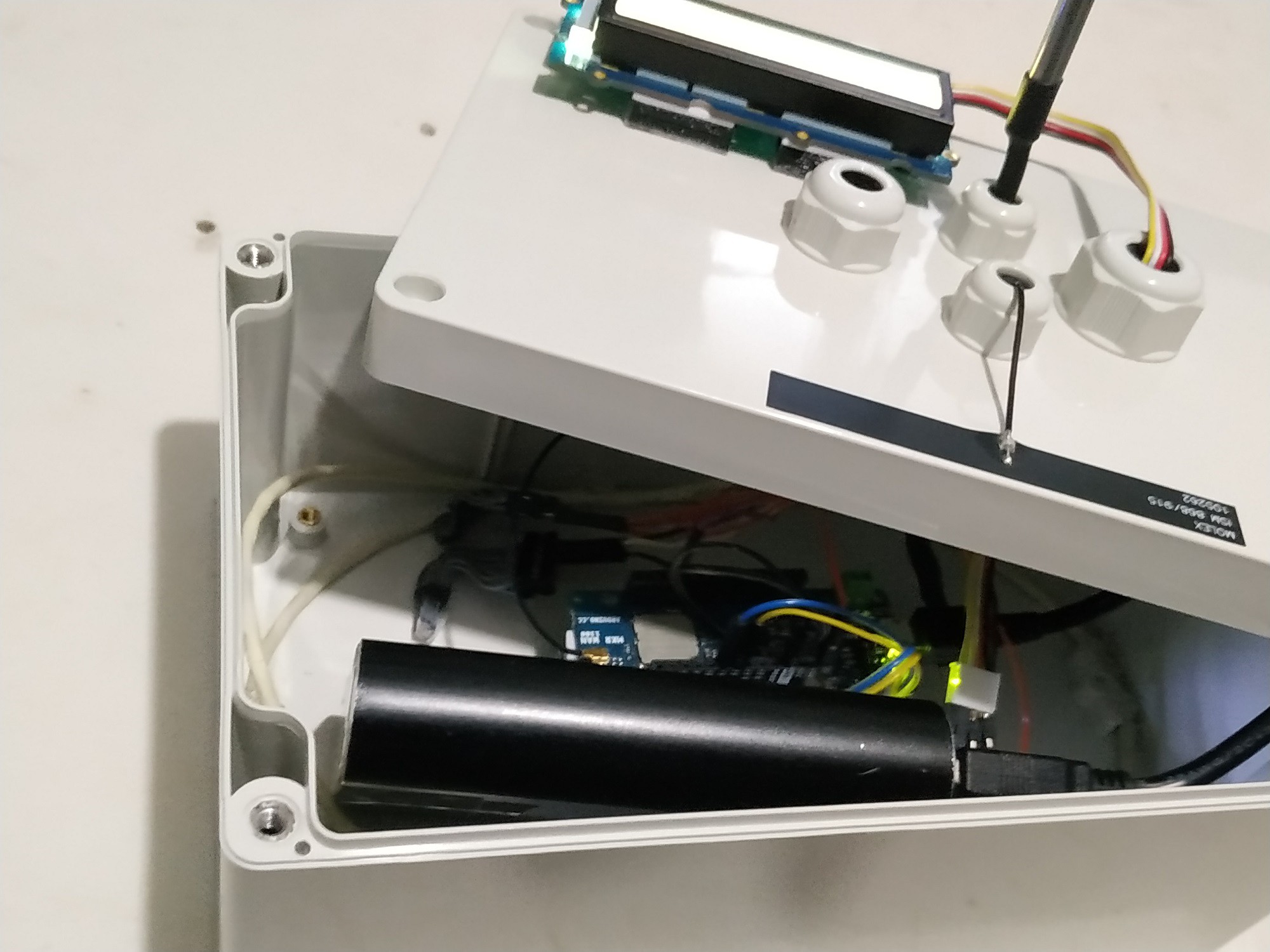
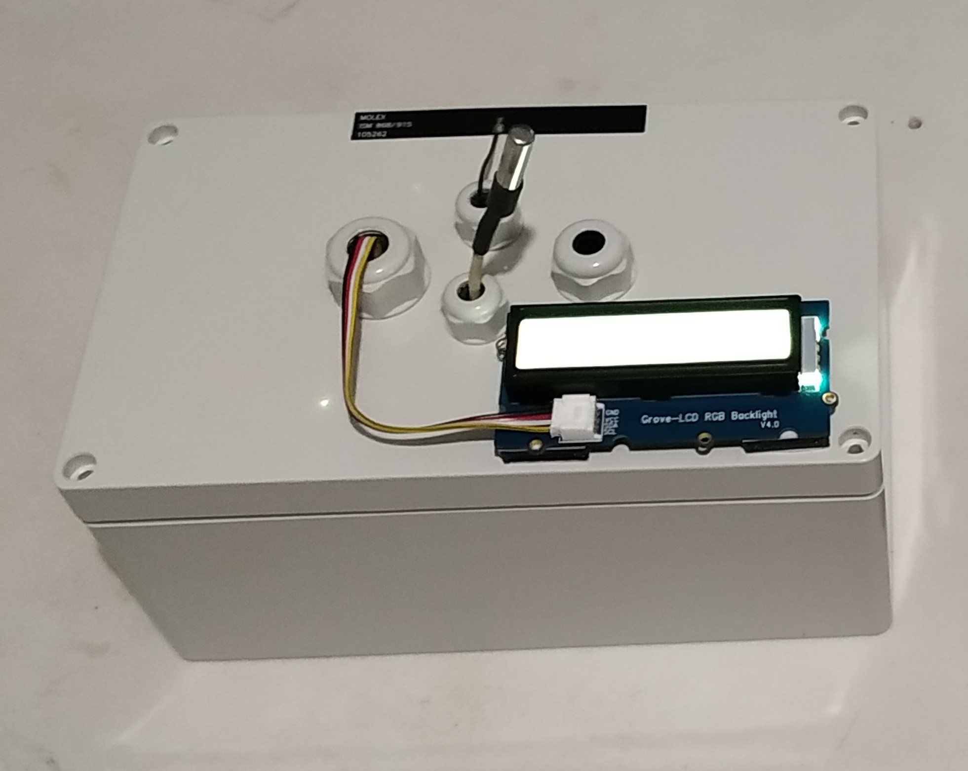
- I have reorganized the transmitter and receiver modules in order to make their work more efficient. In the transmitter module I needed a larger space to connect the solar panel, and anso not bend the antenna too much and avoid the risk of disconnecting it, so I removed the "cable gland", I have also replaced the "cable glands " of the DHT22 and MQ135 sensors for the ones with a larger diameter in order to place here the future sensors that I'm going to add. In the receiver module I have rearranged the programming boards in order to add a higher power battery, I have also added some holes to make connections to the outside either for power supply or for a connection to a PC.
![]()
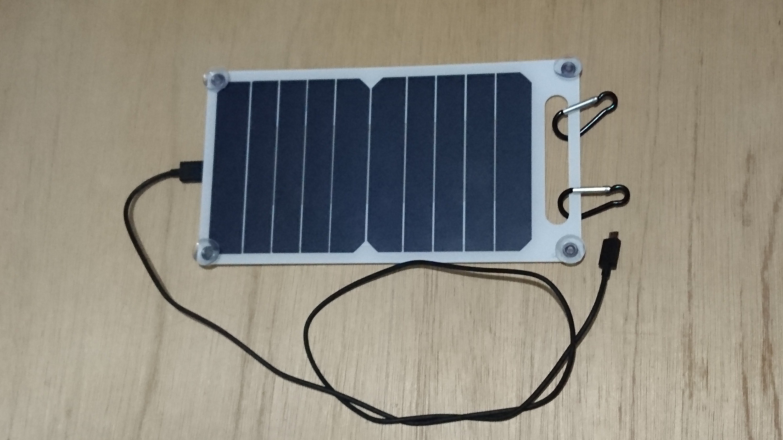
- I'm trying to adapt a solar cell to recharge the battery when the system is on standby mode. Until October 20, I received a 10 watt solar panel charger (Output: USB 5V, 1200mA) by courier. It's ideal for recharging the transmitter battery and doing charging tests.
![]()
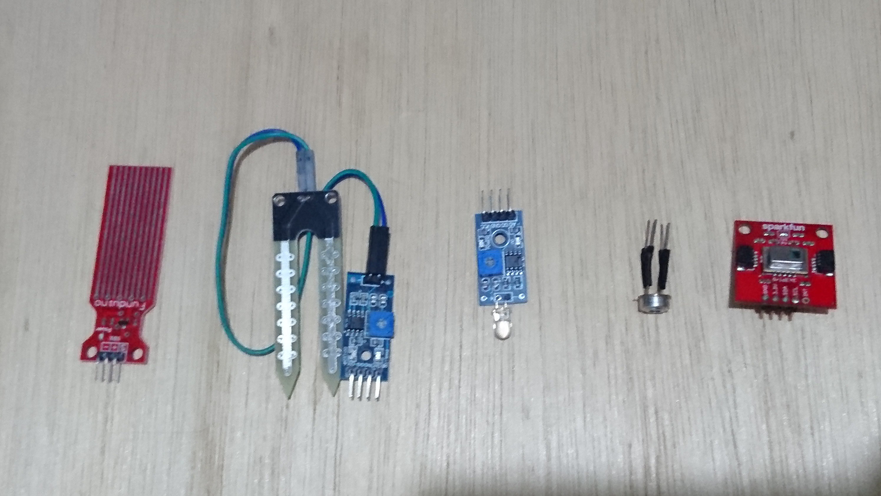
- I'm tryng to add as many sensors to the transmitter module as possible. For example, also I received next sensors: water sensor, soil moisture sensor, flame sensor, Infrared Thermometer - MLX90614, and Infrared Array - AMG8833.
![]()
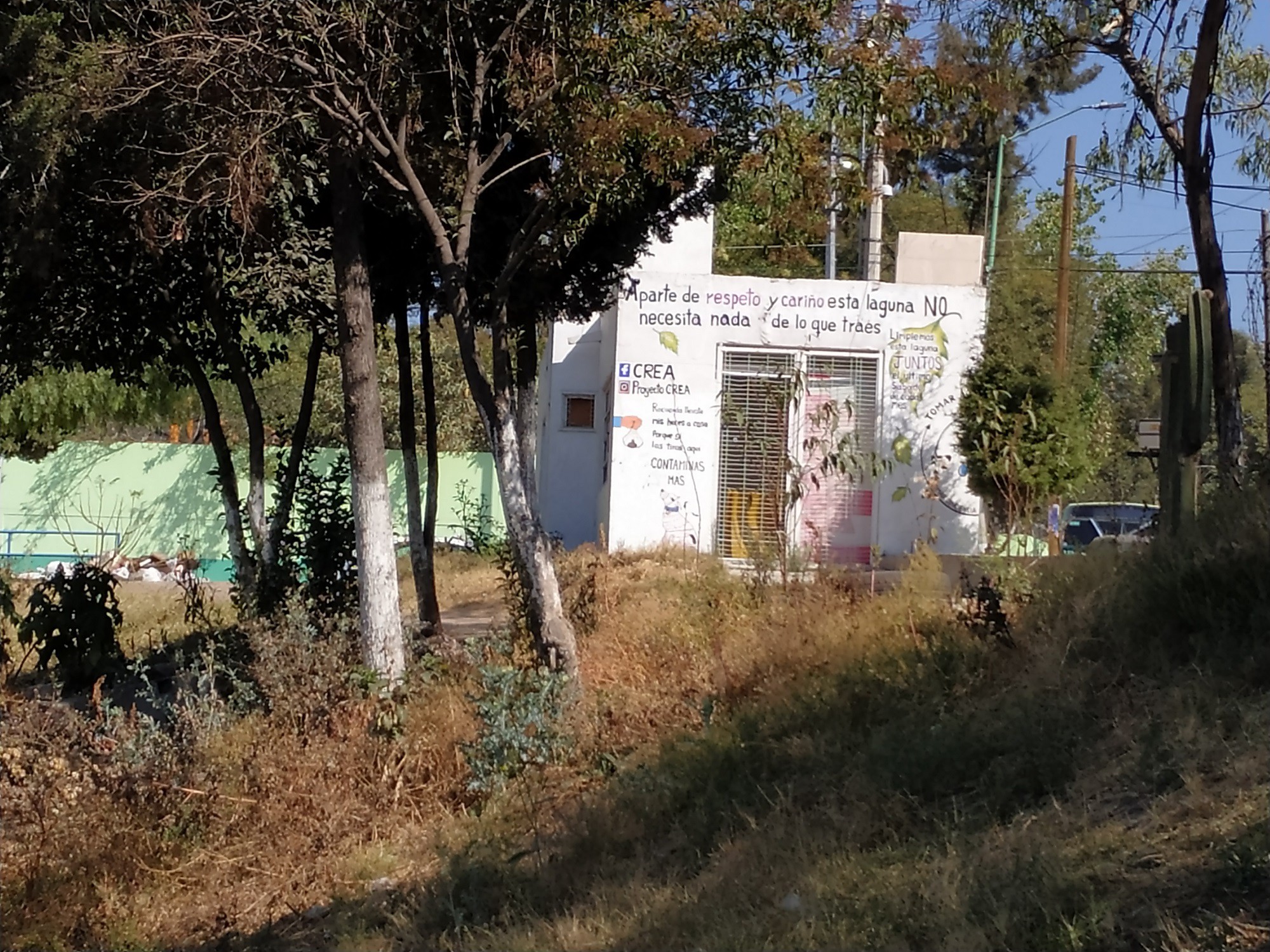
- One important thing is to find a safe area where to monitor our system with the receiver module. To achieve it, I went through the ecological area of my community and found a perfect room module for this task, as shown in the image below. I just have to ask the local authority for permission to do so.
![]()
As soon as I can I will publish the new version of my project. Thank you for taking time to read my project.
-
12. Testing LoRaWAN and IoT Connection
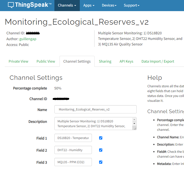
07/26/2022 at 21:19 • 0 commentsCHANNEL CONFIGURATION IN THE THINGSPEAK PLATFORM
Below you can see the new channel created on the ThingSpeak platform.
![]()
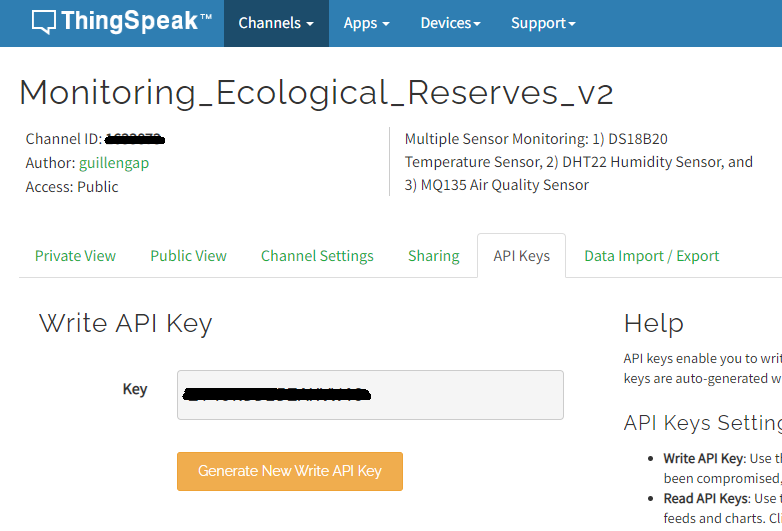
Don't forget to take note of the Write API key.
![]()
TESTING LORAWAN AND IOT CONNECTION
In the video below I show you two tests carried out: a) in the first, the transmitter and the receiver are inside a room in order to verify that everything is working well; b) in the second, the transmitter is placed in the ecological reserve.
IMAGE GALLERY
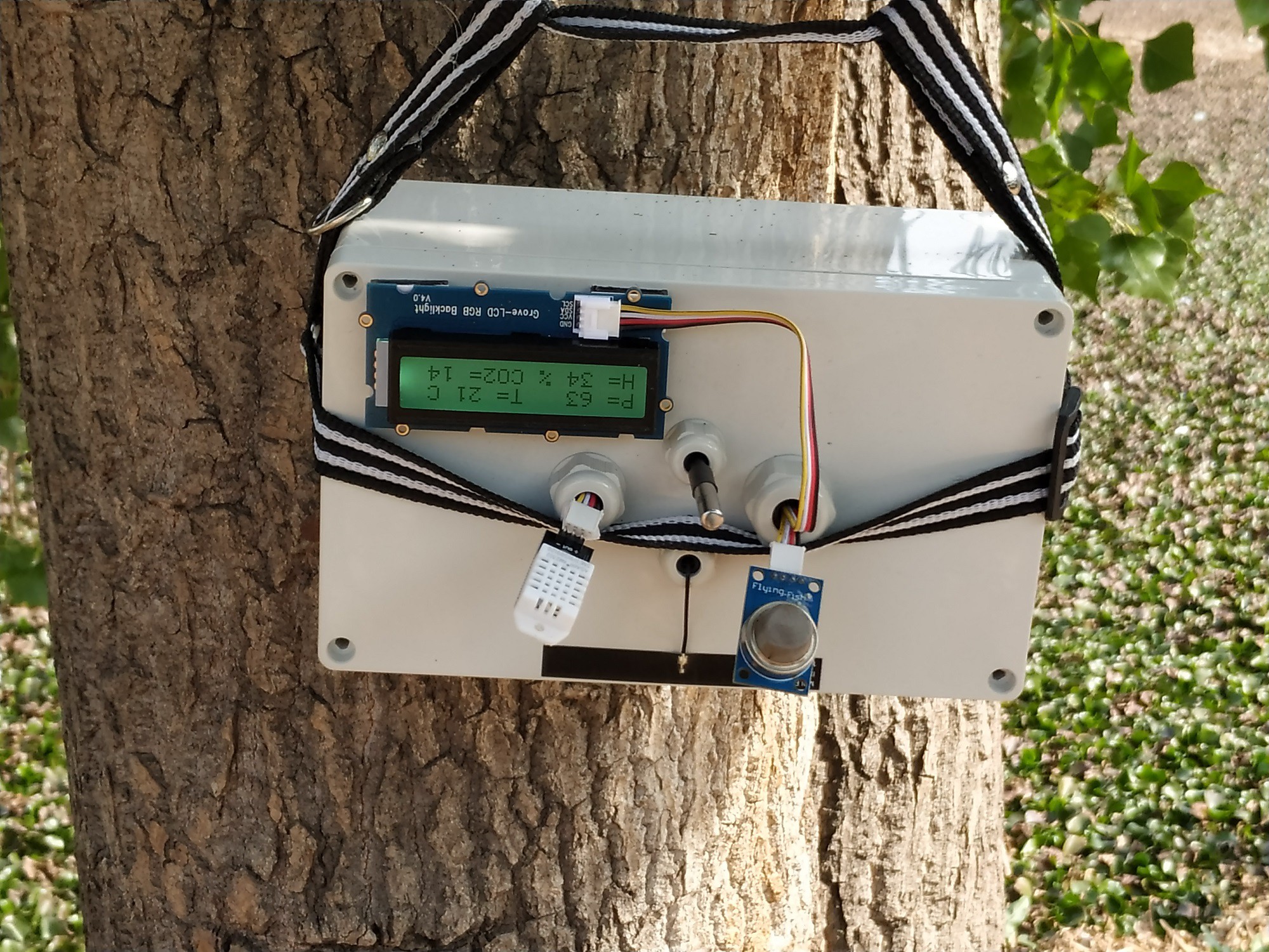
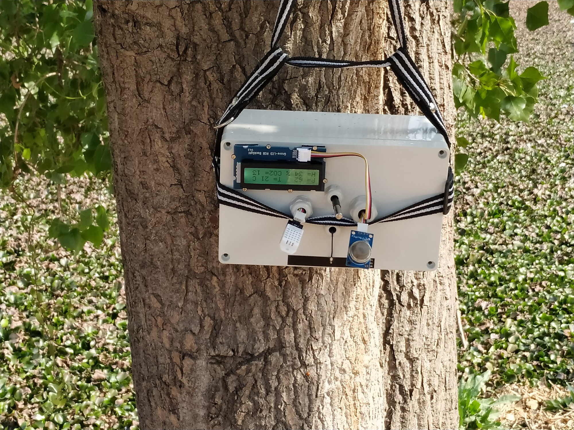
On this occasion, I decided to solve the problem of having better signal reception. For this reason, I made a case with straps to attach the transmitting device to test on various trees and improve line of sight.
![]()
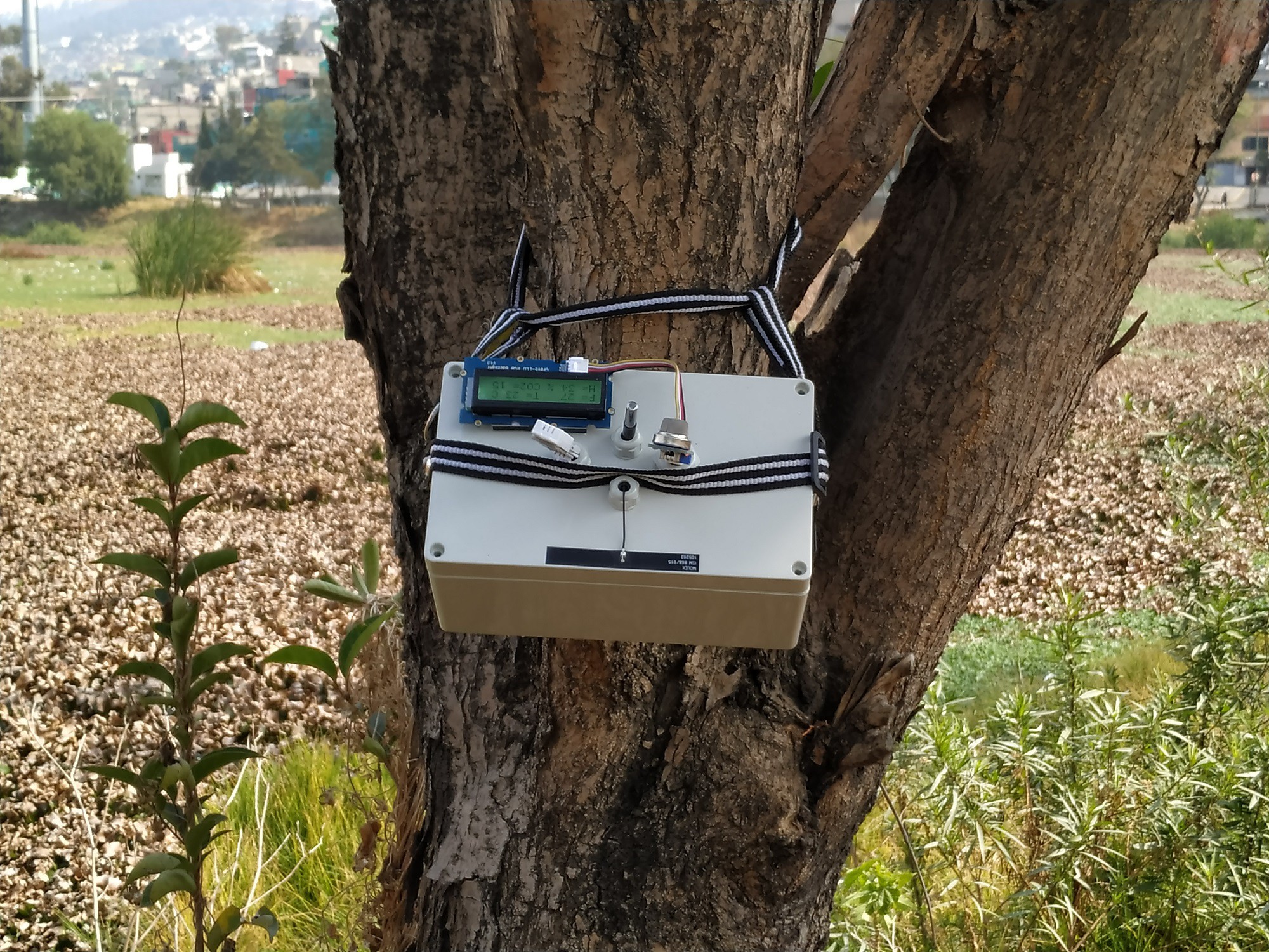
This is the second tree in my attempt to improve signal quality.
![]()
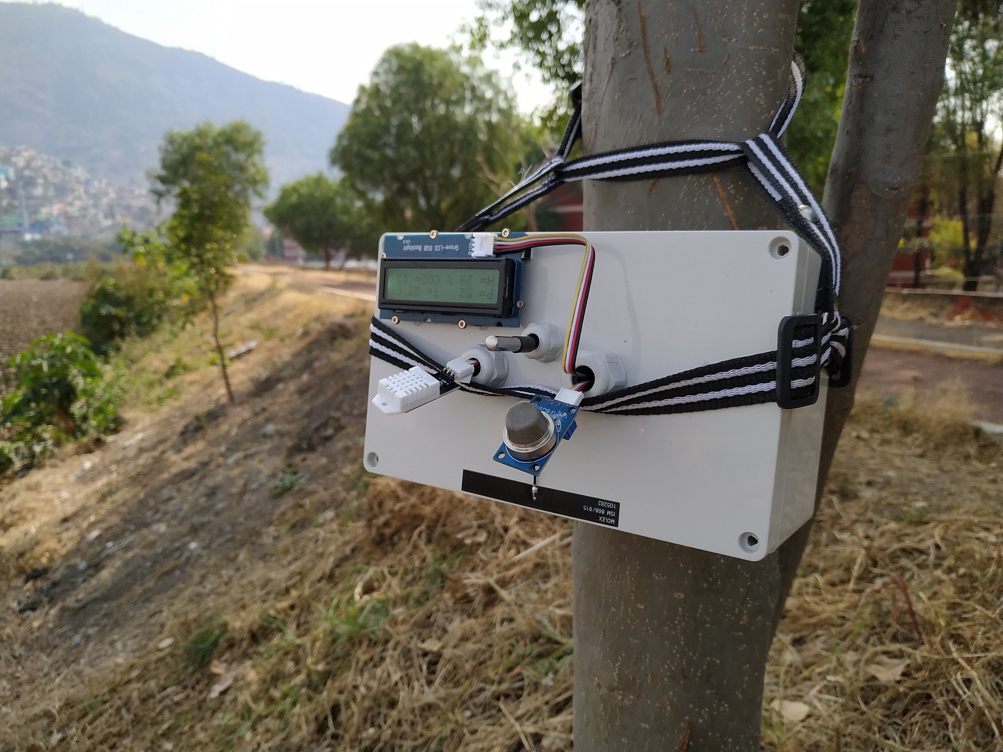
And finally my third attempt to improve the quality of the signal.
![]()
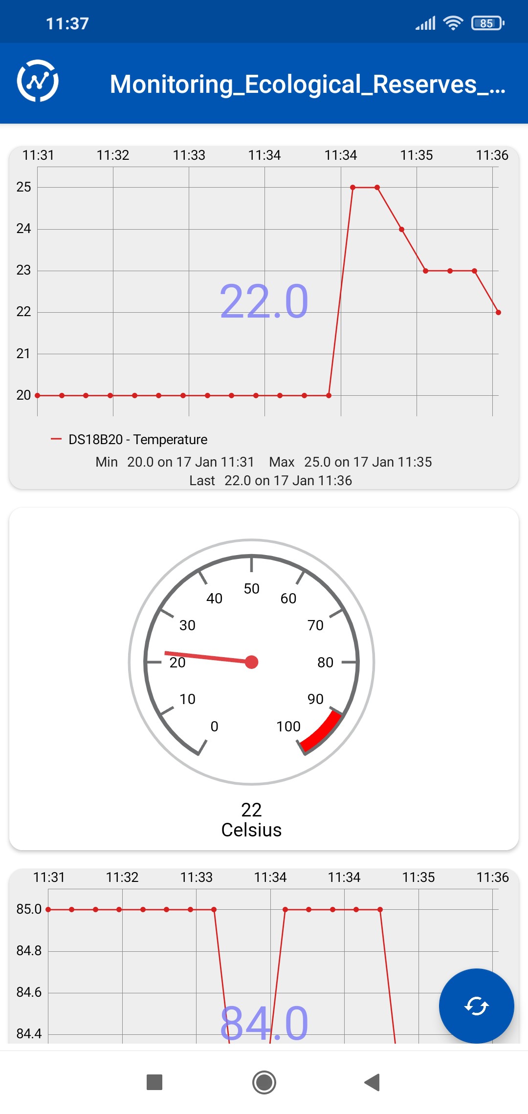
What I can guarantee is that I am ecstatic with the beauty of nature.. Below is a screenshot with the ThingView app.
![]()
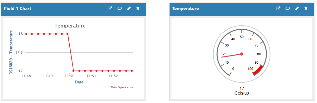
Here is an example of temperature capture with the ThingSpeak platform
![]()
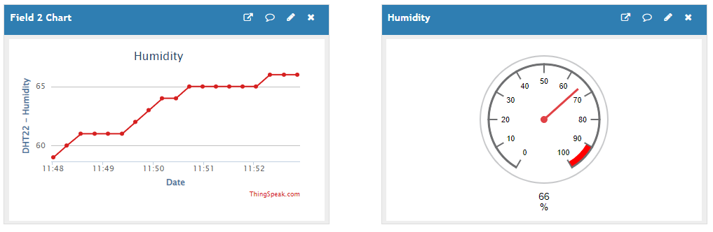
Now a screenshot of the relative humidity.
![]()
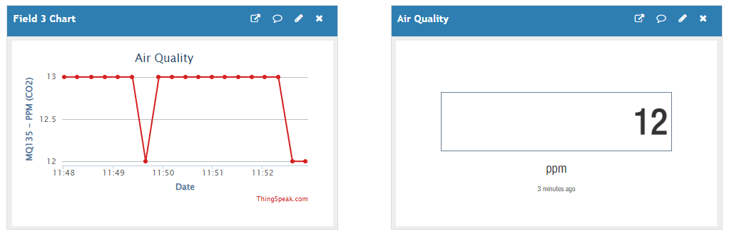
And finally a capture of carbon dioxide pollution.
![]()
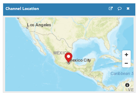
This area has low levels of contamination at the moment. You should know that ThingSpeak can also give you the area map as long as you give it the GPS coordinates.
![]()
-
11. LoRaWAN and IoT Connection
07/26/2022 at 21:16 • 0 comments![]()
LORAWAN TRANSMITTER
Below I show you the schematic diagram of the transmitter with multiple sensors.
![]()
Below I show you the code used to upload it to the Arduino MKR WAN 1300 transmitter board.
LoRaSender_v5.ino
// AUTHOR: GUILLERMO PEREZ GUILLEN

#include <SPI.h> // LoRa->
#include <LoRa.h>
#include <OneWire.h> // DS18B20->
#include <DallasTemperature.h>
#include <Wire.h> // LCD->
#include "rgb_lcd.h"
rgb_lcd lcd;
const int colorR = 173;
const int colorG = 255;
const int colorB = 47;

#include "DHT.h" // DHT22 ->
#define DHTPIN 3    // Pin where the sensor is connected
#define DHTTYPE DHT22   // DHT22 sensor
DHT dht(DHTPIN, DHTTYPE);

// DS18B20-> Data wire is plugged into port 2 on the Arduino
#define ONE_WIRE_BUS 2
OneWire oneWire(ONE_WIRE_BUS);
DallasTemperature sensors(&oneWire);

#define anInput     A0 // MQ135-> analog feed from MQ135
int counter = 0;

void setup() {
  // set up the LCD's number of columns and rows:
  lcd.begin(16, 2);
  lcd.setRGB(colorR, colorG, colorB);
  lcd.print("ECOLOGY!");
  pinMode(anInput,INPUT); // MQ135
  lcd.setCursor(0, 1); // LCD
  lcd.print("LoRa Sender");
  if (!LoRa.begin(915E6)) {
  lcd.setCursor(0, 1); // LCD
  lcd.print("Starting LoRa failed!");
    while (1);
  }
  sensors.begin();   //temperature sensor starts
  dht.begin();
}

void loop() {
  int co2now[10]; //int array for co2 readings
  int co2raw = 0; //int for raw value of co2
  int co2ppm = 0; //int for calculated ppm
  int zzz = 0; //int for averaging
  for (int x = 0;x<10;x++) // MQ135-> samplpe co2 10x over 2 seconds
  {
    co2now[x]=analogRead(A0);
    delay(200);
  }
  for (int x = 0;x<10;x++) // add samples together
  {
    zzz=zzz + co2now[x];
  }
  co2raw = zzz/10; // divide samples by 10
  co2ppm = co2raw;
  int h = dht.readHumidity(); //We read the Humidity
  sensors.requestTemperatures();   //The command to read the temperature is sent
  int temp = sensors.getTempCByIndex(0); //The temperature is obtained in ยบC
  // send packet
  LoRa.beginPacket();
  LoRa.print(temp);
  LoRa.print(",");
  LoRa.print(h);
  LoRa.print(",");
  LoRa.print(co2ppm);
  LoRa.endPacket();
  lcd.clear();
  lcd.setCursor(0, 0); // LCD
  lcd.print("P=");
  lcd.setCursor(3, 0); // LCD
  lcd.print(counter);
  lcd.setCursor(8, 0); // LCD
  lcd.print("T=");
  lcd.setCursor(11, 0); // LCD
  lcd.print(temp);
  lcd.setCursor(14, 0); // LCD
  lcd.print("C");
  lcd.setCursor(0, 1); // LCD
  lcd.print("H=");
  lcd.setCursor(3, 1); // LCD
  lcd.print(h);
  lcd.setCursor(6, 1); // LCD
  lcd.print("%");
  lcd.setCursor(8, 1); // LCD
  lcd.print("CO2=");
  lcd.setCursor(13, 1); // LCD
  lcd.print(co2ppm);
  counter++;
  delay(13000);
}
LORAWAN RECEIVER
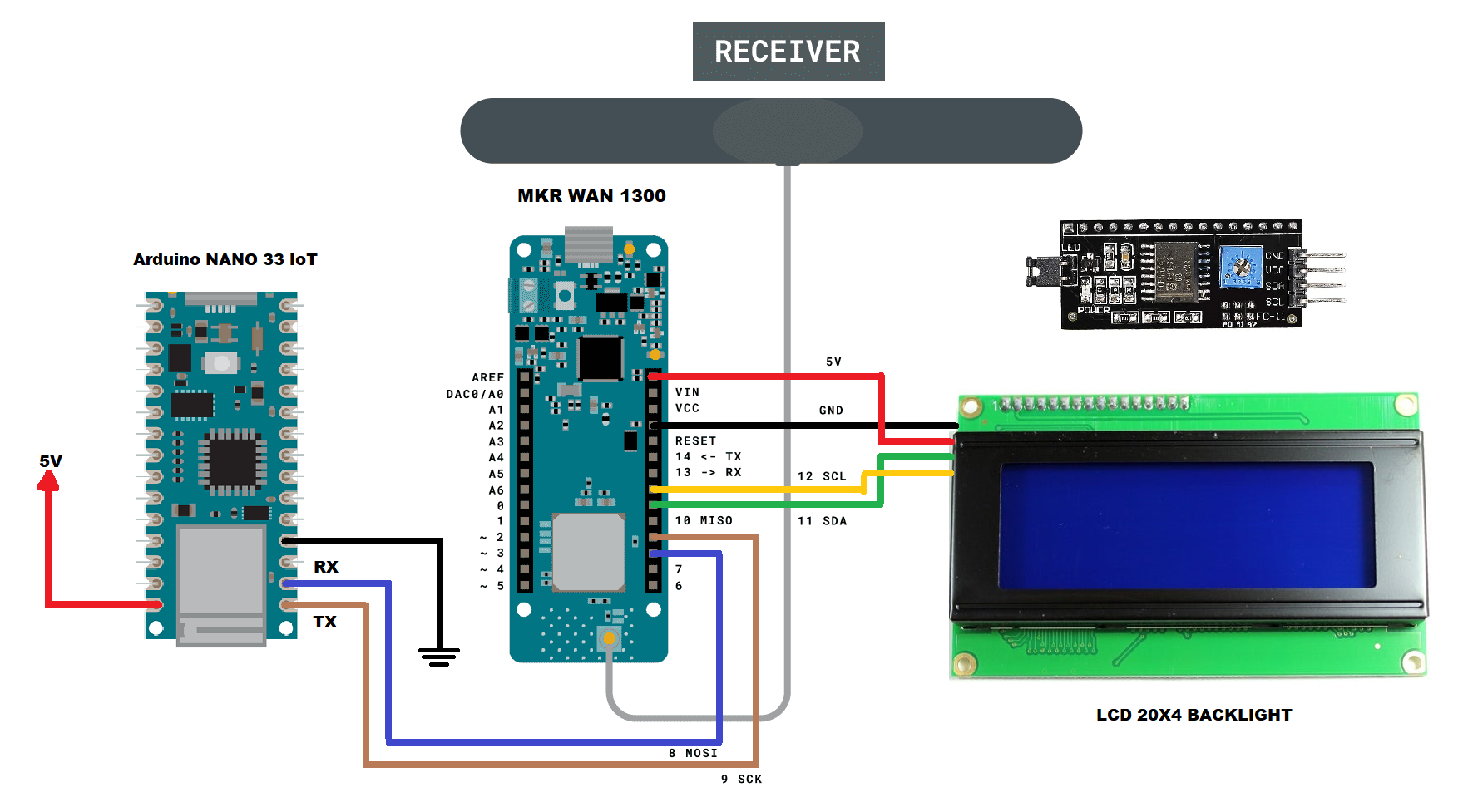
Below I show you the schematic diagram of the receiver. device
![]()
Below I show you the code used to upload it to the Arduino MKR WAN 1300 receiver board.
LoRaReceiver_v5.ino
// AUTHOR: GUILLERMO PEREZ GUILLEN

#include <SPI.h>
#include <LoRa.h>
#include <Arduino.h>   // SERCOM1
#include "wiring_private.h" // SERCOM1

// SERCOM1: Rx->D9 & Tx->D8
Uart Serial3 (&sercom1, 9, 8, SERCOM_RX_PAD_1, UART_TX_PAD_0);
void SERCOM1_Handler()
{
  Serial3.IrqHandler();
}

#include <Wire.h> // Library for I2C communication
#include <LiquidCrystal_I2C.h> // Library for LCD
LiquidCrystal_I2C lcd = LiquidCrystal_I2C(0x27, 20, 4); // Change to (0x27,16,2) for 16x2 LCD.

char cadena[30]; //We create an array that will store the characters that we will write in the PC console. We assign a limit of characters, in this case 30
byte posicion=0;  //Variable to change the position of the characters in the array
int valor;  //Integer Variable

void setup() {
  lcd.init();  // Initiate the LCD:
  lcd.backlight();
  pinMode(LED_BUILTIN, OUTPUT);
  Serial.begin(9600);
  Serial3.begin(9600); // SERCOM1
  // Assign pins 8 & 9 SERCOM1 functionality
  pinPeripheral(8, PIO_SERCOM);
  pinPeripheral(9, PIO_SERCOM);
  Serial.println("LoRa Receiver")
  if (!LoRa.begin(915E6)) {
    Serial.println("Starting LoRa failed!");
    while (1);
  }
}

void loop() {
  int packetSize = LoRa.parsePacket();
  if (packetSize) {
    memset(cadena, 0,sizeof(cadena));//memset deletes the contents of the array "cadena" from position 0 to the end sizeof
    // received a packet
    Serial.print("Received packet... ");
    // read packet
    while (LoRa.available()) {
      char dedos= (char)LoRa.read();
      Serial.print(dedos);
      Serial3.print(dedos);
      cadena[posicion]=dedos;//Read a character from the string "cadena" from "posicion", then read the next character with "posicion++"
      posicion++;
    }
    posicion=0;
    int signal_rx = LoRa.packetRssi();
    // print RSSI of packet
    Serial.print(" with RSSI ");
    Serial.println(signal_rx);
    int parte1 = getValue(cadena,',',0).toInt();
    int parte2 = getValue(cadena,',',1).toInt();
    int parte3 = getValue(cadena,',',2).toInt();
    Serial.println(parte1);
    delay(100);
    Serial.println(parte2);
    delay(100);
    Serial.println(parte3);
    delay(100);
    lcd.clear();
    lcd.setCursor(0, 0);
    lcd.print("RSSI =");
    lcd.setCursor(7, 0);
    lcd.print(signal_rx);
    lcd.setCursor(11, 0);
    lcd.print("dBm");
    lcd.setCursor(0, 1);
    lcd.print("Temp =");
    lcd.setCursor(8, 1);
    lcd.print(parte1);
    lcd.setCursor(11, 1);
    lcd.print("C");
    lcd.setCursor(0, 2);
    lcd.print("Hum =");
    lcd.setCursor(8, 2);
    lcd.print(parte2);
    lcd.setCursor(11, 2);
    lcd.print("%");
    lcd.setCursor(0, 3);
    lcd.print("CO2 =");
    lcd.setCursor(8, 3);
    lcd.print(parte3);
    lcd.setCursor(11, 3);
    lcd.print("PPM");
    digitalWrite(LED_BUILTIN, HIGH);
    delay(2000);
    digitalWrite(LED_BUILTIN, LOW);
    delay(12000);
  }
}

String getValue(String data, char separator, int index)
{
  int found = 0;
  int strIndex[] = {0, -1};
  int maxIndex = data.length()-1;
  for(int i=0; i<=maxIndex && found<=index; i++){
    if(data.charAt(i)==separator || i==maxIndex){
        found++;
        strIndex[0] = strIndex[1]+1;
        strIndex[1] = (i == maxIndex) ? i+1 : i;
    }
  }
  return found>index ? data.substring(strIndex[0], strIndex[1]) : "";
}
IOT CONNECTION TO THE THINGSPEAK PLATFORM
Finally, below I show you the code to program the Arduino NANO 33 IoT board. this code processes the three sensors information and sends it to the ThingSpeak IoT platform.
Nano33Iot_Multiple_Sensors.ino
// AUTHOR: GUILLERMO PEREZ GUILLEN

#include <WiFiNINA.h> // THINGSPEAK->
#include "secrets.h"
#include "ThingSpeak.h"

char ssid[] = SECRET_SSID;    //  your network SSID (name)
char pass[] = SECRET_PASS;   // your network password
int keyIndex = 0;            // your network key Index number (needed only for WEP)
WiFiClient  client;
unsigned long myChannelNumber = SECRET_CH_ID;
const char * myWriteAPIKey = SECRET_WRITE_APIKEY;

char cadena[30]; //We create an array that will store the characters that we will write in the PC console. We assign a limit of characters, in this case 30
byte posicion=0;  //Variable to change the position of the characters in the array
int valor;  //Integer Variable

void setup()
{
  Serial.begin(9600);
  Serial1.begin(9600);
  // THINGSPEAK-> check for the WiFi module:
  if (WiFi.status() == WL_NO_MODULE) {
    Serial.println("Communication with WiFi module failed!");
    // don't continue
    while (true);
  }
  String fv = WiFi.firmwareVersion();
  if (fv != "1.0.0") {
    Serial.println("Please upgrade the firmware");
  }
  ThingSpeak.begin(client);  //Initialize ThingSpeak
}

void loop()
{
  // THINGSPEAK-> Connect or reconnect to WiFi
  if(WiFi.status() != WL_CONNECTED){
    Serial.print("Attempting to connect to SSID: ");
    Serial.println(SECRET_SSID);
    while(WiFi.status() != WL_CONNECTED){
      WiFi.begin(ssid, pass); // Connect to WPA/WPA2 network. Change this line if using open or WEP network
      Serial.print(".");
      delay(5000);
    }
    Serial.println("\nConnected.");
  }
  if(Serial1.available()) //Is there data inside the buffer?
  {
    memset(cadena, 0,sizeof(cadena));//memset deletes the contents of the array "cadena" from position 0 to the end sizeof

    while(Serial1.available()>0) //As long as there is data in the buffer execute the function
    {
      delay(5);
      cadena[posicion]=Serial1.read();//Read a character from the string "cadena" from "posicion", then read the next character with "posicion++"
      posicion++;
    }
    posicion=0;
    // Write to ThingSpeak. There are up to 8 fields in a channel, allowing you to store up to 8 different
    // pieces of information in a channel.  Here, we write to field 1.
    int parte1 = getValue(cadena,',',0).toInt();
    int parte2 = getValue(cadena,',',1).toInt();
    int parte3 = getValue(cadena,',',2).toInt();
    Serial.println(parte1);
    delay(100);
    Serial.println(parte2);
    delay(100);
    Serial.println(parte3);
    delay(100);
    // set the fields with the values
    ThingSpeak.setField(1, parte1);
    ThingSpeak.setField(2, parte2);
    ThingSpeak.setField(3, parte3);
  // write to the ThingSpeak channel
  int x = ThingSpeak.writeFields(myChannelNumber, myWriteAPIKey);
  if(x == 200){
    Serial.println("Channel update successful.");
  }
  else{
    Serial.println("Problem updating channel. HTTP error code " + String(x));
  }
    delay(15000);
  }
}

String getValue(String data, char separator, int index)
{
  int found = 0;
  int strIndex[] = {0, -1};
  int maxIndex = data.length()-1;
  for(int i=0; i<=maxIndex && found<=index; i++){
    if(data.charAt(i)==separator || i==maxIndex){
        found++;
        strIndex[0] = strIndex[1]+1;
        strIndex[1] = (i == maxIndex) ? i+1 : i;
    }
  }
  return found>index ? data.substring(strIndex[0], strIndex[1]) : "";
}
Don't forget to type the corresponding credentials to connect to the IoT provider. In the download section you can get the "secrets.h" file.
// and connection details #define SECRET_SSID "*********" // replace MySSID with your WiFi network name #define SECRET_PASS "************" // replace MyPassword with your WiFi password #define SECRET_CH_ID ******* // replace ******* with your channel number #define SECRET_WRITE_APIKEY "****************" // replace **************** with your channel write API Key -
10. How to Connect LoRaWAN to an IoT Provider through the Arduino NANO 33 IoT
07/26/2022 at 20:53 • 0 commentsIn this part of my project, the challenge is to connect my LoRa network to an IoT provider, but one with cost-effective. Below is the schematic diagram.
![]()
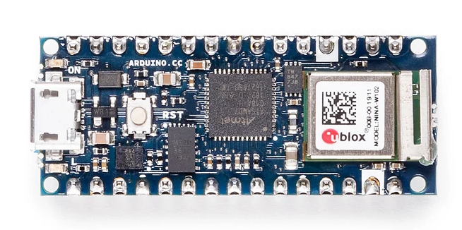
In this project I am going to connect my LoRa network with an IoT provider through the Arduino NANO 33 IoT board. Reason:
Its an economic solution, since the Arduino NANO 33 IoT board has an average cost of $20.70 USD.
![]()
On the other hand, the Gateway Lora RAK2245 board has a price of: $ 154.55 USD.
![]()
Creating a New Serial Port to the Arduino MKR WAN 1300 Board
When I checked out the ATSAMD21 chip (the processor used in the Arduino MKR WAN 1300 board), I was very happy to see that the chip has 6 "SERCOM"s, a.k.a SERial COMmunication modules. Each one of these modules can be used for I2C, SPI or Serial. That means you can have 3 UART's & 3 SPI's, or maybe 2 SPI's and 4 I2C's. Basically, you have a ton of options for adding more hardware support for the most common 3 chip-to-chip protocols.
UART has only 2 pins, RX & TX. UARTs are a real pain to emulate or bitbang due to their very precise timing and their asynchronous RX lines are very difficult to do if you dont have hardware interrupt pins available. For that reason, being able to create new Serial's is awesome.
Now, what I need is to create a new serial port on the Arduino MKR WAN 1300 board to connect it with the Arduino NANO 33 IoT board via serial port. In this way the Arduino NANO board will receive the data from the sensors and can send them to any IoT provider.
How Serial is Created Now
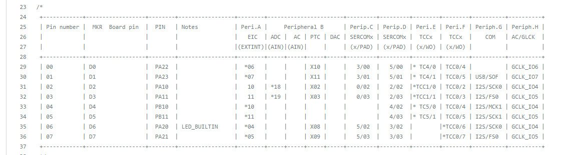
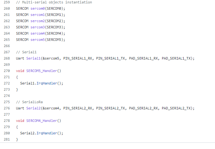
You can find the actual code that is used to create the "Serial" SERCOM in variant.cpp
![]()
You will see the serial objects on:
![]()
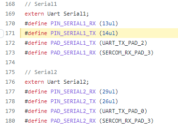
The actual definitions of those macros is available in variant.h
![]()
OK so let's make a new Serial SERCOM already
I want to make a Serial! Lets try creating a new SERCOM and testing it out. Let's make a Serial device on SERCOM #1, lets look at what pin muxing options we've got:
PIN number PIN arduino SERCOM PA16 D8 (MOSI) SERCOM1.0 PA17 D9 (SCK) SERCOM1.1 PA19 D10 (MISO) SERCOM1.3 PA18 D24 (USB) SERCOM1.2 Rules:
- Tx only works on PAD 0 and PAD 2
- RX works in any PAD
I have selected next pins:
- D8 FOR TX
- D9 FOR RX
In the next chapter I will show you how to program this data into the Arduino MKR WAN 1300 receiver board.
-
9. LoRaWAN´s Test with Multiple Sensors
07/26/2022 at 20:41 • 0 commentsLORAWAN´S SIMPLE TEST
Before doing the field test, I decided to do a basic test indoor in order to correct any hardware or software issues. In the figure below I show you the devices assembled and ready for the basic test.
![]()
In the video below I show you the test inside my house and the three sensors work without problems and the receiver device receives the data.
LORAWAN´S FIELD TEST
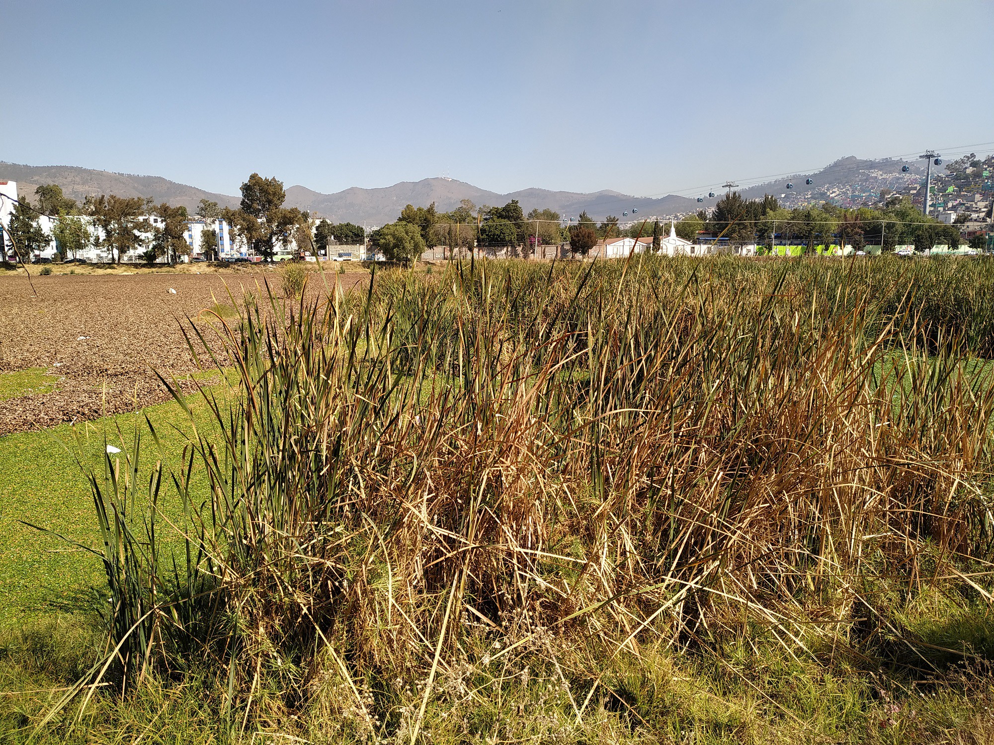
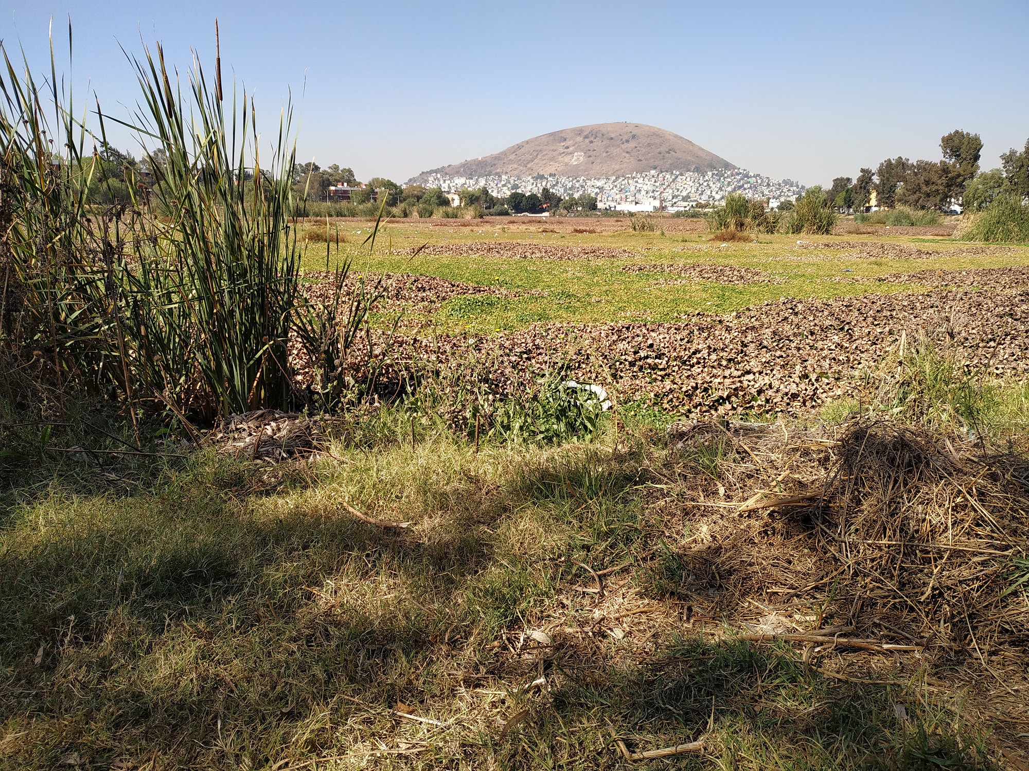
This is the place I chose to test my LoRa devices.
![]()
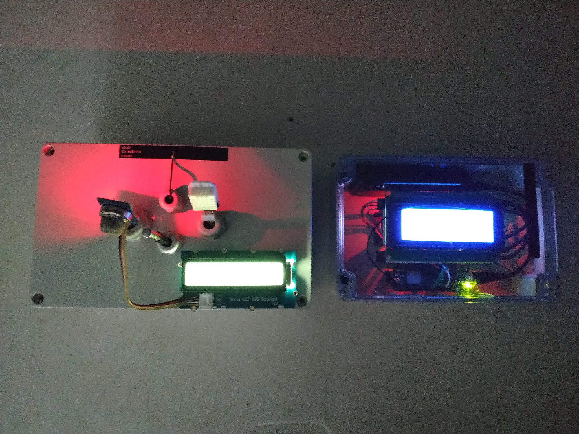
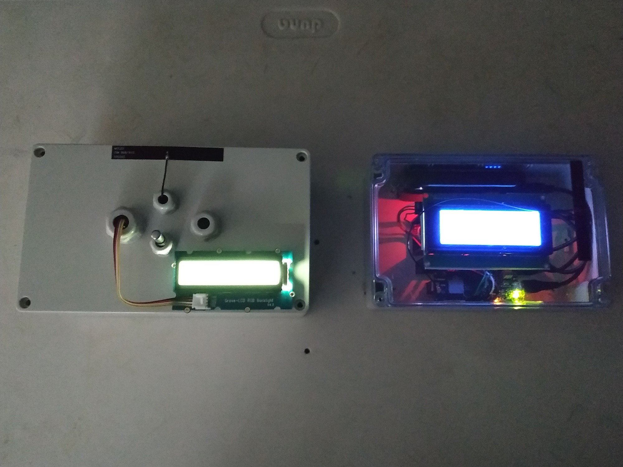
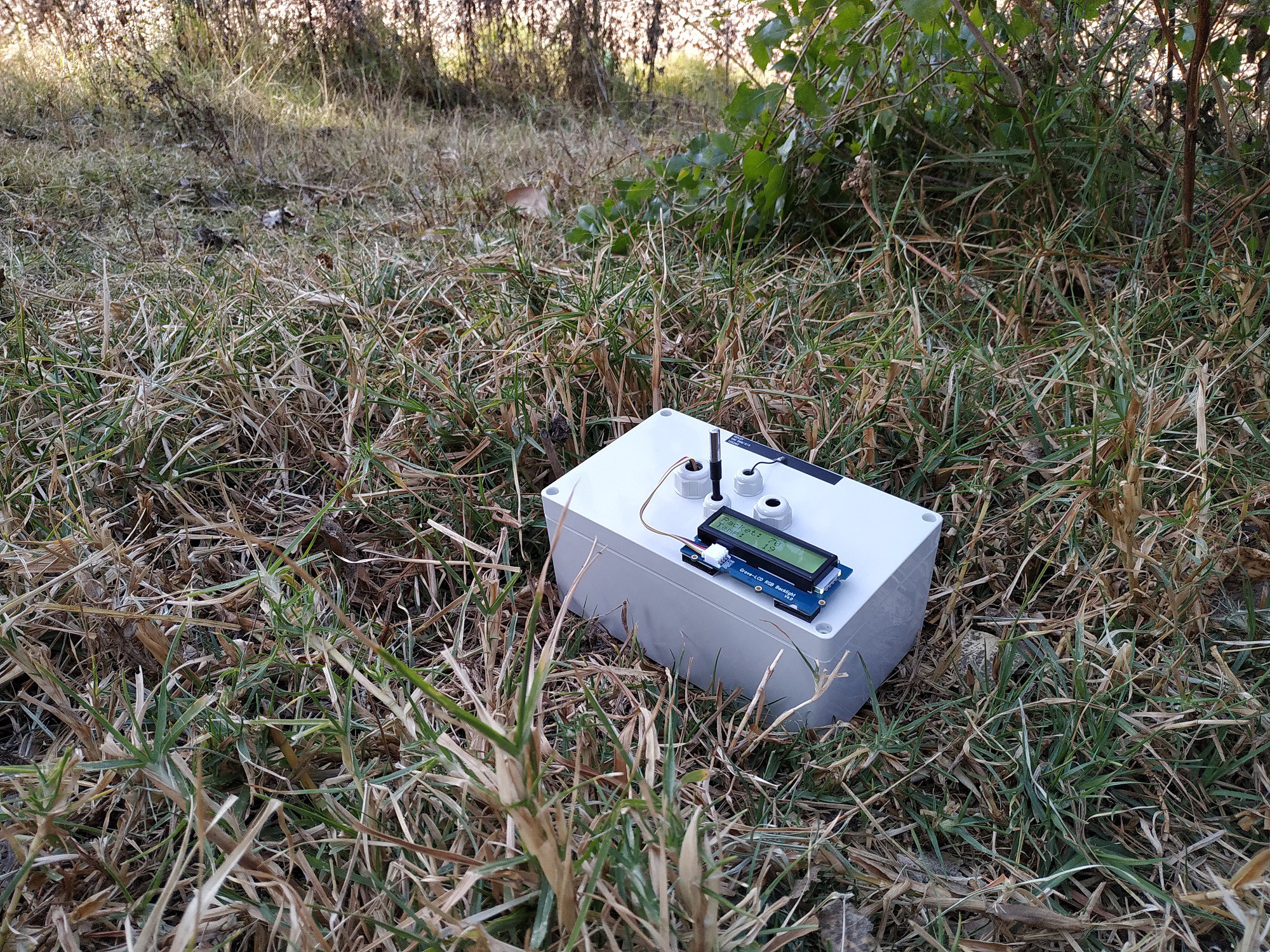
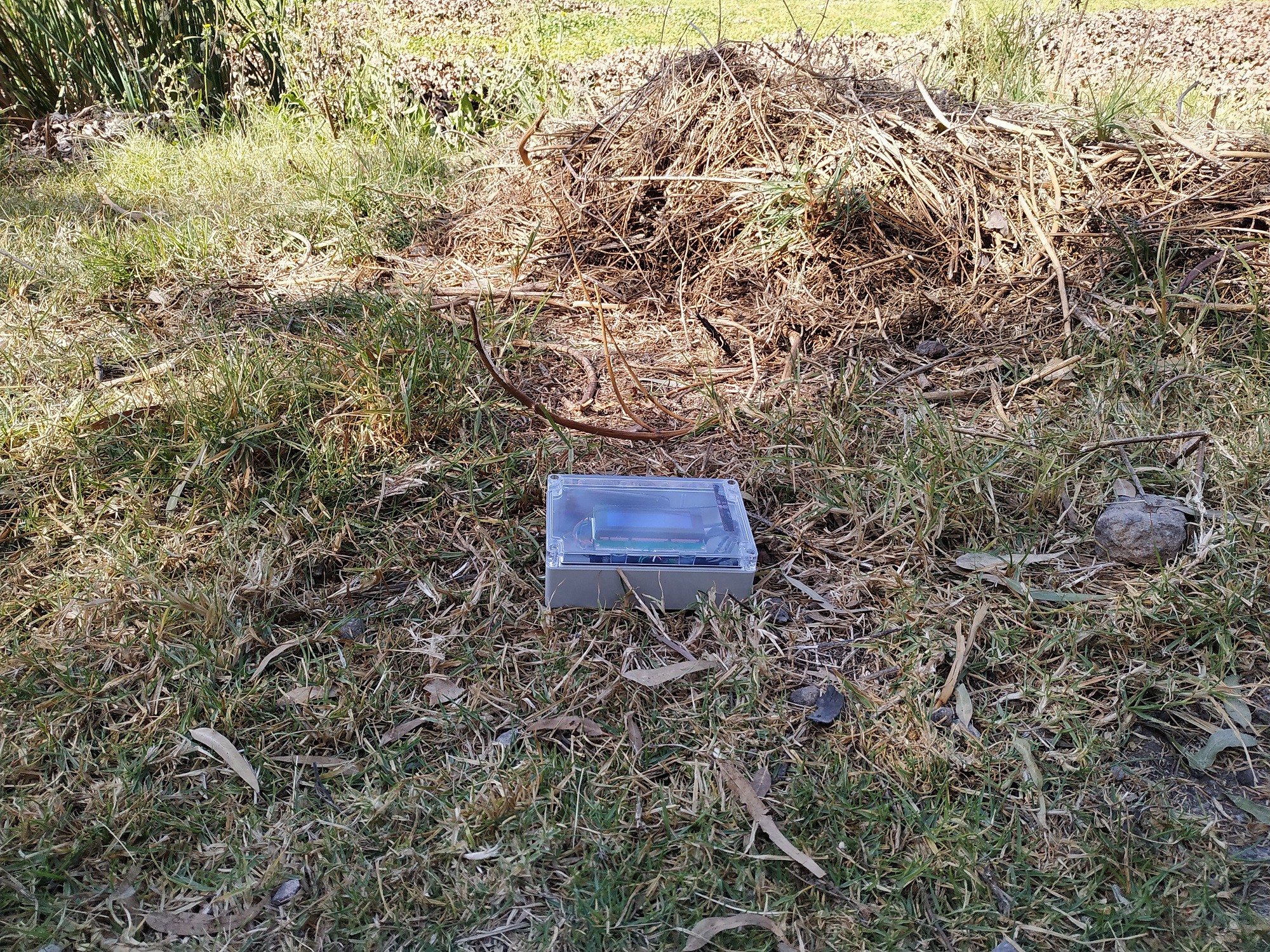
In the image below I show you the transmitter and the receiver ready to work.
![]()
Finally, in the video below I show you the tests carried out with this system.
Notes:
- Today there was some wind so the air is very clean, some cold fronts are even arriving from the north, so the weather is getting colder and rains are beginning to fall.
- The tests were carried out successfully. In the following chapters I will show you how to link the data to an IoT service provider cheaply, and without spending a lot of money on hardware.
-
8. Modifying Receiver Code for Multiple Sensors
07/26/2022 at 20:19 • 0 commentsRECEIVER SCHEMATIC DIAGRAM
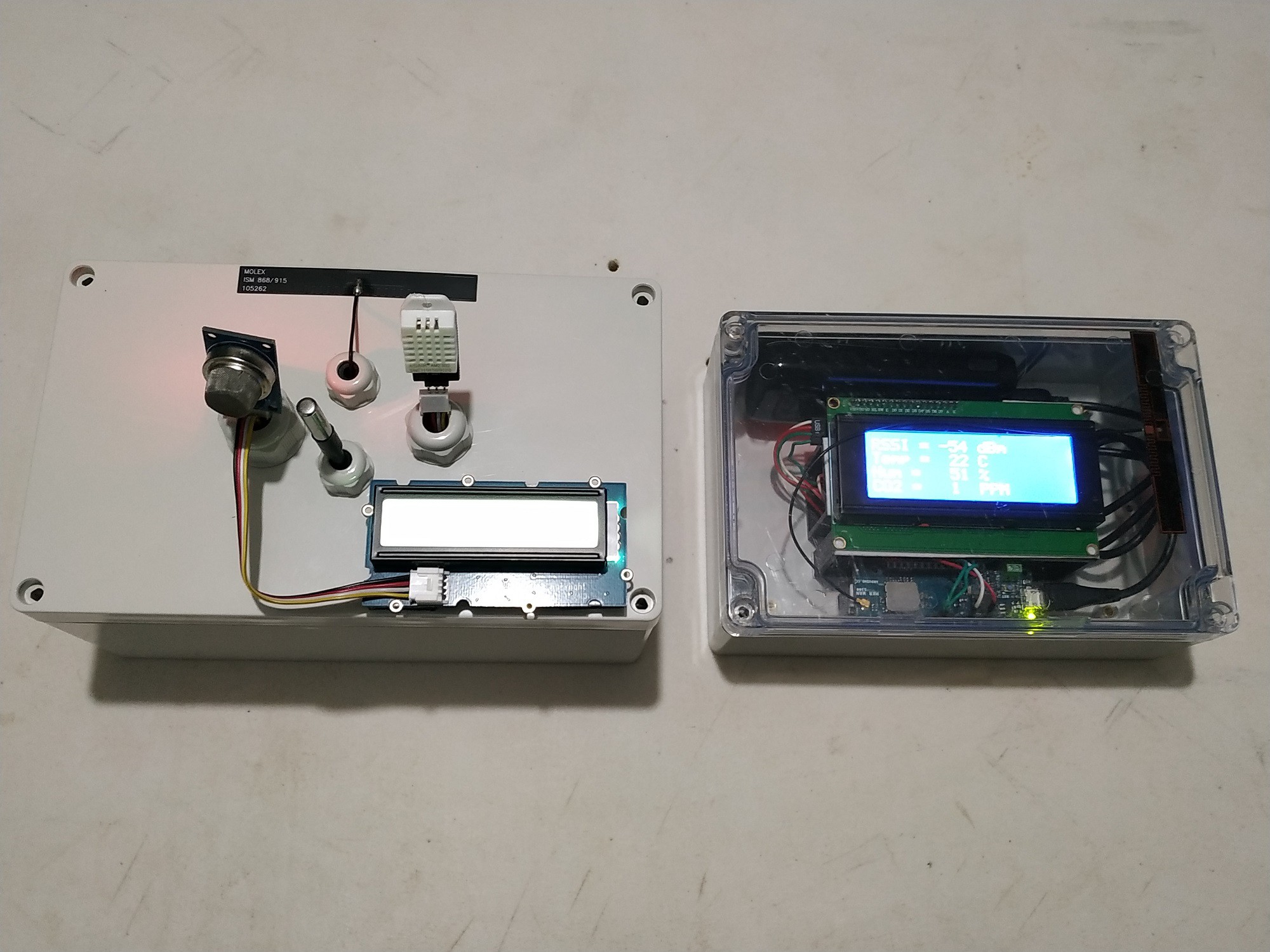
In the figure below I show you the electrical diagram of the receiver device
![]()
As you can see, there are no hardware changes, however the code must have changes since we will receive data from three sensors and these must be separated and shown on the display. All this through code. In the figure below I show you the transmitter and the receiver.
![]()
RECEIVER CODE
There were no hardware changes on the receiving device. However, in the software there were changes, and these are shown in the code below:
LoRaReceiver_v3.ino
// AUTHOR: GUILLERMO PEREZ GUILLEN #include <SPI.h> #include <LoRa.h> #include <Wire.h> // Library for I2C communication #include <LiquidCrystal_I2C.h> // Library for LCD LiquidCrystal_I2C lcd = LiquidCrystal_I2C(0x27, 20, 4); // Change to (0x27,16,2) for 16x2 LCD. char cadena[30]; //We create an array that will store the characters that we will write in the PC console. We assign a limit of characters, in this case 30 byte posicion=0; //Variable to change the position of the characters in the array int valor; //Integer Variable void setup() { lcd.init(); // Initiate the LCD: lcd.backlight(); pinMode(LED_BUILTIN, OUTPUT); Serial.begin(9600); Serial.println("LoRa Receiver"); if (!LoRa.begin(915E6)) { Serial.println("Starting LoRa failed!"); while (1); } } void loop() { // try to parse packet int packetSize = LoRa.parsePacket(); if (packetSize) { memset(cadena, 0,sizeof(cadena));//memset deletes the contents of the array "cadena" from position 0 to the end sizeof // received a packet Serial.print("Received packet... "); // read packet while (LoRa.available()) { char dedos= (char)LoRa.read(); Serial.print(dedos); cadena[posicion]=dedos;//Read a character from the string "cadena" from "posicion", then read the next character with "posicion++" posicion++; } posicion=0; int signal_rx = LoRa.packetRssi(); // print RSSI of packet Serial.print(" with RSSI "); Serial.println(signal_rx); int parte1 = getValue(cadena,',',0).toInt(); int parte2 = getValue(cadena,',',1).toInt(); int parte3 = getValue(cadena,',',2).toInt(); Serial.println(parte1); delay(100); Serial.println(parte2); delay(100); Serial.println(parte3); delay(100); // LCD data lcd.clear(); lcd.setCursor(0, 0); lcd.print("RSSI ="); lcd.setCursor(7, 0); lcd.print(signal_rx); lcd.setCursor(11, 0); lcd.print("dBm"); lcd.setCursor(0, 1); lcd.print("Temp ="); lcd.setCursor(8, 1); lcd.print(parte1); lcd.setCursor(11, 1); lcd.print("C"); lcd.setCursor(0, 2); lcd.print("Hum ="); lcd.setCursor(8, 2); lcd.print(parte2); lcd.setCursor(11, 2); lcd.print("%"); lcd.setCursor(0, 3); lcd.print("CO2 ="); lcd.setCursor(8, 3); lcd.print(parte3); lcd.setCursor(11, 3); lcd.print("PPM"); digitalWrite(LED_BUILTIN, HIGH); delay(2000); digitalWrite(LED_BUILTIN, LOW); } } String getValue(String data, char separator, int index) { int found = 0; int strIndex[] = {0, -1}; int maxIndex = data.length()-1; for(int i=0; i<=maxIndex && found<=index; i++){ if(data.charAt(i)==separator || i==maxIndex){ found++; strIndex[0] = strIndex[1]+1; strIndex[1] = (i == maxIndex) ? i+1 : i; } } return found>index ? data.substring(strIndex[0], strIndex[1]) : ""; }- First you have to receive the data in a character string.
- How did I separate the data from the three sensors? There are several methods to do it, I did it using the comma (,).
In the next post we will see a demonstration of how this project works.
-
7. Adding Multiple Sensors: DS18B20, DHT22 and MQ-135
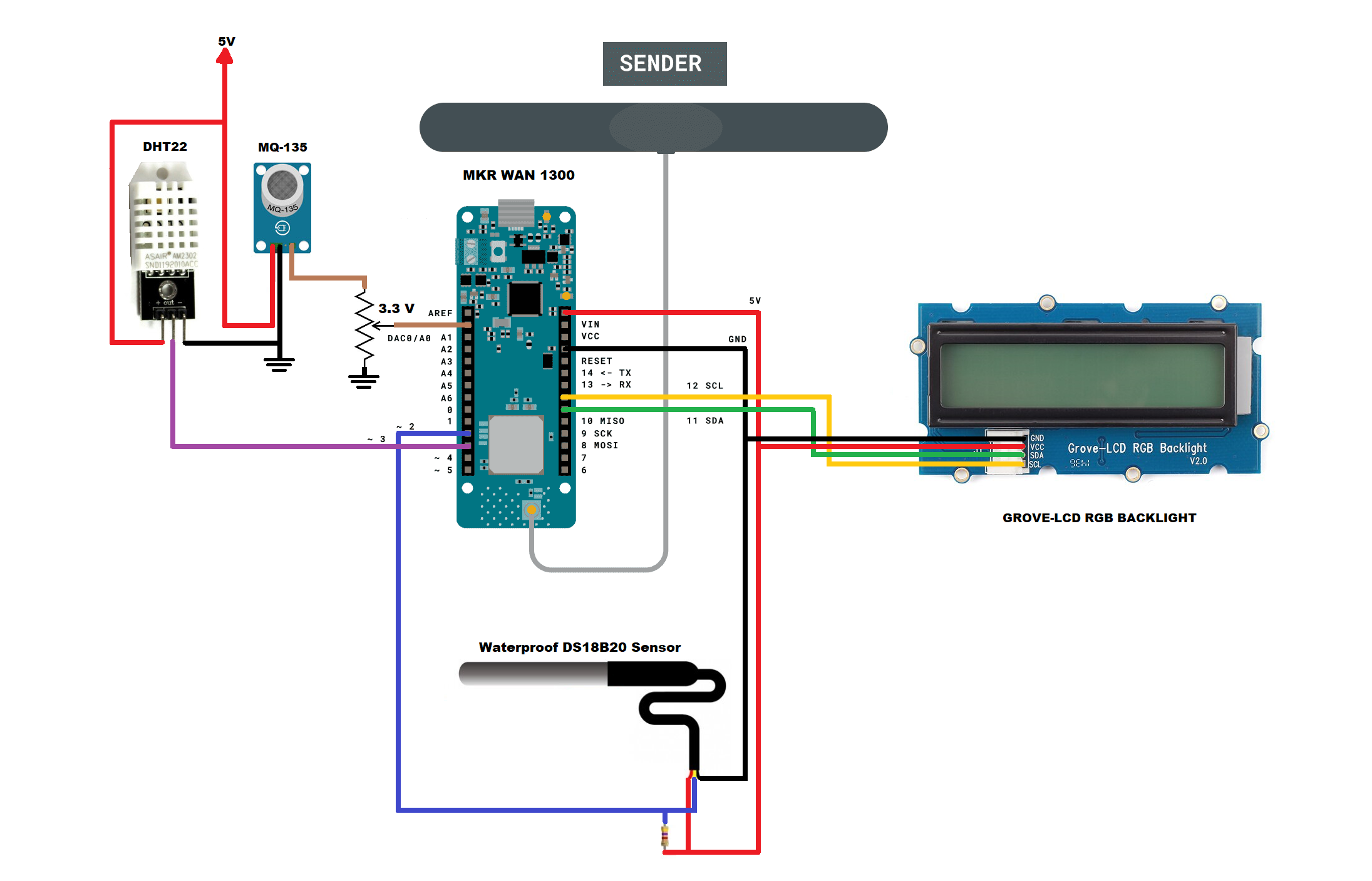
07/26/2022 at 19:52 • 0 commentsTRANSMITTER SCHEMATIC DIAGRAM
In the figure below I show you the electrical diagram of the transmitter after adding the DHT22 humidity sensor and the MQ-135 air quality sensor.
![]()
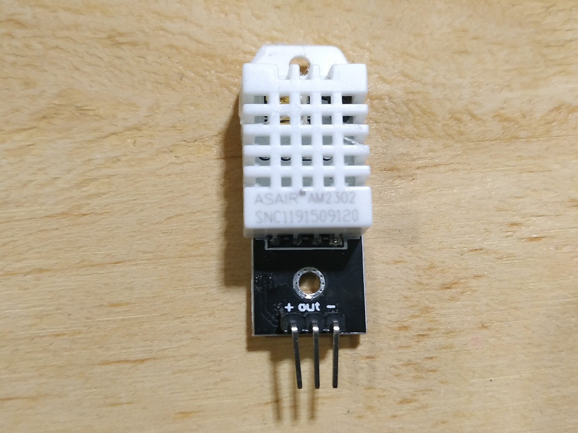
ADDING THE DHT22 SENSOR
In the figure below I show you the DHT22 sensor.
![]()
In this sensor I only obtain humidity readings with value ranges between 0 to 100%. I omit the temperature readings as the DS18B20 temperature sensor has a better measurement range (-55°C to +125°C). You can get the library used to program this sensor here: DHT-sensor-library
ADDING THE MQ-135 SENSOR
In the figure below I show you the MQ-135 sensor.
![]()
Sensitive material of gas sensor is SnO2, which with lower conductivity in clean air. When target pollution gas exists, the sensor’s conductivity gets higher along with the gas concentration rising. Users can convert the change of conductivity to correspond output signal of gas concentration through a simple circuit.
I use this sensor to detect and measure carbon dioxide (CO2) particles in parts per million (ppm). In the following links you can find the reference information and the code to obtain it:
https://github.com/5cottyD/Projects/blob/master/co2ppm_meter.ino
Since these sensors have small differences, I made a small adjustment to this code to calibrate the CO2 level to 0. This is done in the following line of code:
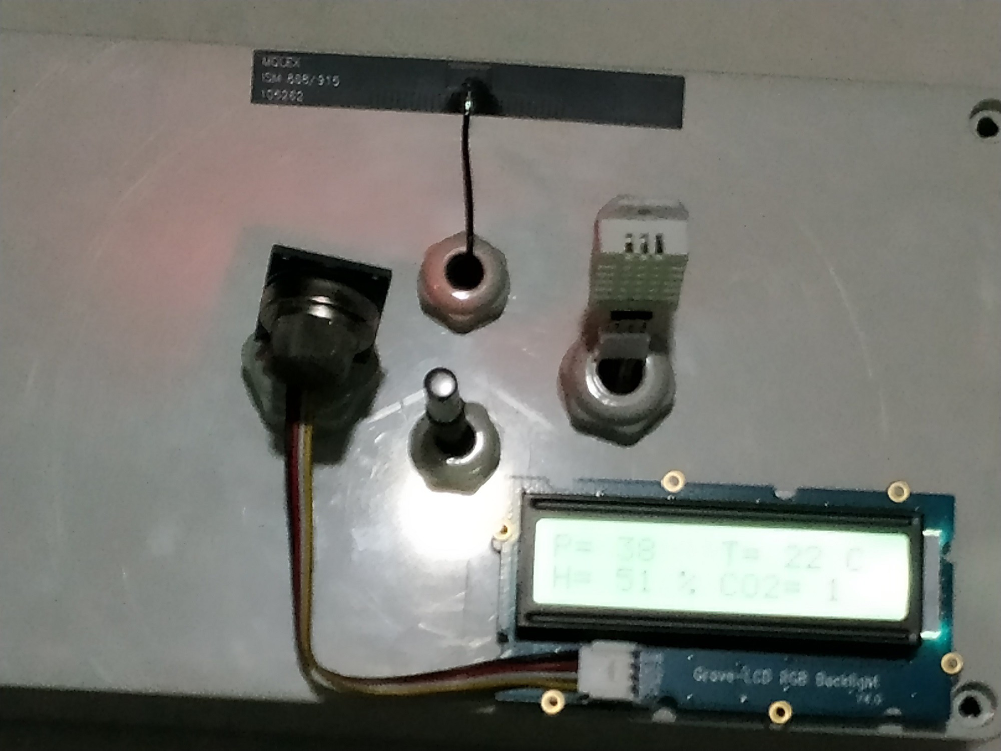
#define co2Zero 55 //calibrated CO2 0 levelAfter mounting the three sensors, the device would look like the image below.
![]()
TRANSMITTER CODE
After adding the DHT22 and MQ-135 sensors, the transmitter code would be as shown below:
LoRaSender_v3.ino
// AUTHOR: GUILLERMO PEREZ GUILLEN

#include <SPI.h> // LoRa->
#include <LoRa.h>
#include <OneWire.h> // DS18B20->
#include <DallasTemperature.h>
#include <Wire.h> // LCD->
#include "rgb_lcd.h"
rgb_lcd lcd;
const int colorR = 173;
const int colorG = 255;
const int colorB = 47;

#include "DHT.h" // DHT22 ->
#define DHTPIN 3    // Pin where the sensor is connected
#define DHTTYPE DHT22   // DHT22 sensor
DHT dht(DHTPIN, DHTTYPE);

// DS18B20-> Data wire is plugged into port 2 on the Arduino
#define ONE_WIRE_BUS 2
OneWire oneWire(ONE_WIRE_BUS);
DallasTemperature sensors(&oneWire);

#define anInput     A0 // MQ135-> analog feed from MQ135
#define co2Zero     0 // calibrated CO2 0 level

int counter = 0;

void setup() {
  // set up the LCD's number of columns and rows:
  lcd.begin(16, 2);
  lcd.setRGB(colorR, colorG, colorB);
  lcd.print("ECOLOGY!");
  pinMode(anInput,INPUT); // MQ135
  lcd.setCursor(0, 1); // LCD
  lcd.print("LoRa Sender");
  if (!LoRa.begin(915E6)) {
  lcd.setCursor(0, 1); // LCD
  lcd.print("Starting LoRa failed!");
    while (1);
  }
  sensors.begin();
  dht.begin();
}

void loop() {
  int co2now[10]; //int array for co2 readings
  int co2raw = 0; //int for raw value of co2
  int co2ppm = 0; //int for calculated ppm
  int zzz = 0; //int for averaging
  for (int x = 0;x<10;x++) // MQ135-> samplpe co2 10x over 2 seconds
  {
    co2now[x]=analogRead(A0);
    delay(200);
  }
  for (int x = 0;x<10;x++) // add samples together
  {
    zzz=zzz + co2now[x];
  }
  co2raw = zzz/10; // divide samples by 10
  co2ppm = co2raw - co2Zero; // get calculated ppm
  if (co2ppm <= 0) {
    co2ppm = 1;
  }
  else {
    co2ppm = co2ppm;
  }
  int h = dht.readHumidity(); //We read the Humidity
  sensors.requestTemperatures();   //The command to read the temperature is sent
  int temp = sensors.getTempCByIndex(0); //The temperature is obtained in ยบC
  // send packet
  LoRa.beginPacket();
  LoRa.print(temp);
  LoRa.print(",");
  LoRa.print(h);
  LoRa.print(",");
  LoRa.print(co2ppm);
  LoRa.endPacket();
  // LCD display data
  lcd.clear();
  lcd.setCursor(0, 0); // LCD
  lcd.print("P=");
  lcd.setCursor(3, 0); // LCD
  lcd.print(counter);
  lcd.setCursor(8, 0); // LCD
  lcd.print("T=");
  lcd.setCursor(11, 0); // LCD
  lcd.print(temp);
  lcd.setCursor(14, 0); // LCD
  lcd.print("C");
  lcd.setCursor(0, 1); // LCD
  lcd.print("H=");
  lcd.setCursor(3, 1); // LCD
  lcd.print(h);
  lcd.setCursor(6, 1); // LCD
  lcd.print("%");
  lcd.setCursor(8, 1); // LCD
  lcd.print("CO2=");
  lcd.setCursor(13, 1); // LCD
  lcd.print(co2ppm);
  counter++;
  delay(2000);
}
As you can see, the data from the three sensors is separated by a comma(",").
-
6. LoRaWAN´s Test with a DS18B20 Sensor
07/26/2022 at 19:39 • 0 commentsBefore doing the field test, I decided to do a basic test indoor in order to correct any hardware or software issues. In the figure below I show you the devices assembled and ready for the basic test.
![]()
In the video below I show you the test inside my house and the system worked without problems.
FIELD TEST
This is the place I chose to work.
![]()
In the image below I show you the transmitter already working.
![]()
In the image below I show you the receiver receiving the data more than 100 meters away from the transmitter.
![]()
Finally, in the video below I show you the tests carried out with this system. This design will serve as an experience to make the system with three sensors and that will be shown in the later chapters.
-
5. Assembling the Receiver
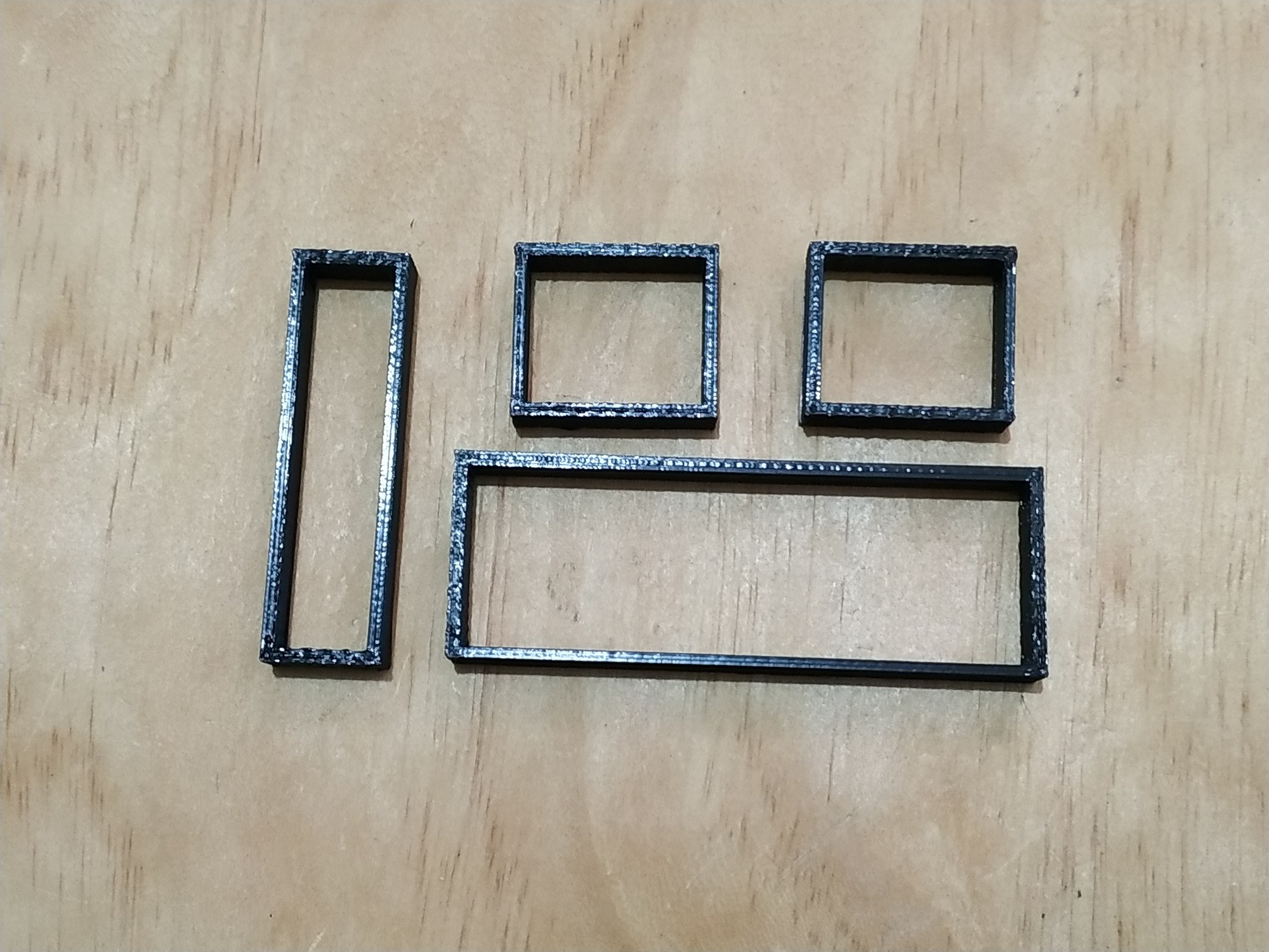
07/26/2022 at 19:35 • 0 commentsIn the figure below I show you the pieces that I print on the 3D printer. These pieces are used to fix the Arduino MKR WAN 1300 board and the LCD display.
![]()
In the image below you can see the assembly of the Arduino MKR WAN 1300 board.
![]()
And now in the image below you can see the assembly of the 20x4 LCD display.
![]()
After fixing the Arduino MKR WAN 1300 board, the 20x4 display, the antenna and the battery; the receiving device looks like the one shown in the figure below.
![]()
As a power supply I used Anker PowerCore II 6700. In addition to providing more accurate voltages, this device gave me better results since it has a power button, a voltage regulator and detects when a device is connected or not.
![]()
I also recommend using a heavy-duty USB to make a good connection
![]()
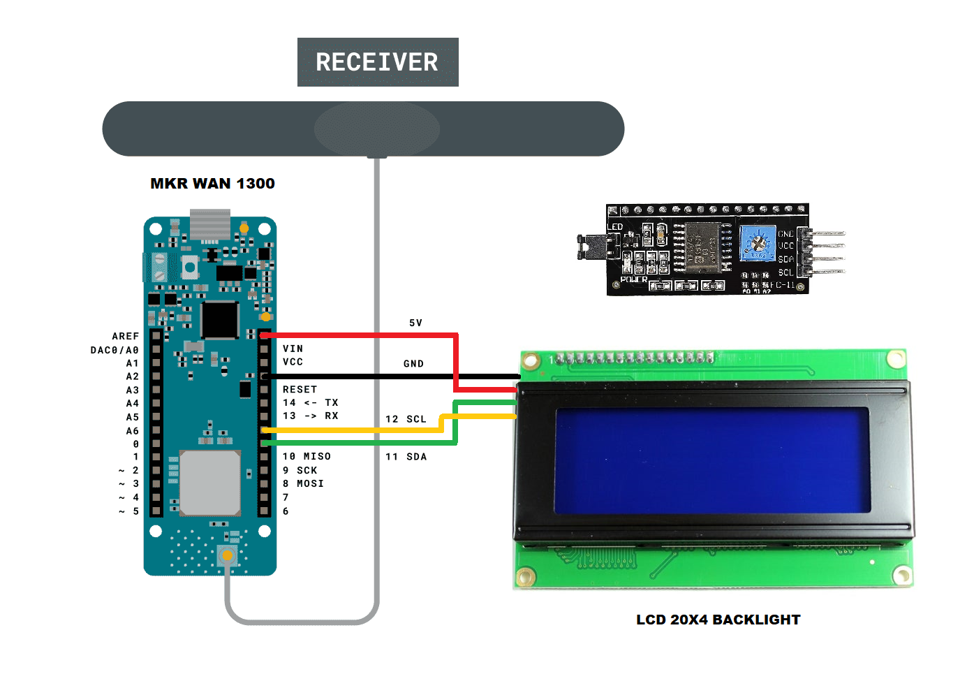
SCHEMATIC DIAGRAM
After adding the 16x2 display, the wiring diagram of the receiver is as shown below.
![]()
CODE
After several attempts to find a library that works well with the Arduino MKR WAN 1300 board, I finally found this one that worked very well for me: LiquidCrystal_I2C
After making these changes, the receiver code is shown below:
LoRaReceiver_v2.ino
// AUTHOR: GUILLERMO PEREZ GUILLEN #include <SPI.h> #include <LoRa.h> #include <Wire.h> // Library for I2C communication #include <LiquidCrystal_I2C.h> // Library for LCD LiquidCrystal_I2C lcd = LiquidCrystal_I2C(0x27, 20, 4); // Change to (0x27,16,2) for 16x2 LCD. char cadena[30]; //We create an array that will store the characters that we will write in the PC console. We assign a limit of characters, in this case 30 byte posicion=0; //Variable to change the position of the characters in the array int valor; //Integer Variable void setup() { lcd.init(); // Initiate the LCD: lcd.backlight(); pinMode(LED_BUILTIN, OUTPUT); Serial.begin(9600); Serial.println("LoRa Receiver"); if (!LoRa.begin(915E6)) { Serial.println("Starting LoRa failed!"); while (1); } } void loop() { // try to parse packet int packetSize = LoRa.parsePacket(); if (packetSize) { memset(cadena, 0,sizeof(cadena));//memset deletes the contents of the array "cadena" from position 0 to the end sizeof // received a packet Serial.print("Received packet... "); // read packet while (LoRa.available()) { char dedos= (char)LoRa.read(); Serial.print(dedos); cadena[posicion]=dedos;//Read a character from the string "cadena" from "posicion", then read the next character with "posicion++" posicion++; } valor=atoi(cadena);//Convert the string to integers Serial.println(); Serial.print(" temp="); Serial.print(valor); posicion=0; // print RSSI of packet int dedal = LoRa.packetRssi(); Serial.print(" with RSSI: "); Serial.println(dedal); lcd.clear(); lcd.setCursor(0, 0); // Set the cursor on the first column and first row. lcd.print("Temp:"); lcd.setCursor(6, 0); lcd.print(valor); lcd.setCursor(0, 2); // Set the cursor on the first column and second row. lcd.print("RSSI:"); lcd.setCursor(5, 2); //Set the cursor on the fifth column and the second row (counting starts at 0!). lcd.print(dedal); digitalWrite(LED_BUILTIN, HIGH); delay(2000); digitalWrite(LED_BUILTIN, LOW); } } -
4. Assembling the Transmitter
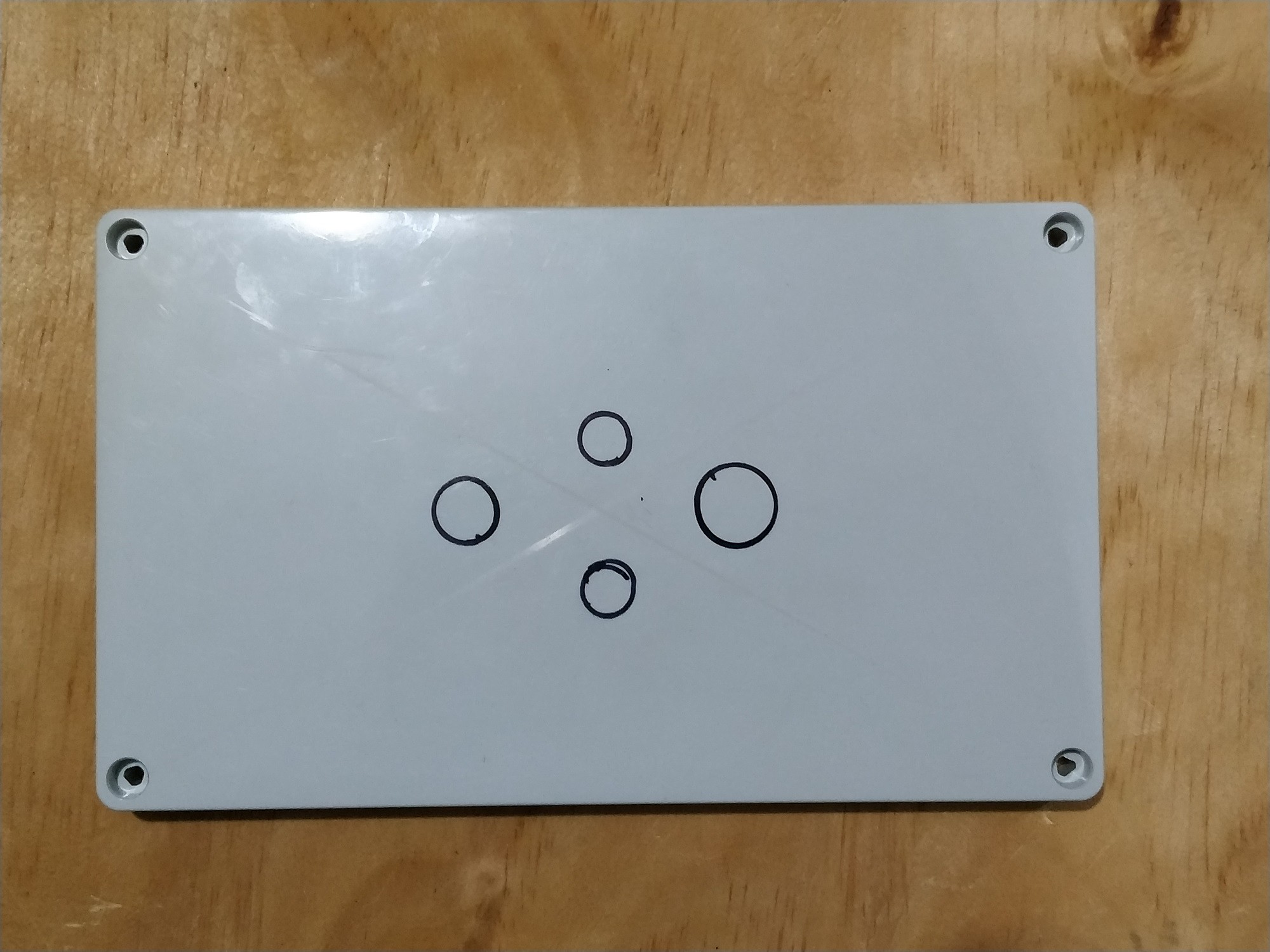
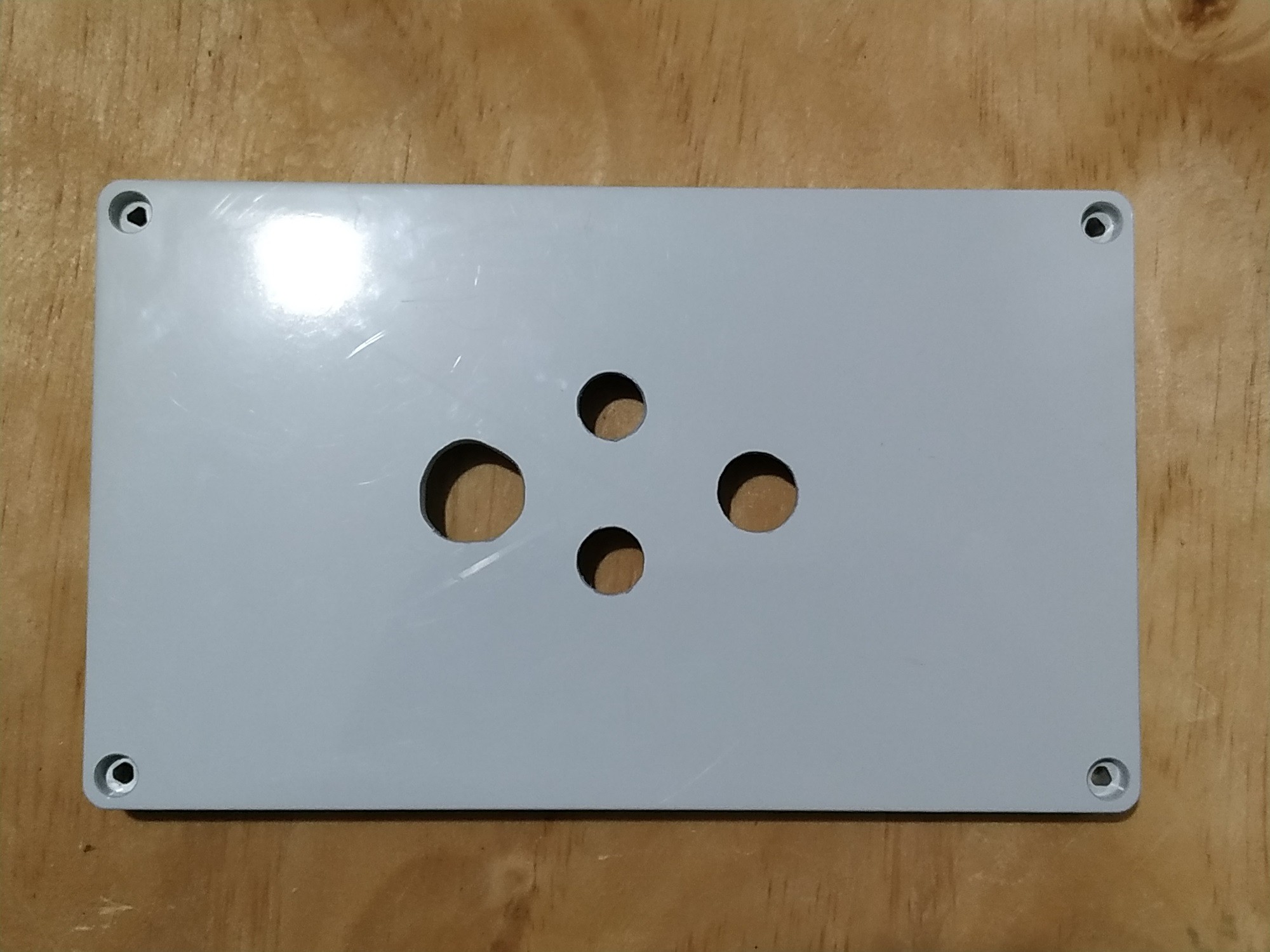
07/26/2022 at 19:30 • 0 commentsIn the figure below I show the lid of the box to make the marks for the drill holes.
![]()
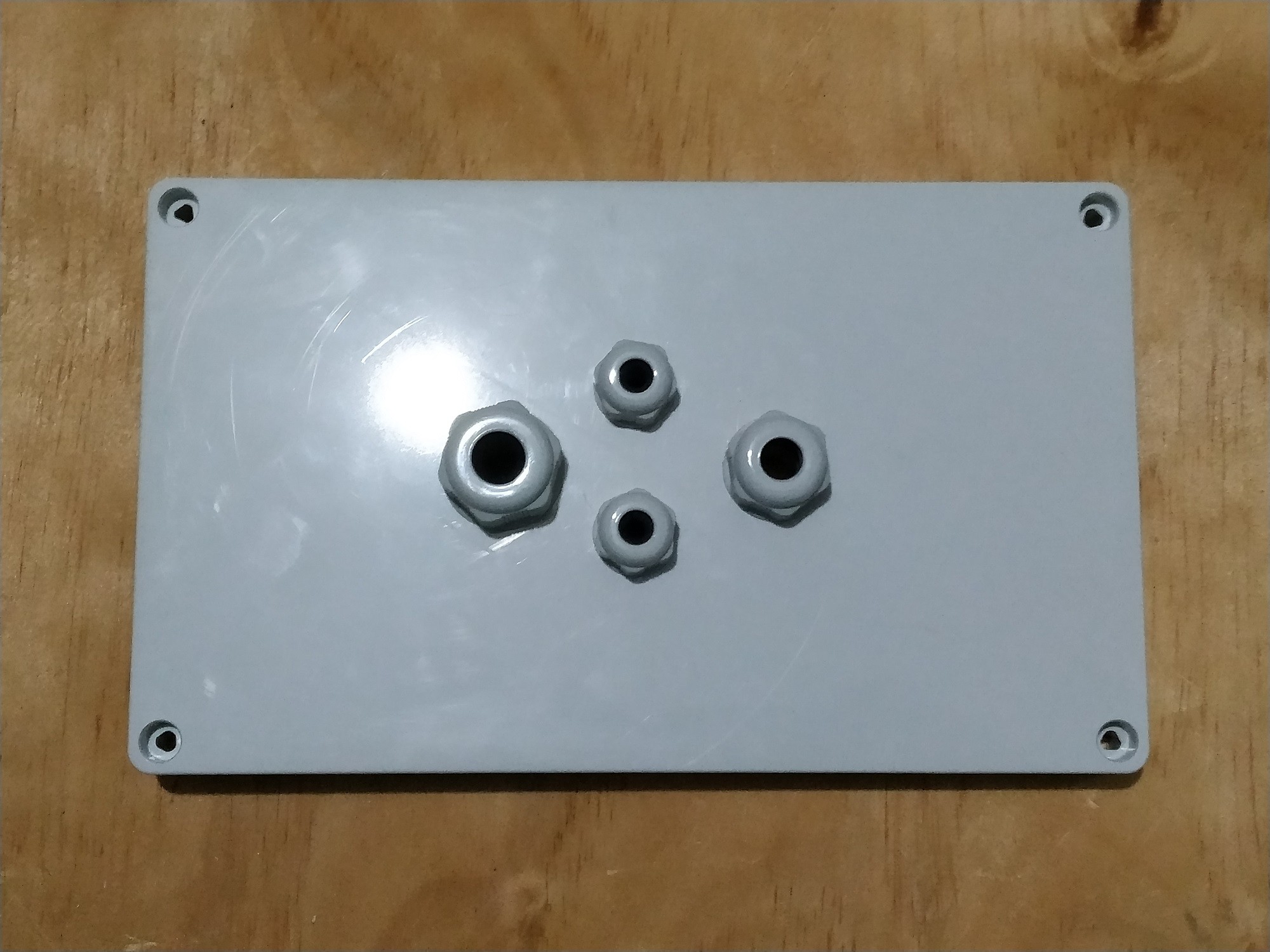
Now below we see how this piece was after drilling.
![]()
Once the holes are large enough, then it's time to attach the connectors.
![]()
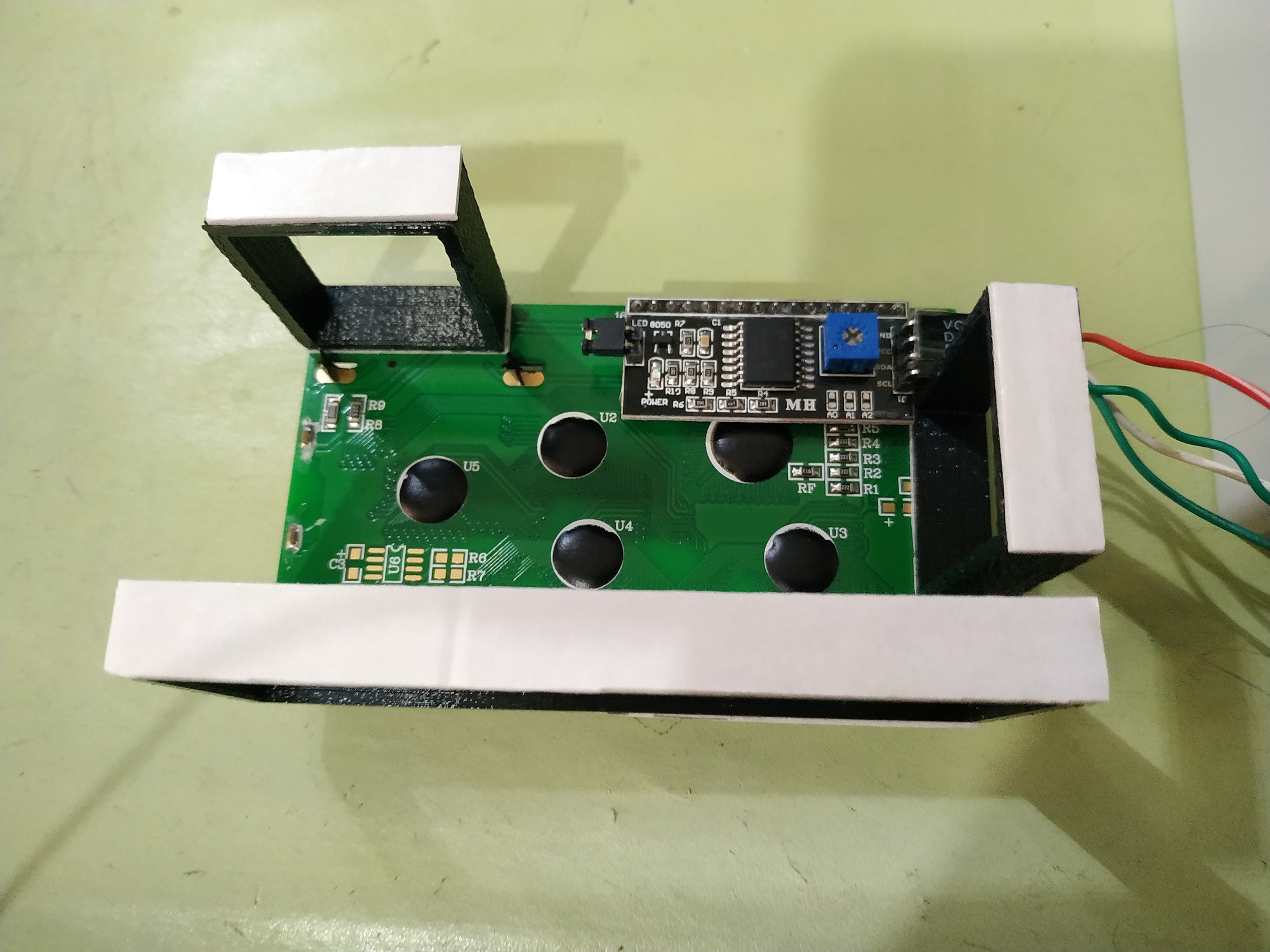
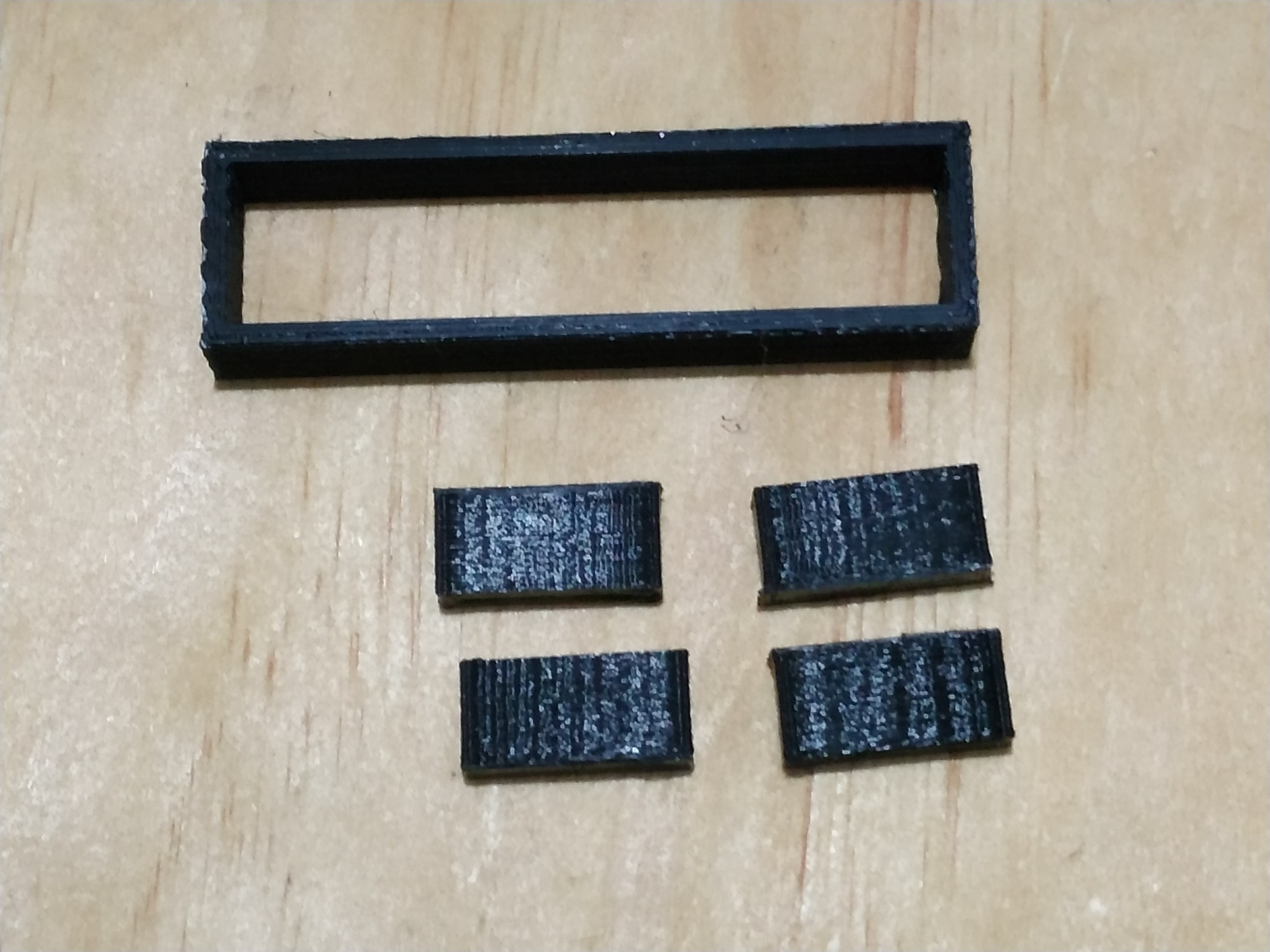
In the figure below I show you the pieces that I print on the 3D printer. These pieces are used to fix the Arduino MKR WAN 1300 board and the LCD display.
![]()
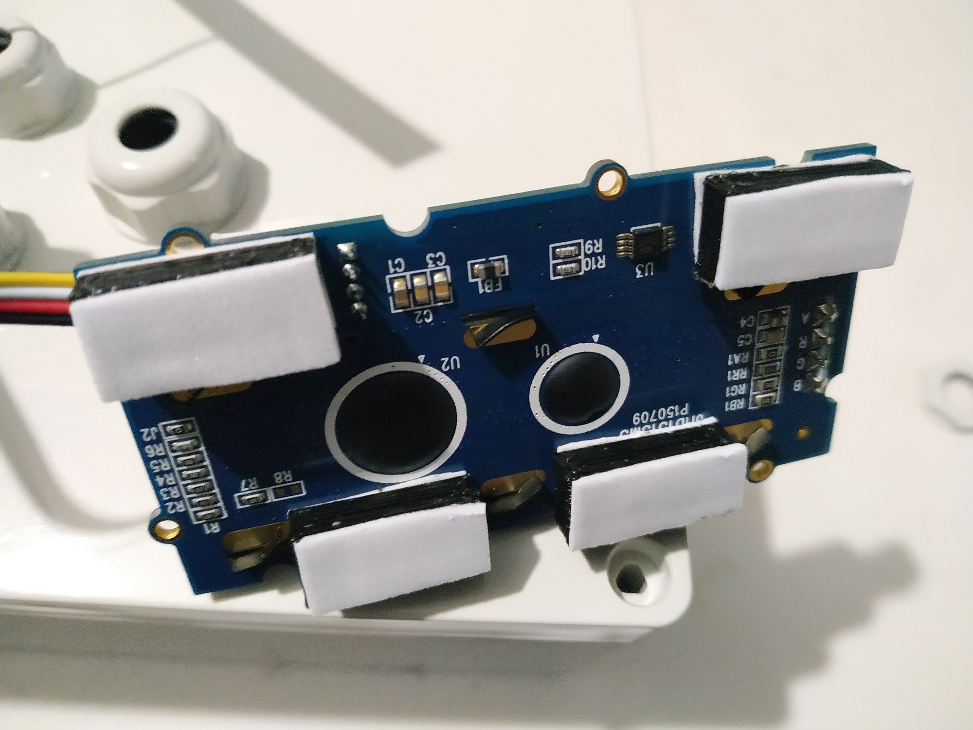
In the image below you can see how to assemble the 16x2 LCD display that comes in the kit.
![]()
Then we fix the Arduino MKR WAN 1300 board, the 16x2 LCD display, the DS18B20 sensor and the antenna.
![]()
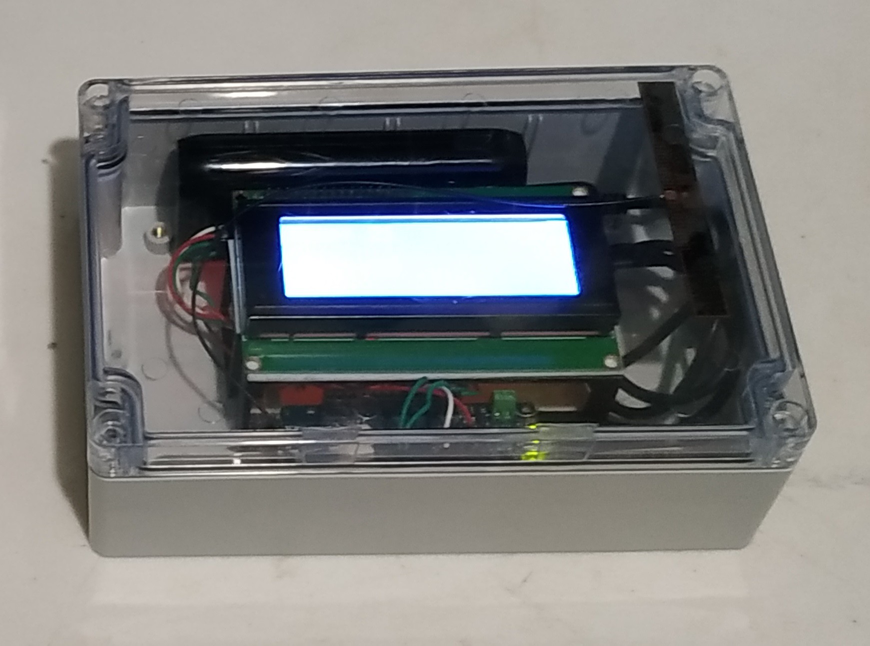
The transmitter would look like the figure below.
![]()
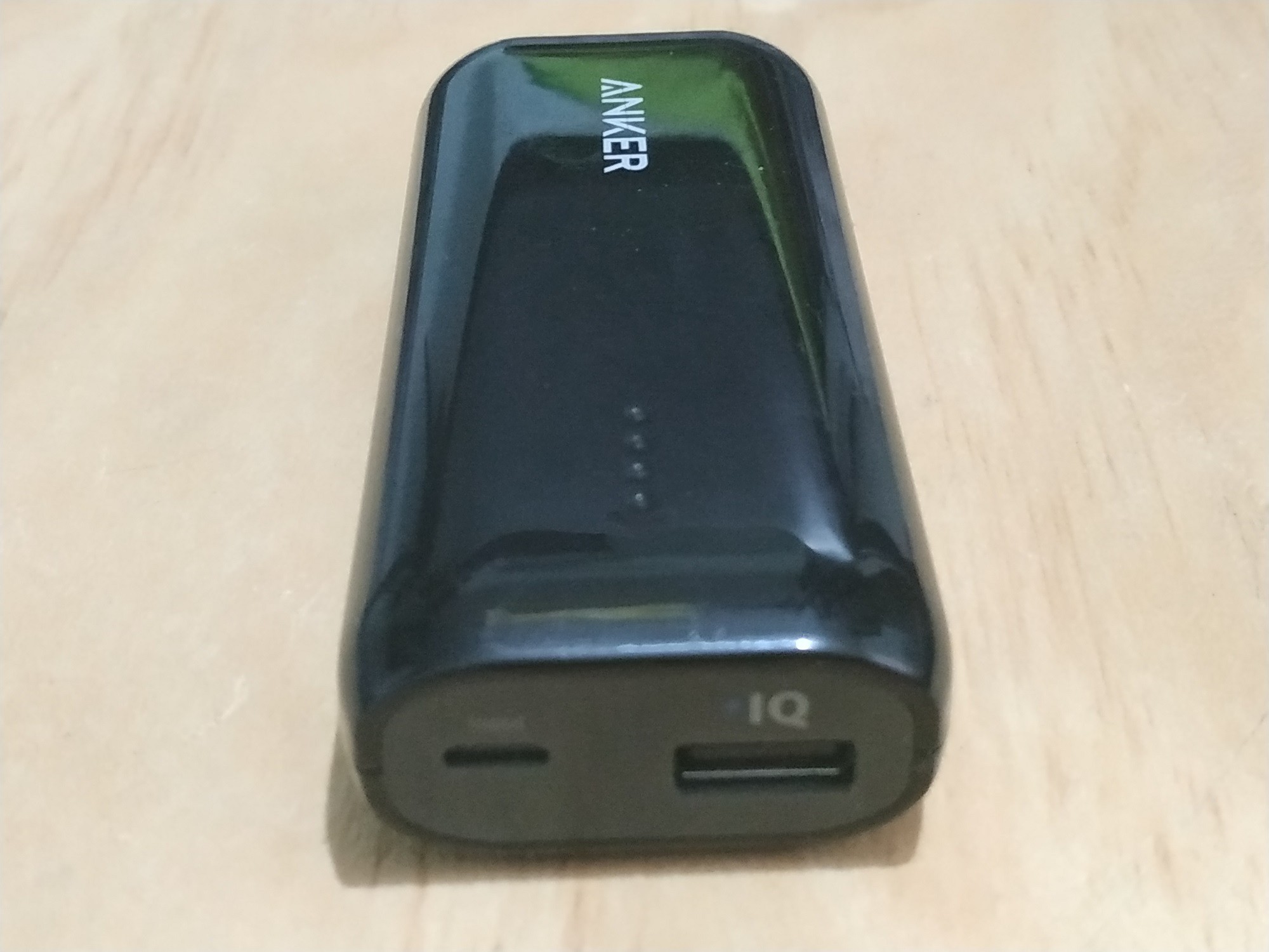
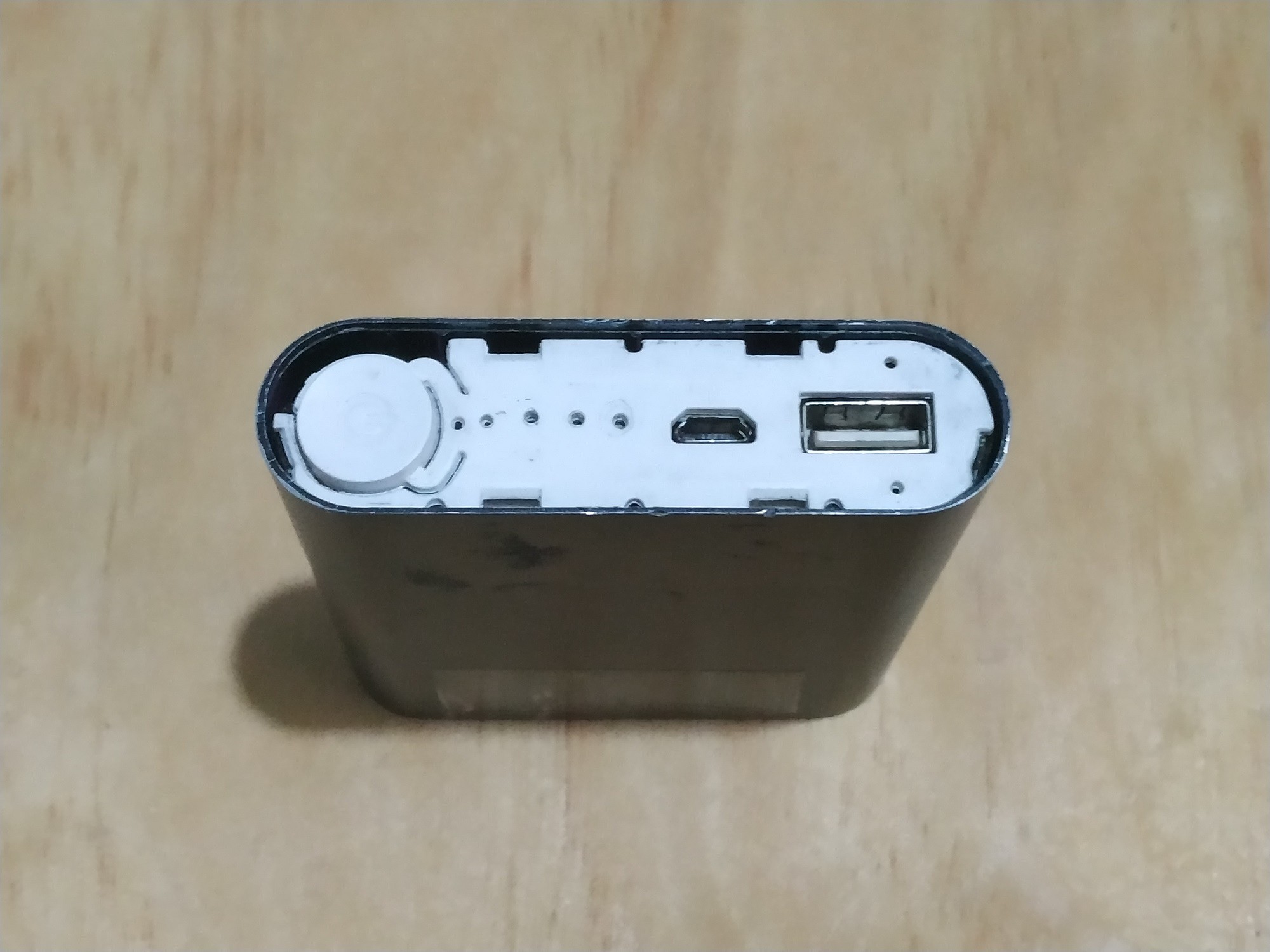
As a power supply I used a generic 5V Portable Charger Power Bank 16800 mAh. In addition to providing more accurate voltages, this device gave me better results since it has a power button, a voltage regulator and detects when a device is connected or not.
![]()
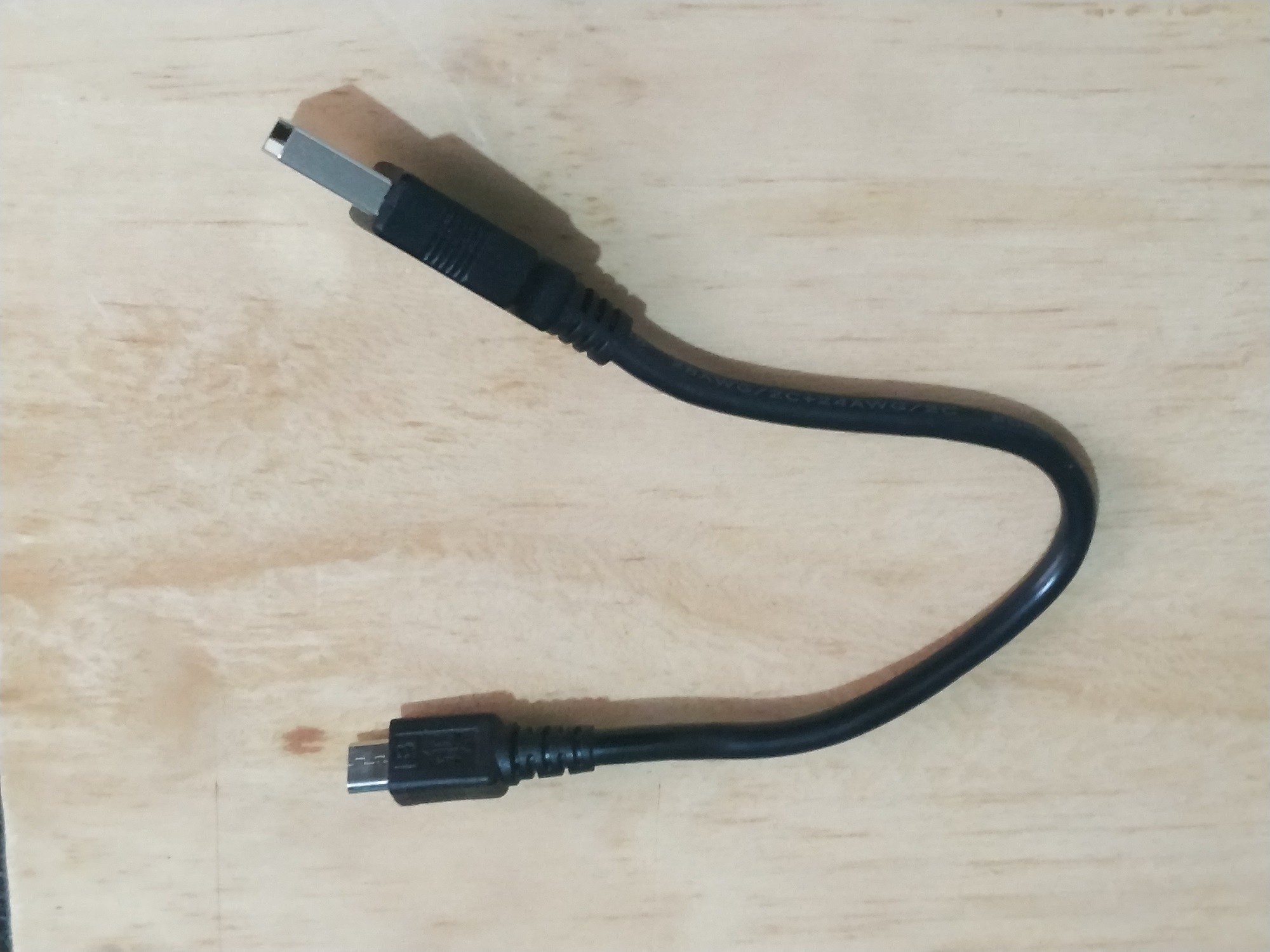
I also recommend using a heavy-duty USB to make a good connection
![]()
SCHEMATIC DIAGRAM
After adding the 16x2 display, the wiring diagram of the receiver is as shown below.
![]()
CODE
All the information needed to install the library you can get in this link: Grove-LCD RGB Backlight Library from Github
After making these changes, the transmitter code is shown below:
LoRaSender_v2.ino
// AUTHOR: GUILLERMO PEREZ GUILLEN

#include <SPI.h>
#include <LoRa.h>
#include <OneWire.h> // DS1B20->
#include <DallasTemperature.h>
#include <Wire.h> // LCD->
#include "rgb_lcd.h"
rgb_lcd lcd;
const int colorR = 173;
const int colorG = 255;
const int colorB = 47;

// Data wire is plugged into port 2 on the Arduino
#define ONE_WIRE_BUS 2
// Setup a oneWire instance to communicate with any OneWire devices (not just Maxim/Dallas temperature ICs)
OneWire oneWire(ONE_WIRE_BUS);
// Pass our oneWire reference to Dallas Temperature.
DallasTemperature sensors(&oneWire);

int counter = 0;

void setup() {
  // set up the LCD's number of columns and rows:
  lcd.begin(16, 2);
  lcd.setRGB(colorR, colorG, colorB);
  // Print a message to the LCD.
  lcd.print("ECOLOGY!");
  lcd.setCursor(0, 1); // LCD
  lcd.print("LoRa Sender");
  if (!LoRa.begin(915E6)) {
  lcd.setCursor(0, 1); // LCD
  lcd.print("Starting LoRa failed!");
    while (1);
  }
  sensors.begin();
}

void loop() {
  sensors.requestTemperatures();   //The command to read the temperature is sent
  int temp= sensors.getTempCByIndex(0); //The temperature is obtained in ยบC
  lcd.clear();
  lcd.setCursor(0, 0); // LCD
  lcd.print("Packet:");
  lcd.setCursor(8, 0); // LCD
  lcd.print(counter);
  lcd.setCursor(0, 1); // LCD
  lcd.print("Temp:");
  lcd.setCursor(8, 1); // LCD
  lcd.print(temp);
  // send packet
  LoRa.beginPacket();
  LoRa.print(temp);
  LoRa.endPacket();
  counter++;
  delay(4000);
}
Environmental Toolkit for an Ecological Area
LoRaWAN IoT system with the Arduino MKR WAN 1300, that help my community to monitor the air quality and water of our ecological area