 jasonwinfieldnz
-
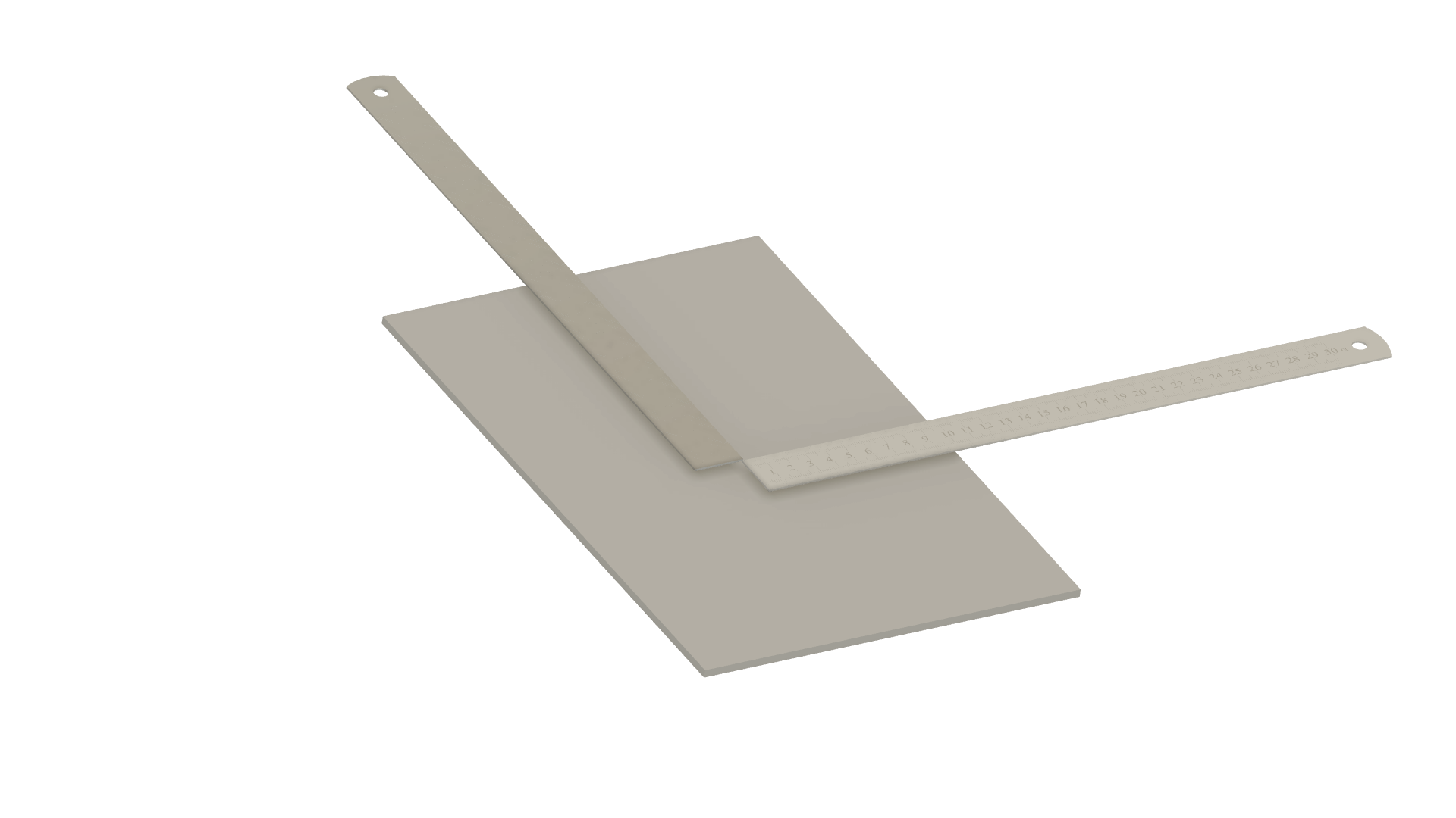
11Drill hole for cutting wire
![]()
Mark this same distance out on the top board and drill a 12mm hole.
-
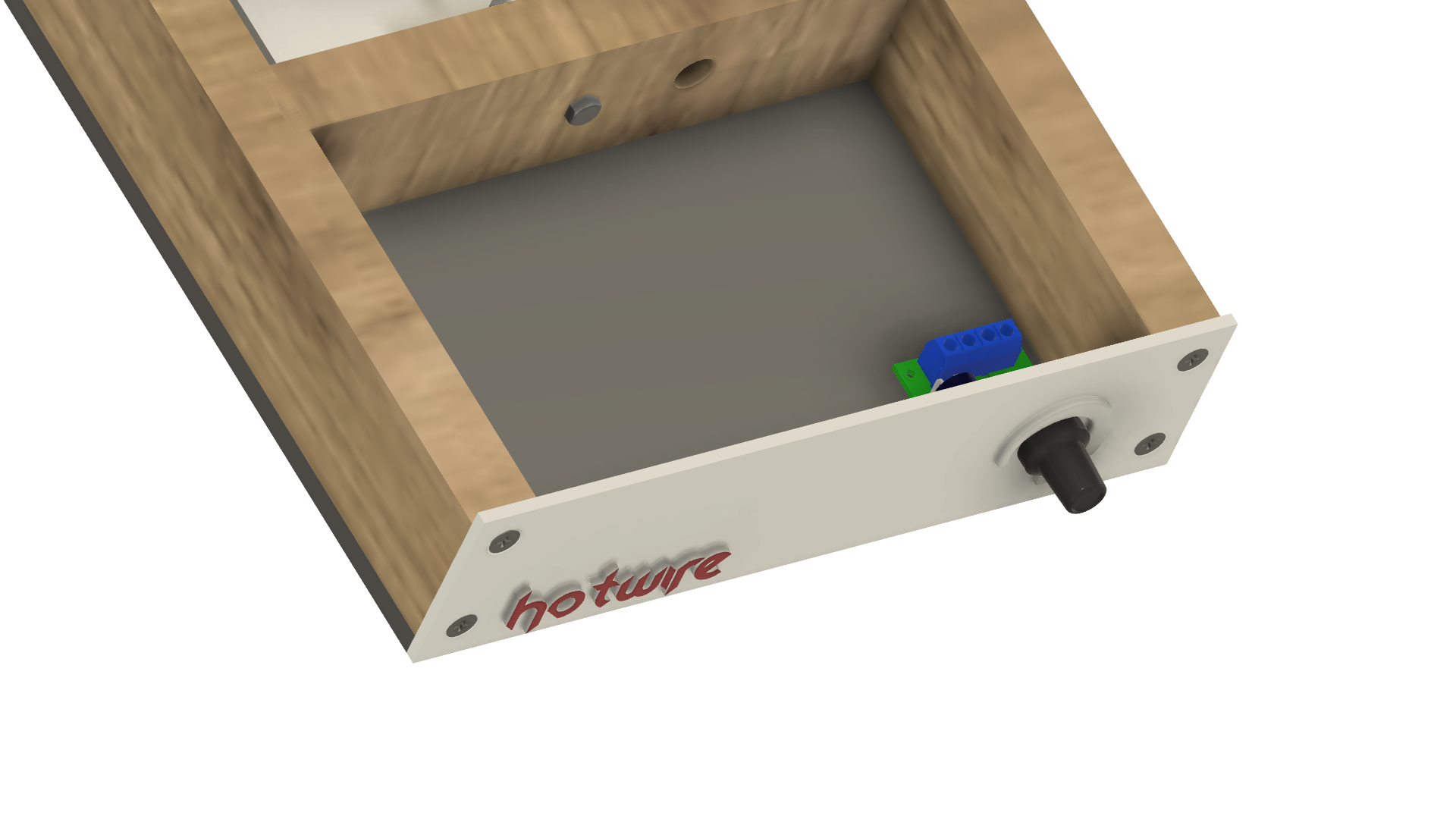
12Install front facia
![]()
Screw in the front facia and check the speed controller for enough space.
-
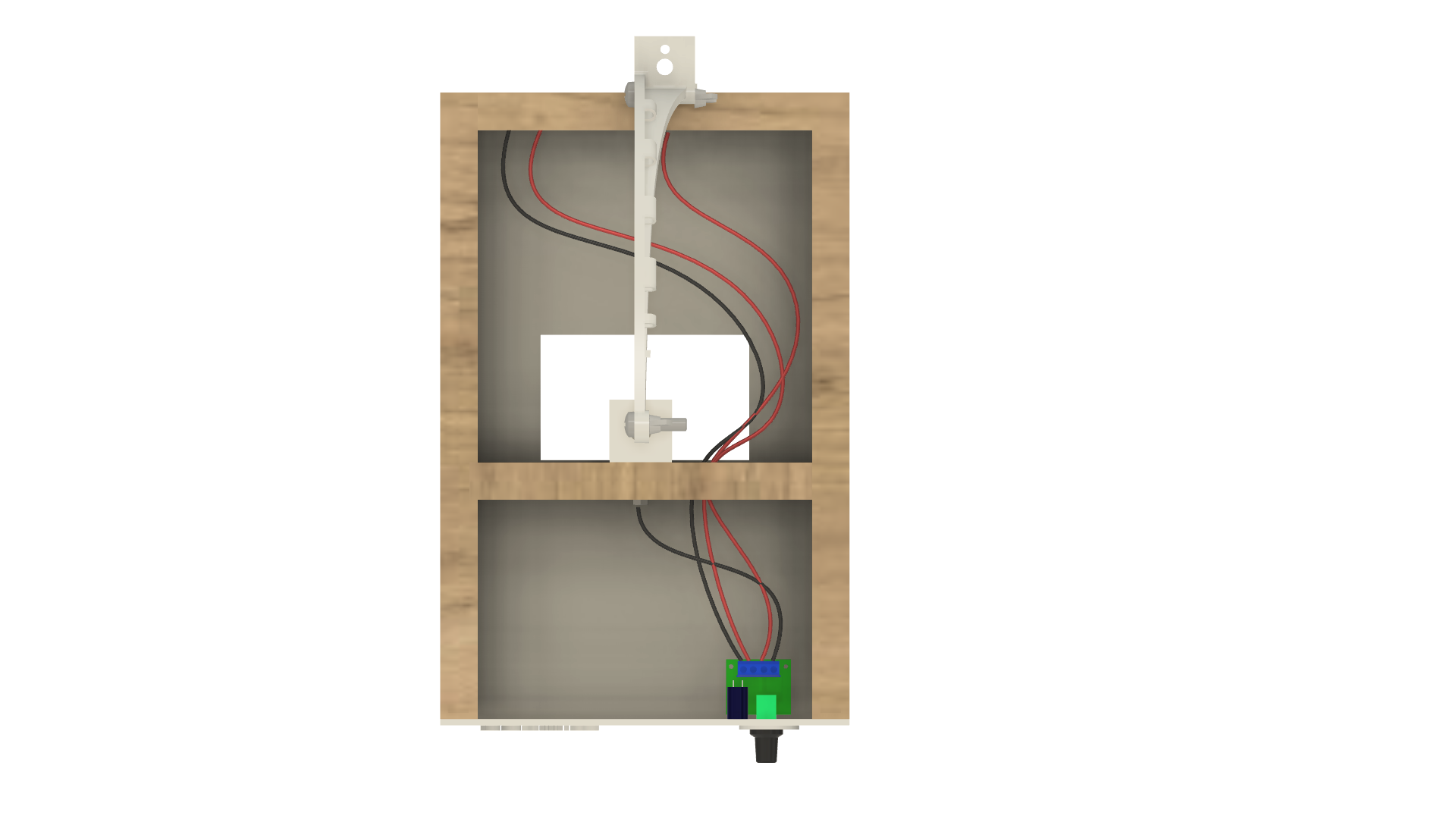
13Install wiring
![]()
Run the positive and negative wires from the back of the frame to the speed controller input. Check your speed controller as the contacts can vary. Run the negative wire from the output to the bottom tension bolt. Run the positive wire from the output of the speed controller to the back of the frame through the hole drilled earlier.
-
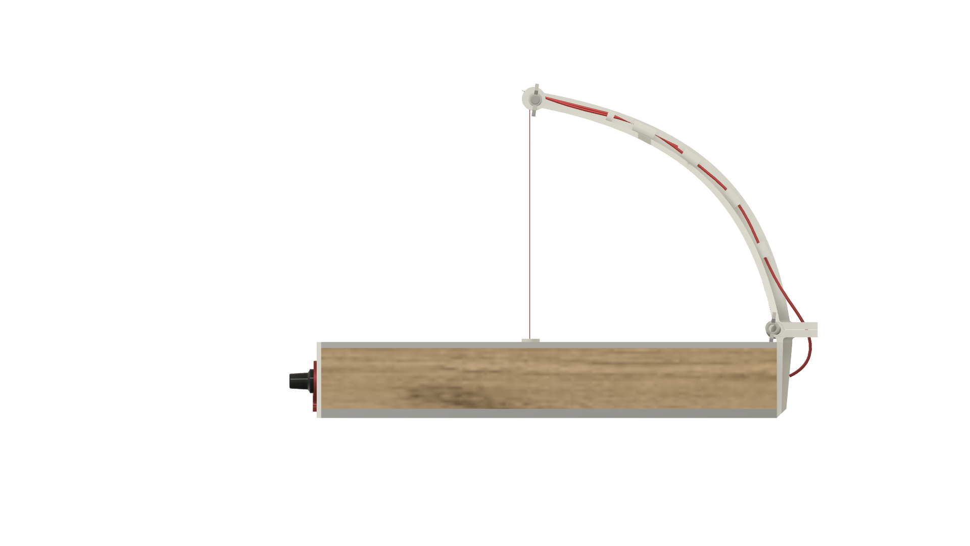
14Run wire to the top of the bow.
![]()
Run the wire from the back of the frame to the top of the bow.
-
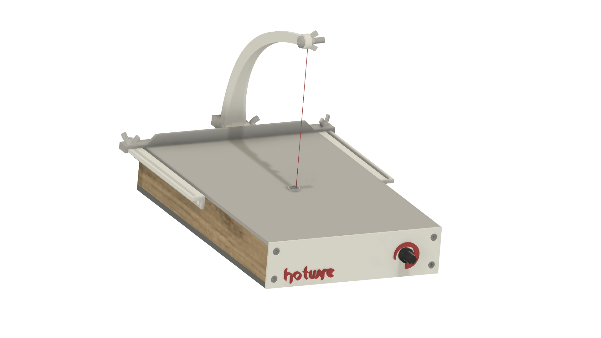
15Final assembly
![]()
Remove the cutting wire and place the top cover, screw this down in place. The bottom tension point can now be moved in place. Screw two further wood screws on either side of the mounting plate to fix it in position. Place a 10mm washer inside the top of the bottom mounting plate. This prevents the wire from cutting the PLA/ABS when it is pushed against it.
Attach the guide rails to the back of the frame using the remaining screws and wingnuts.
-
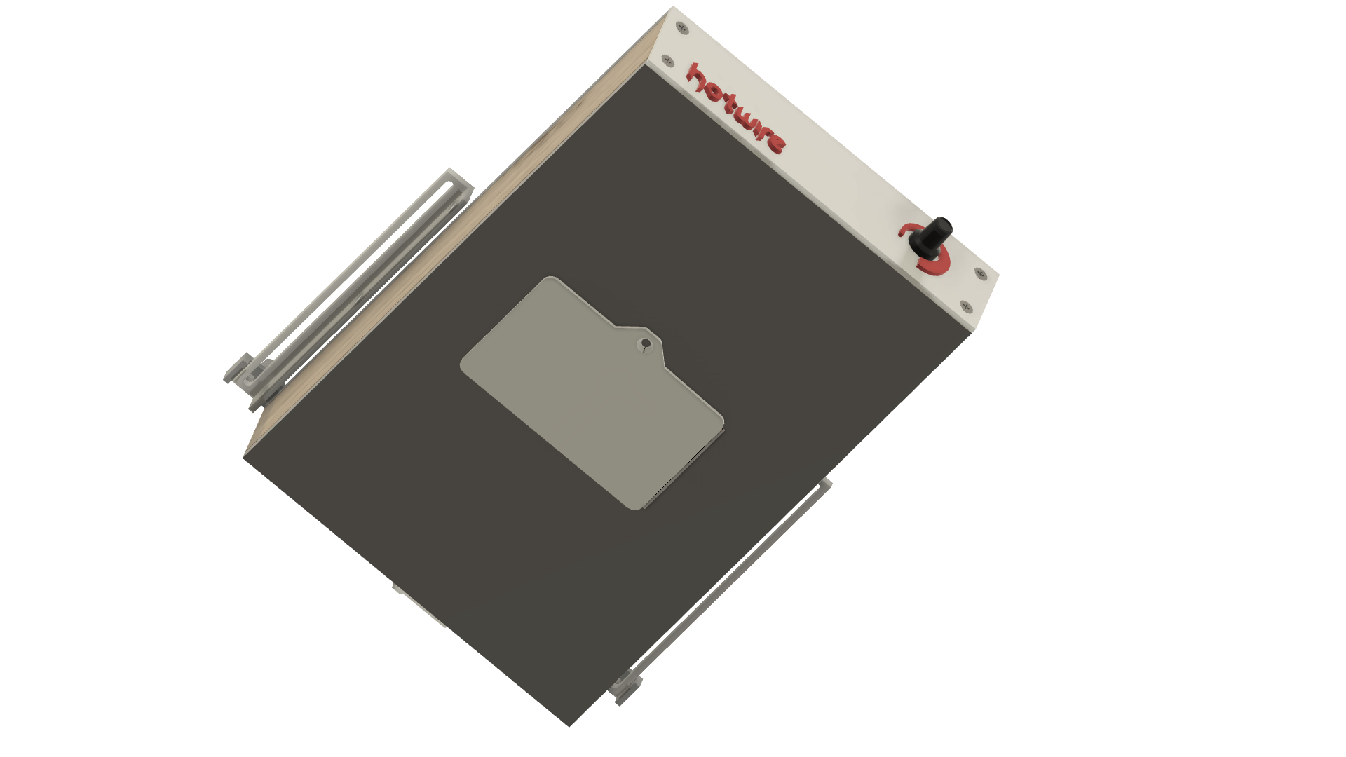
16Install bottom cover.
![]()
Lastly, place the bottom inspection panel on and rubber feet on each corner.
-
17Operation
Run 12V from a computer power supply to the terminals at the back of the frame.
Check my video but essentially you turn your speed controller up until it cuts the material you are using. It generally doesn't take much power to do this.
Move the guides back and forward to get the thickness you need.
When not in use always drop the bow down to prevent any tension from being lost and easy storage.
Super simple foam cutter
This hotwire cutter uses a PC power supply and no spring to cut foam and polystyrenes.
Discussions
Become a Hackaday.io Member
Create an account to leave a comment. Already have an account? Log In.