 Robin Dorst
I haven't done a ton of so if you have any ideas/improvements I always love to learn and improve.
Downloads of the datasheets for the inverter and databox as well as the software used to control it can be found here.
Software
When plugging in to the computer the data box shows up as a "Prolific USB-to-Serail Comm Port" with a baud rate of 9600.
I have tried various programs but haven't found something to listen to the serial communication between the data box and the computer without blocking its own program NETMS to still talk to it.
The next step I will try is to make a cable with the data lines exposed so I can use a logic analyzer to listen in.
Or maybe someone else knows a better software?
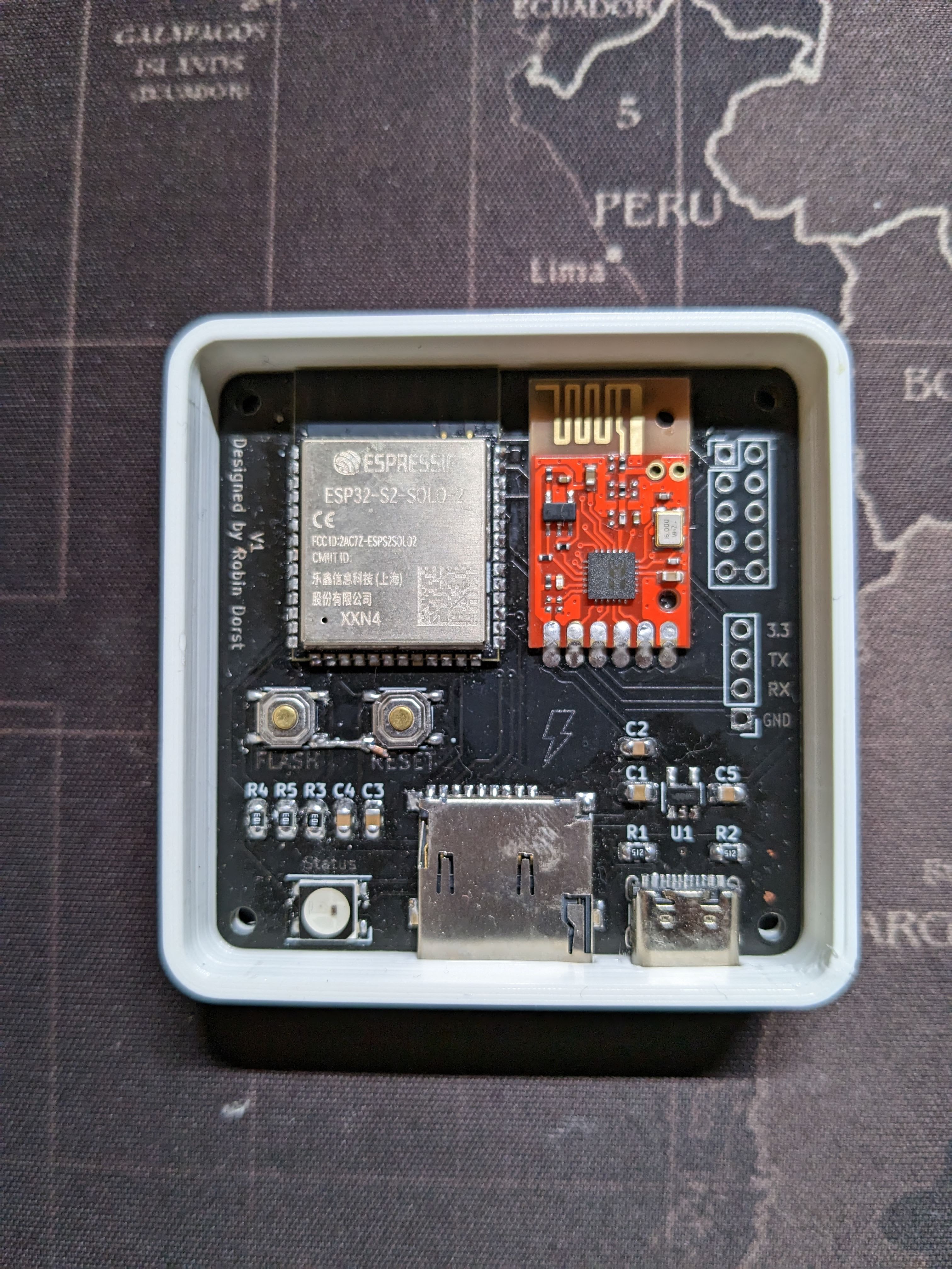
Hardware
The hardware is quite simple and only consists of a single PCB with a pic16f1947 microcontroller and a LC12S off the shelf 2.4Ghz wireless module. The external antenna is only necessary with the case on or for greater distances.
Some more useful links about the LC12S module:
https://www.iot-rf.com/2.4g-uart-wireless-module-bk2461.html
https://forum.arduino.cc/t/lc12s-explained/695700/3
https://www.satistronics.com/shop/product/180300-lc12s-uart-wireless-serial-transparent-transmition-128-channel-module-9312
http://arduinolab.pw/index.php/2016/11/13/radiomoduli-na-24ggc-c-uart-interfejsom-lc12s/
http://user.cavenet.com/jgurley/lc12s/
https://www.pcbway.com/project/shareproject/LC12S_wireless_transceiver_module.html
I have already tied into the communication between microcontroller and wireless module and have successfully decoded the signal transmitted by the databox in order to get a response from a specific inverter. The inverter is selected by an id written on its backside. This is also the id entered in the software NETMS to add a new inverter. Check out the decoded Signals on the first project log.
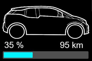
I have successfully decoded most of the signals and managed to send the data to a database as well as visualize it with influxdb v2 build in dashboard. The next step for me is to package the hardware into a neat little box maybe even with a custom pcb and then I'm done.
I was also thinking about packaging everything into a single box, either with a rpi zero w that is doing the communication with the transceiver, db and data visualization on some web interface
OR
add a SD card to the esp have it store all the data on there and host a lightweight web interface displaying the current values and a short history.
Please give me feedback about what you would like to see or even use in your own setup.


 stefan.schnitzer
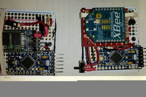
 Dimitris Andritsakis
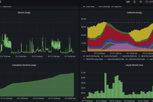
 Jacob David C Cunningham
Hi, have the same inverter with databox. think the last two numbers could be some kinde of checksum?! any other ideas?