Close
0%
0%

Jelly

A minimal DIY 8-bit CPU made with TTL chips, to perform native brainfu*k language, extended to use three sequential access tapes.

Public Chat
Similar projects worth following
Jelly:

How make a new cpu without memory address access, using only sequential access, for code, data and input/output ?

I want to learn about how old cpus are made by inside and understand about signals, gates, latches, pipelines, TTLs etc.

Jelly runs a minimal language, brainfunk*, a superset of brainfuck, a minimal Turing-complete programming language, which works with sequential access to two infinite tapes, just moving forwards or backwards.

But Jelly include few new commands to self.

Jelly is in the third revision.

image:
https://en.freejpg.com.ar/free/info/100024149/jelly-fish-blue-water-background-sea-ocean-animal

Disclaimer:

I'm a passionate hobbist with interest in digital electronics,
This project is about practicing and learning.
This is a personal project, with entertaining and educational objectives.

Jelly

** This is still a brainstorm, I'm a newbie in TTL circuits **

most updates at: https://github.com/agsb/jelly/tree/main

What is it ?

Jelly is a concept, a alternative computer with a diferent paradigm, not for performance but for design.

Jelly uses two ideal tapes, first for code (aka ONE),  second for data (aka TWO) and a standart input and output device.

Any memory device could emulate a tape.

About op-codes

At first, lets resume the 16 opcodes for Jelly brainfunk;


ascii    
action
origin            
details
1    
>forward move tape one position
brainfu*konly data tape
2
<backward move tape one position
brainfu*konly data tape
3
+increment byte at tape position
brainfu*konly data tape
4
-decrement byte at tape position
brainfu*konly data tape
5
.output a byte at tape position
brainfu*kfrom data tape into standart output
6
,input a byte to tape position
brainfu*kfrom standart input into data tape
7
[test if byte at data tape is zero, and forward code tape to matched ]brainfu*kallow 255 nested loops
8
]test if byte at data tape is not zero, and backward code tape to matched [
brainfu*kallow 255 nested loops
9
!halt
Jelly            
 end of code
0
=
do nothing
Jelly
nop
10=reserved
jellynop
11=
reserved
jellynop
12=
reserved
jellynop
13=
reserved
jellynop
14=
reserved
jellynop
15 
=
reservedjellynop
anynopjelly
nop

PS: 03/07/2023 table changed

jelly-six.dig

last update, halt circuit included

- 122.33 kB - 02/03/2023 at 13:34

Download

jelly-six-tape.dig

generic pseudo tape

dig - 26.75 kB - 02/03/2023 at 13:19

Download

jelly-six-halt.dig

added halt state

dig - 739.34 kB - 02/03/2023 at 11:40

Download

jelly-two-halt.png

control logic steps for halt and flag signals

Portable Network Graphics (PNG) - 155.63 kB - 09/12/2022 at 14:24

Preview

jelly-two.dig

full bare bones circuit for Jelly

dig - 91.02 kB - 09/12/2022 at 14:24

Download

View all 9 files

  • 2 × at28c16 2k * 8 Memory ICs / EEPROMs
  • 3 × 74hc574 8 x D-register, with 3-state, clock, output enable
  • 1 × 74hc393 Logic ICs / Counters
  • 2 × 74HC245 Bi-direcional 8-bit switch
  • 1 × 74HC74 Dual D-Flip-flop

View all 12 components

  • revision for easy

    Alvaro Barcellos07/04/2023 at 14:05 0 comments

    New revision for Jelly. Changes in concepts, circuits and complexity.


    Executing:

    Jelly does all external communication using 8 lines of control and 8 lines for information, the control lines are output and information is bi-directional. 

    The standart input and output are instant devices.

    Changed to two modes, code and loop. In code mode, all operations except begin '[' and
    again ']' are done. In loop mode, just run forward or backward until find a match again ']' or begin '['. While in loop mode, the math circuit is used as loop counter.

    The fetch of next code byte from code tape, aka nop, now is op-code 0x0 and automagic, called by a clear on opcode latch and on step counter;

    Circuits:

    Changed the input latches to 74hc273, with reset and clock. This solves, 'how easy do a fetch' and  'how clear loop counter'.

    Include output latches as 74hc574, with output enable and clock, for device control and control 3-state access internal data bus;

    Include a bi-directional switch 74HC245, with enable, direction and 3-state. This solves external devices access to internal data bus;

    Logics:

    A loop logic circuit does all logics for start and stop the loop mode;

    The loop logic circuit now have signals: begin, again, zero, mode, move, and generates do_mode and do_move.

    begin is a line, high when data byte is a '[' and mode is code;

    again is a line, high when data byte is a ']' and mode is code;

    zero is a line, high when data byte is not a zero;

    mode is a line, high when mode is loop;

    move is a line, high when movement is reversed;

    domode is a toggle, low when mode is code, high when mode is loop; 

    domove is a toggle, low when forward, high when backward;


    idbeginagainzeromodemovedomodedomove
    11000010
    20110011
    3xx01010
    4xx01111

     
    - A toggle is a pulse in the clock line of D-flip-flop.

     - The do_mode also does initial reset of counter circuit.

     - The code mode movement is always forward.

     - The loop mode ends when counter is zero.

     - The X is does not matter.

  • begin and again as loop

    Alvaro Barcellos06/20/2023 at 22:10 0 comments

    How To

    All Jelly opcodes are easy implemented except loops. the [ and ],  refered  as begin and again, keep me in a round-robin by months without a feasible solution.

    As  pseudo-code, there are three groups of actions, for simplify, I call as page zero, page one and page two.

    In page zero, all opcodes are executed and when a begin occurs and data is zero that clear a counter and change to page one, when a again occurs and data is not zero that clear  a counter and change to page two.

    In page one, when found a begin increase a counter, when found a again decrease a counter,  then moves code tape forward and if counter is zero change to page 0.

    In page two, when found a begin increase a counter, when found a again decrease a counter, then moves code tape backward and if counter is zero change to page 0.

    Since no data is read while in page one or two, the circuit of U7, U2, U8 is used as counter


    Make It

    the solution was make  true-table for lines and states.

    begin is a line set high when code is [

    again is a line set high when code is ]

    zero is a line set high when data is non zero

    page 1 is the address A9 line for eeproms U1 and U2

    page 2 is the address A10 line for eeproms U1 and U2

    flip 1 is the clock for D-Flip-FLop the control the address A9 line

    flip 2 is the clock for D-Flip-FLop the control the address A10 line

    when page 2 is set the movement is backward.


    Table 1 - lines and states for loops

    outputoutput
    begin [
    ] againzeropage 1
    page 2
     FLIP  1
    FLIP 2
    results
    0001010toggle page 1
    0000101toggle page 2
    1000010toggle page 1
    0110001toggle page 2
    0011000forward
    0010100backward
    1001000count + 1
    1011000count + 1
    0101000count - 1
    0111000count - 1
    1000100count + 1
    1010100count + 1
    0100100count - 1
    01101

    00count - 1

  • rewinds to forwards

    Alvaro Barcellos02/12/2023 at 01:21 0 comments

    I'm doing a review of control lines, as jelly-six circuit get closer to go wire-wrap.

    An alternative is resume dual function lines as:


    TABLE U1, does internal control

    U1 Lines
    actiondescription
    D0M0, address A8 for U4 (eeprom math)
    vide table U4
    D1M1, address A9 for U4 (eeprom math)
    vide table U4
    D2M2, address A10 for U4 (eeprom math)
    vide table U4
    D3CP5, clock (CP) for U5 (74hc574 latch)push a value into U5
    D4OE2,  output enable for U2 (eeprom tape control)pull a value from U2
    D5CP6, clock (CP) for U6 (74hc574 latch)push a value into U6
    D6OE4,  output enable for U4 (eeprom math control)pull a value from U4
    D7reserved

    TABLE U2, does tapes control

    U2 Linesactiondescription
    L0, L1
    00 is none, 01 is ONE, 10 is TWO, 11 is BOB
    select which tape (none, one, data, bob)
    L20 is forward (FW), 1 is backward (BK)
    select the direction of step
    L30 is read (RD), 1 is write (WR)
    select the action
    L4reserved

    L5reserved

    L6reserved
    L7reserved

    TABLE U2 special

    special status, L0, L1, L2, L3
    action
    0000does nothing
    used as delay
    0010toggle a flip-flop to exchange forward and backward
    does toggle tape (ONE or TWO) swap
    used for extend exchange values
    0001toggle a flip-flop to exchange tape ONE and tape TWO
    does toggle direction (FW or BK) swap
    used for solve loops
    0011


    TABLE U4, Math Control,

    value (M0,M1,M2)operationvalueresult
    0copy 00011011 00011011
    1increase0001101100011100
    2decrease0001101100011010
    3clear0001101100000000
    4shift left
    0001101100110110
    5shift rigth
    0001101100001101
    6negate0001101111100100
    7mirror0001101111011000

  • Still in progress

    Alvaro Barcellos02/02/2023 at 13:05 0 comments

    This project is still waiting pieces to born in hardware.

    While I'm learning about 6502 circuits and Forths, searching options to emulate the 3 tapes for Jelly.

    Use of common SRAM and FLASH memories is in the stream, but Jelly have no concept of address, just increase or decrease a stream.

    Could be a pack of counters as 74hc193, using 4 to 16 address bits of memory, limits to 64 kb both memories, and minimal logic for decode up or down.

    And leds, many leds...

  • why brainfunk ?

    Alvaro Barcellos10/04/2022 at 18:15 0 comments

    Why chose brainfunck ?

    Why not a common "if branch return" operation language as many designs ?

    Because Becker and Gottschlich does " AI Programmer: Autonomously Creating Software Programs Using Genetic Algorithms ", [https://arxiv.org/abs/1709.05703] using brainfuck. More information in [http://brainfuck.org/]

    And Mazonka and Christofani, made a complete brainfuck interpreter written in brainfuck. https://github.com/maksimKorzh/dbfi/blob/master/self-interpreter-paper.pdf

    Some brainfuck tutorial and more, some algorithms.


  • minimal Jelly

    Alvaro Barcellos09/15/2022 at 16:28 0 comments

    "Something in the way, she is moving"

    Looking at circuits done in Digital application,  Jelly could be more simple.

    There are one circuit with a eeprom to control tape devices, and two  circuits between a buffer (74hc574) to a eeprom (at28c16).

    For the tape circuit, just need control the OE of eeprom.

    For the code circuit, just need control CE of buffer.

    For the math circuit, with feedback, need control CE of buffer and OE of eeprom.

    All others signal of CE, OE, inside closed circuits, goes enabled forever.

    These simplify control signals to CE1, OE2, CE3, OE4, plus M1, M2 for 4 operations math, plus A8 and A9 for 4 pages extended.

    (These changes are in file jelly-six.dig).

    As some combinations of signals for tape devices are also used to setup flags as swap, move and halt, need some complementary logics.

    (These changes are in file jelly-six-halt.dig).

    "Something in the way, she moves"

  • loops without jumps

    Alvaro Barcellos09/09/2022 at 13:02 0 comments

    Jelly must have some external logic to complement FSM eeproms.

    The way found to simulate an "IF" or "ELSE" was to change the "page", depending on external conditions.

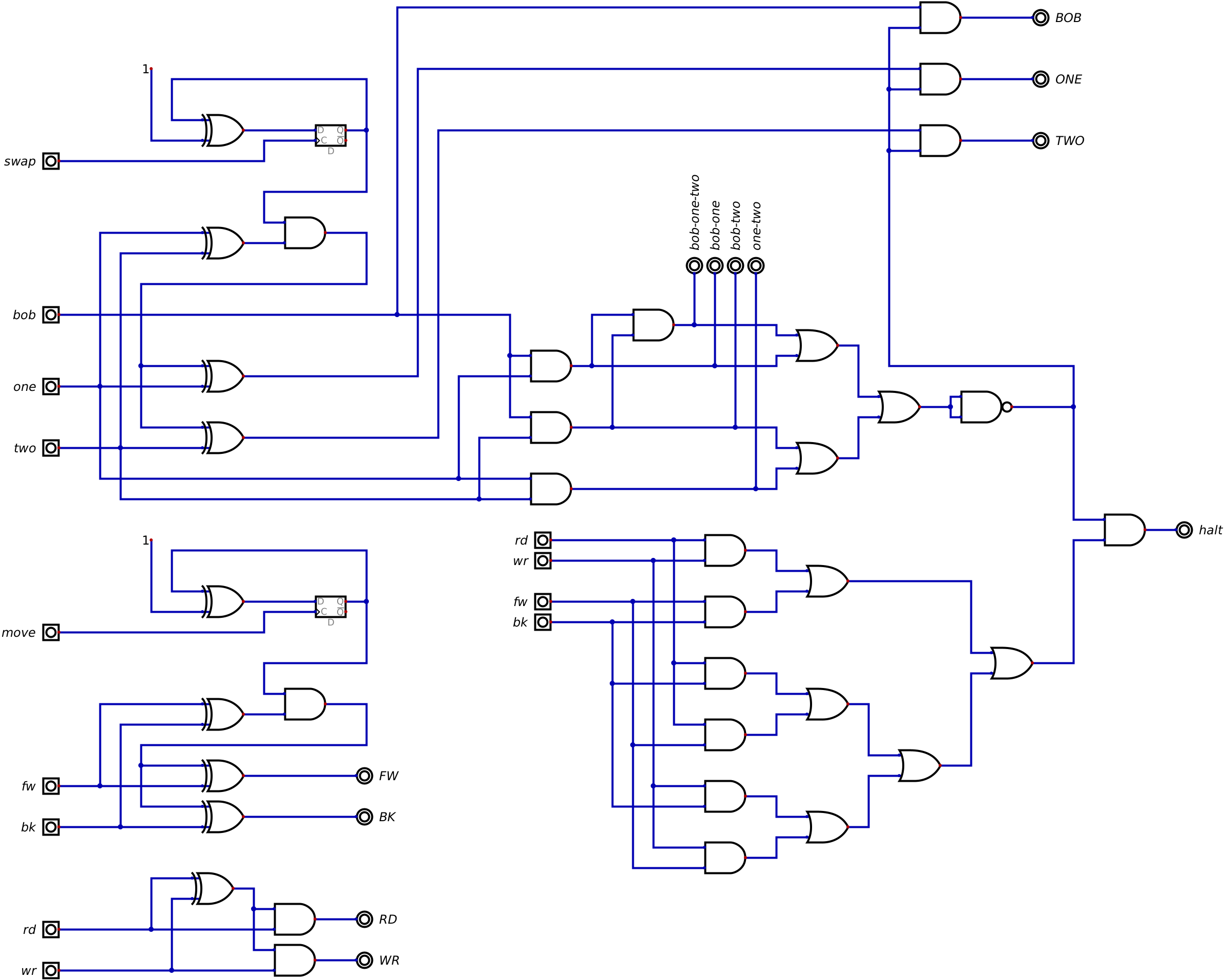
    Circuits define "check and clear" logic. For bob, one, two signals, when two are active they are used to validate the conditions. For signals fw, bk, rd, wr, which cannot be active simultaneously.

    The one and two signals are used to activate the swap signal, which works like a toggle switch that inverts the selection between one and two.

    The bob and one signals are used to activate the move signal, which works like a toggle switch that inverts the selection between move forward or backward. This is needed to simplify the loop logic.

    The bob and two signals are used with the zero signal to select "page one" by activating a  toggle switch for address a08. In the "page one" commands just executes a next opcode, else [ and ], that increase or decrease a counter.

    The pseudo code for processing [ and ] loops in "page one" :

    for ( ; ; ) {
          if (c==[) cnt++;
          if (c==]) cnt--;
          if (cnt == 0) break;
          c = next();
    }

    PS.

    the next action is a tape bob sequence of  move and read. move could be forward or backward. the move signal toggles setup direction and both could be coded as a single operation move.

    the logic circuit is showed in file jelly-two-halt.dig

    -- this still a stub ---

    the conditions table of loops [ and ] could be resumed as

    case
    page
    loop
    conditionaction
    10[zero == NO
    next
    20[zero  == YES
    go page 1
    31[zero == NO
    inc count, next
    41[zero == YES
    inc count, next
    50]zero == NO
    go page 1
    60]zero == YES
    next
    71]zero == NO
    dec count,  prev
    81]zero == YES
    go page 0

  • How make it

    Alvaro Barcellos09/06/2022 at 21:01 0 comments

    Good news.

    Going through lists of TTLs and cpus and diy homebrew projects, I have a good feeling that I'm not doing anything very different than what has already been done for different purposes.

    Using eeproms to save logic by defining FSM to control the signals, aka microcode, is common practice. Use 3-state latchs to isolate shared data bus, ditto. Use counters to synchronize pipeline phases, ditto. Use eeprom to define the results of mathematical operations, ditto.

    I still need to figure out how to process flags, state toggles and other synchronisms.

    All the TTL chip circuits have arrived, so I can start building and testing.

    First, I need to build an eeproms programmer, see eepromgrammer.

    some links for same uses.

    http://www.bigmessowires.com/nibbler/

    https://github.com/Turing6502/TuringSAP1

    https://tomnisbet.github.io/nqsap/

    The Mark One computer also have a opcode set very like Jelly one's.

    http://www.aholme.co.uk/Mk1/Architecture.htm

  • Jelly as a HRM

    Alvaro Barcellos08/31/2022 at 16:10 0 comments

    Today, I discover about "Human Resource Machine",  (https://tomorrowcorporation.com/humanresourcemachine) by  https://github.com/adumont/hrm-cpuhttps://github.com/nrkn/hrm-cpu and https://spectrum.ieee.org/three-computer-games-that-make-assembly-language-fun.

    The hrm-cpu is a "human" sequential machine, with restrict set of instructions, very like as Jelly's ones.

    The HRM literal jumps behave as BF loops \[ and \] and  the HRM literal bumps behave as BF  \+ and \-.  Add and Sub are trivial.

    Jelly can process as a 8-bit HRM, using ten or more i/o tape cells as internal storage and few macros.


  • Maths

    Alvaro Barcellos08/25/2022 at 14:48 0 comments

     Jelly have a change in signals for  fake ALU eeprom.

     Now the low byte address is the argument and high byte address is the operation.

     Only unary math are allowed, and using address A08, A09, A10, the operations are:

    high byte (page)
    operationexample
    000clear
    (00011011 => 00000000)
    100increase
    (00011011 => 00011100)
    010decrease
    (00011011 => 00011010)
    110copy
    (00011011 => 00011011)
    001negate
    (00011011 => 11100100)
    101shift left
    (00011011 => 00110110)
    011shift right
    (00011011 => 00001101)
    111mirror
    (00011011 => 11011000)

    Only clear, increase, decrease and copy are current in Jelly.

    PS. mirror is reverse bit order, as from little endian into big endian and vice-versa.

View all 20 project logs

Enjoy this project?

Share

Discussions

Similar Projects

Does this project spark your interest?

Become a member to follow this project and never miss any updates