-
1Print 3D parts
Print the provided 3D files
-
2Insert switches and encoders
Tolerances are tight enough so that they can all be friction fitted
-
3Wire parts
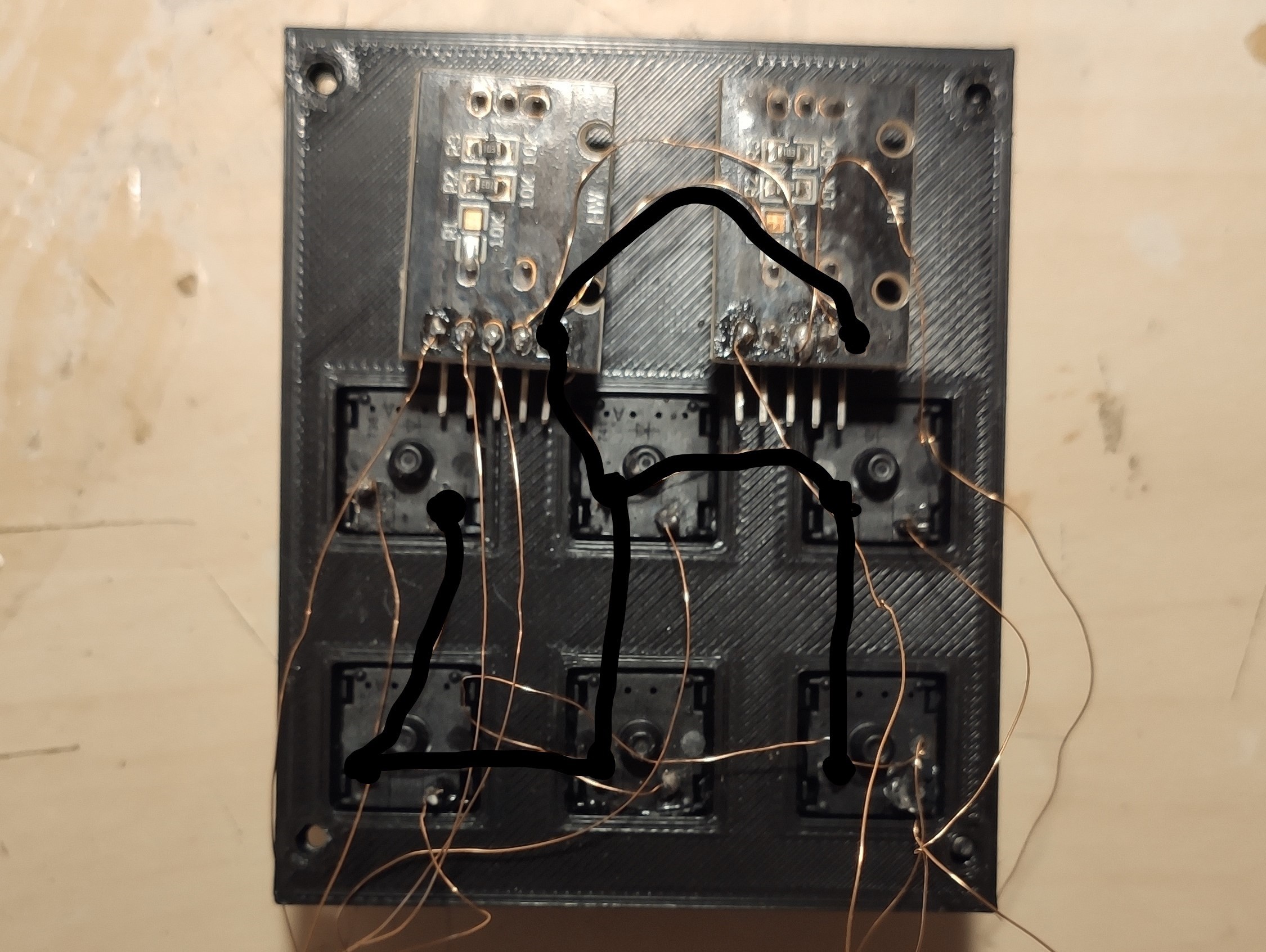
Wire the grounds of the encoders together with the copper wire (make sure to heat the ends of the cable to remove the enamel) and wire it with one pin of the switches so they all have a common ground.
![]()
Solder the 5V pins of the encoders together.
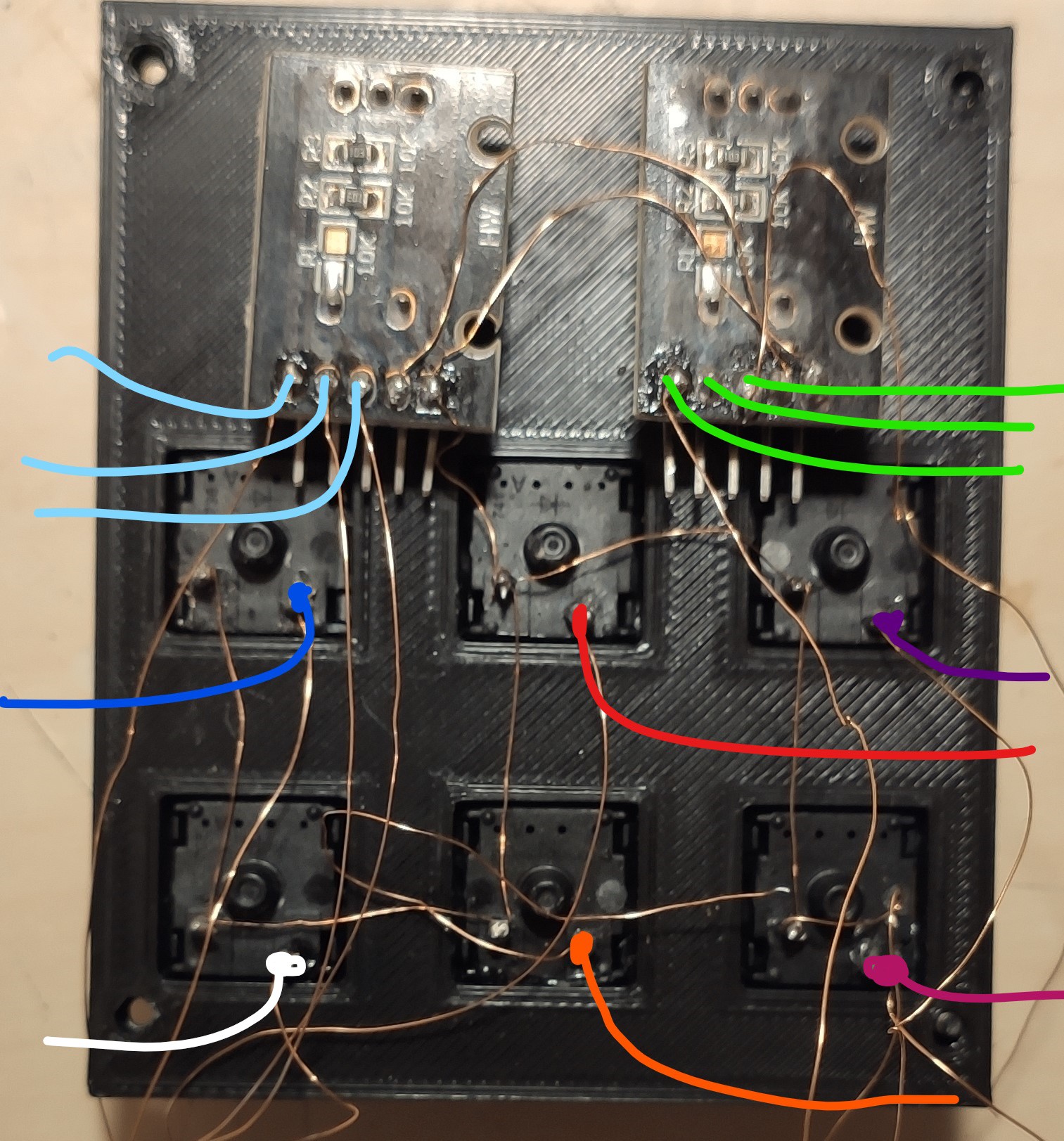
Solder a loose cable to all of the remaining pins of the switches and the encoders (colored cables).
![]()
-
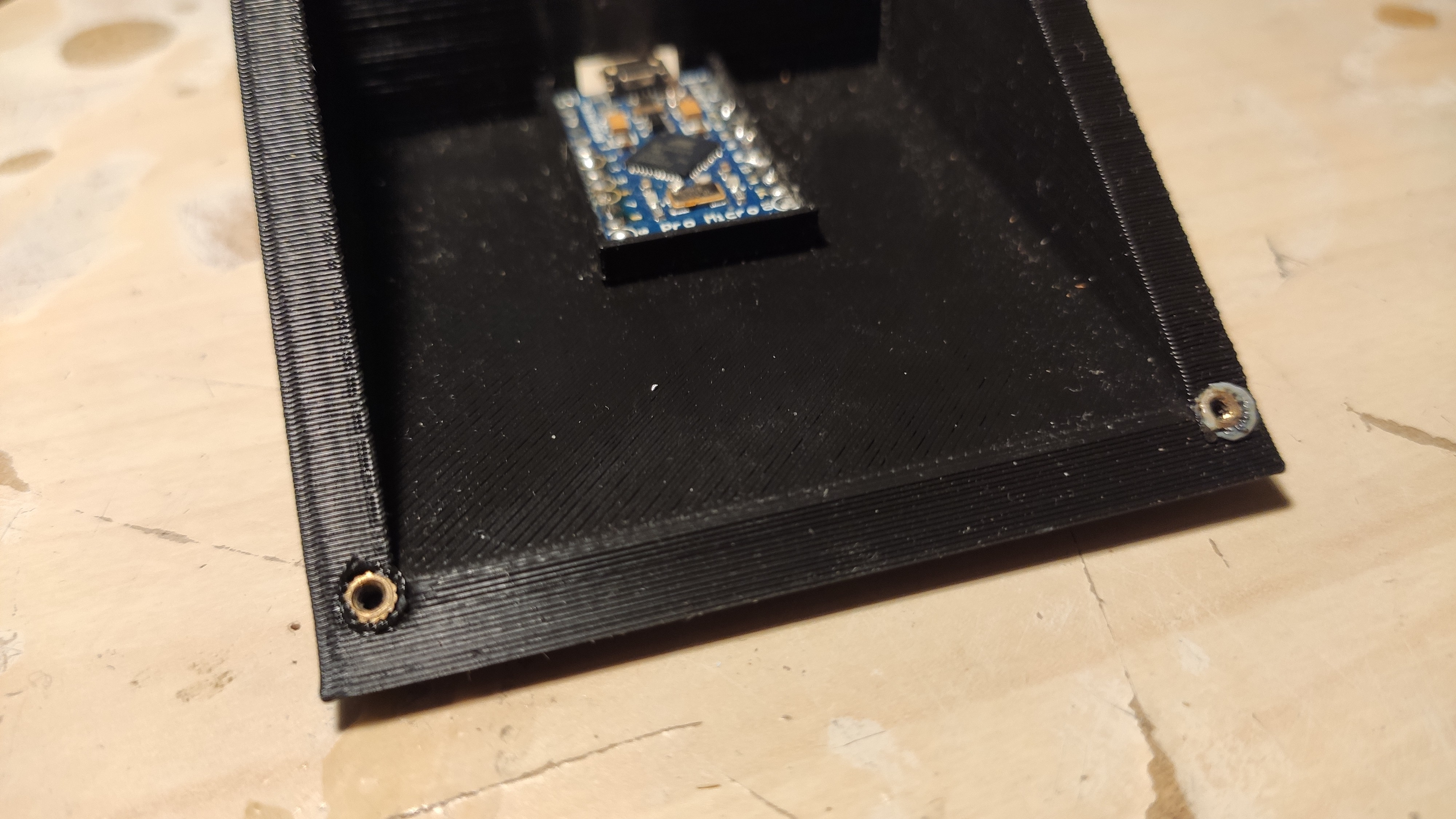
4Add the threaded inserts to the holes.
With a soldering iron melt the inserts in place.
![]()
-
5Solder loose cables to the Arduino
No special pins are required just solder the different cables to different pins of the Arduino, make sure to also solder the common ground and 5V from the encoders to the Arduino's ground and power pins.
For the example provided I wired the switches to pins 9, 5, 4, 8, 19 and 15. The "rotation" wires of the encoders are wired to pins 0 and 1 for one encoder and 2 and 3 for the other, and the clicking of the encoders is wired to pins 16 and 10.
-
6Place the Arduino on the 3D part
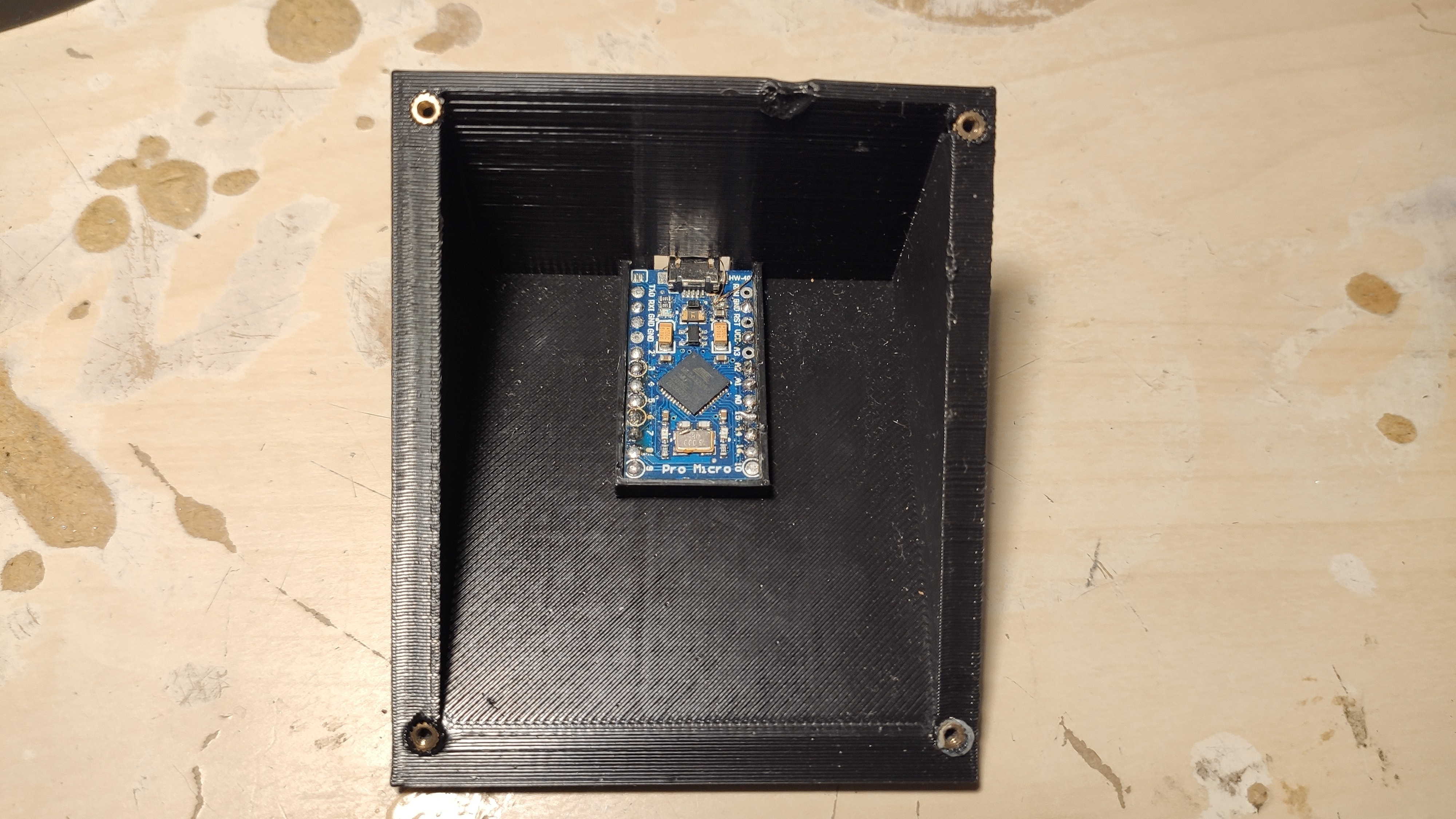
Click in place the arduino on the bottom part of the print.
![]()
-
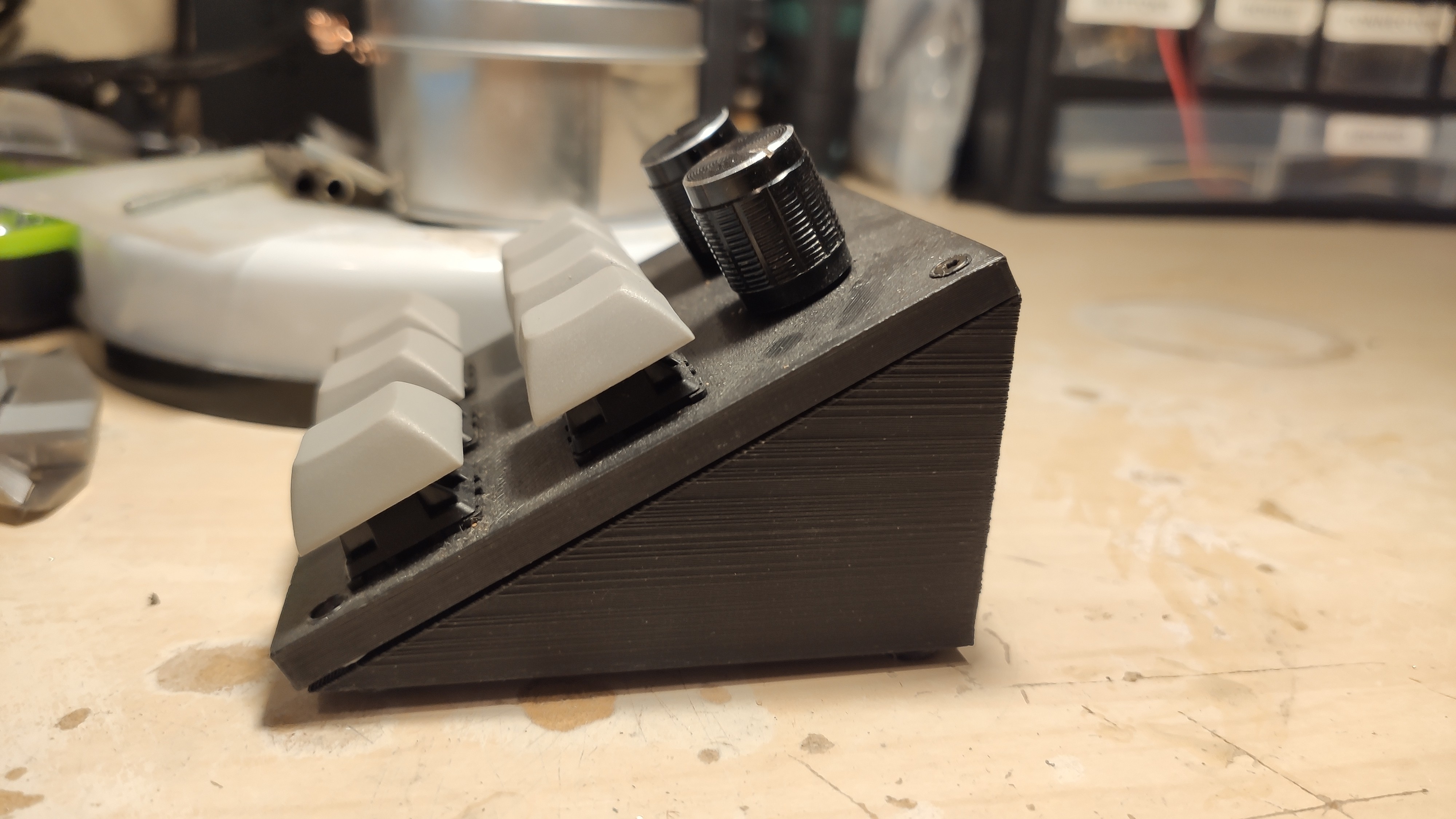
7Place the top part and screw in place
![]()
-
8Connect the Arduino via USB and flash the code
Flash the code provided and test that all the parts are working.
If all is well you can reprogram it to do whatever you want.
-
9(Optional) Add rubber feet
I glued some rounded silicon sheet on the four corners at the bottom to prevent it from sliding when I'm using it.
 NicLamrlr
Discussions
Become a Hackaday.io Member
Create an account to leave a comment. Already have an account? Log In.