Close
0%
0%

M.2 SATA to 44P IDE Adapter

A JM20330-based adapter to use M.2 SATA SSDs in place of 44-pin IDE DOMs and 2.5" drives.

Similar projects worth following
Many older thin clients and embedded devices use a non-standardized format of IDE flash storage known as a Disk On Module, or DOM. These often use the same interface as 2.5" IDE hard drives, but with a smaller footprint and slightly different connectors. Replacement modules are typically expensive and low capacity, and existing adapters that fit in a similar footprint use memory cards like SD or CF, which suffer from poor random access speed and questionable endurance.

This project aims to allow fast and relatively inexpensive SATA M.2 SSDs to be used in these older devices. With the correct connector, it should also work in place of 2.5" IDE drives.

(Note that this adapter is 44-pin IDE. It won't replace 40-pin DOMs or 3.5" drives, as those use a 2.54mm pitch and separate power connection.)

Bill of Materials

Reference(s) Qty Value Package
R1 1 470 0402
R2 1 37.4K / 1% 0402
R3, R4 2 12K / 1% 0402
R5, R7 2 100 0402
R6, R8, R10 3 10K 0402
R9 1 1M 0402
C1 1 47uF 1206
C2, C14, C16, C17 4 1uF 0402
C3, C18, C19 3 10uF 0603
C4, C5, C10, C11, C15, C20-C22 8 100nF 0402
C6-C9 4 10nF / 10% 0402
C12, C13 2 10pF 0402
D1 1 LED 0603
FB1, FB2 2 100-450 Ohms at 100mHz 0603
U1 1 JM20330 LQFP-64
U2 1 RT9059GQW DFN-10 EP
U3 1 MIC5305-1.8YML DFN-6 EP
Y1 1 25MHz +/- 50ppm 4 pin 2.0x1.6 mm
CN1 1 2mm pitch 2x22 header
CN2 1 TE 2199230-3 or 2199230-5 or 2199230-1

Notes/Alternatives:

Read more »

PATA to SATA IC Documents.zip

Various datasheets, schematics, and other documents I've collected regarding PATA to SATA bridge ICs.

x-zip-compressed - 46.64 MB - 03/04/2026 at 21:32

Download

IDE2SAT2.zip

PCB photos, measured component values, and reverse engineered schematic for Startech IDE2SAT2

x-zip-compressed - 16.86 MB - 03/04/2026 at 21:31

Download

SATA to IDE Rev 1.1 (with license).zip

PCB files and schematic. Rev 1.1 has some very minor changes from the prototype I tested, mostly with the silkscreen. (edit: Added license file)

x-zip-compressed - 1.20 MB - 10/12/2022 at 00:45

Download

JM20330 EVB-002-3.kicad_sch

Schematic of the official JMicron evaluation board

kicad_sch - 203.43 kB - 10/04/2022 at 00:44

Download

  • Marvell 88SA8052 Reverse Engineering

    loudaslife03/04/2026 at 21:23 0 comments

    Lately I've been working on a more universally applicable version of this project, with more form factors and configuration options. I have no idea when or if that will be finished, so in the meantime I'll share some of the background research I've done while working on it.

    One of the key features of the new version will be support for the Marvell 88SA8052 bridge IC as an alternative to the JMicron JM20330 in the existing design.

    If you've spent a lot of time in relatively obscure corners of internet forums where people discuss retro PC hardware, you might've seen discussions about which PATA to SATA adapter provides the best performance and/or compatibility. Very little exists in the way of objective testing, but anecdotal opinions overwhelmingly favor adapters using the Marvell 88SA8052, and in particular, Startech's IDE2SAT2 adapter. Since this adapter seems to be the internet's gold standard, I figured it was worth buying one and reverse engineering the design for use as a reference.

    My last PCB reverse engineering was done entirely with a regular camera, a flatbed scanner, and a plain soldering iron. I wanted to do a slightly better job this time, so this was the perfect excuse to build a motorized microscope that could capture high resolution images with glare removal and minimal perspective distortion. For the disassembly, I used a hot air station to remove all the SMD components without damaging their pads. Rather than sanding the solder mask off, I chemically stripped it away using a concentrated sodium hydroxide solution. (Don't try that at home unless you're qualified to handle hazardous corrosive chemicals.) Lastly, I sanded the outer copper layers off and photographed the inner ones through the thin layer of FR4 that remained.

    I'm not sure why the inner layers appear black when viewed through the fiberglass, maybe that's just the color of the adhesive that's used to bond the copper to the substrate. Anyway, I can't upload the 10+ GB of raw uncompressed images here, but I'll upload some reasonably high resolution ones on the project page for anyone that wants to examine this board in more detail, along with the measured component values and the schematic.

    There are a number of things about this design that either seem questionable or I just don't understand. Feel free to leave a comment if you think you can help explain them.

    1. Pull resistors R3 and R8 (on DMARQ and IORDY respectively) seem unnecessary and possibly detrimental. There are pull resistors of these exact values specified in the ATA-ATAPI spec, but they're meant to be on the host side, not the device side. These are also specified as minimum values. So, assuming these resistors are present on the host side (as required by spec), the duplicated resistors on the adapter will divide the effective resistance in half, bringing it well below the minimum.
    2. Pull resistor R11 (on INTRQ) is, like the above, specified only for the host. But to make things even more complicated, this one is specified to be either a 10k pull up or a 6.2k pull down ("depending upon the level sensed"), so 10k pull down isn't a valid configuration even for the host.
    3. I don't know what they were trying to accomplish with D1 at all.
    4. The analog ground design seems questionable in a lot of ways. It connects the two analog ground pins of the bridge IC, the crystal load capacitors, and the analog power decoupling capacitors. The PCB itself has no connection between analog and digital ground, so any current flow between the two grounds has to go through the IC. I'm not experienced enough to say with confidence that this is bad, but I'm definitely not going to replicate it myself.
    5. I've yet to find any documentation that explains why UAO would be connected to an LED. Maybe that pin has an alternate function as an activity indicator, and it's explained in the elusive 88SA8052 datasheet. Regardless, this is the only implementation I've seen with UAO or UAI connected to anything...
    Read more »

  • First Test Results

    loudaslife10/02/2022 at 00:15 0 comments

    After assembling revision 1.0 of my adapter, I tested it in a Wyse V10L thin client. Surprisingly, it worked perfectly on the first attempt. With a bit of tinkering on the host and drive settings, this was the performance I got:

    The Kingston SSD was a $12 ebay purchase, probably salvaged from a Chromebook. Because the drive speaks SATA to the JM20330, it shows up as a SATA device in most disk info utilities, even though the OS sees it as an IDE drive.

    For comparison, this is how the same SSD benchmarks in AHCI mode on a SATA III port in a modern system:

    Read more »

  • JM20330 Reverse Engineering

    loudaslife08/14/2022 at 01:40 0 comments

    The central component of this project is a PATA to SATA bridge IC. Unfortunately, there doesn't appear to be any suitable chip with (officially) publicly available documentation, so figuring out how to use them can be tricky.

    The most common IC for this purpose is the JMicron JM20330. It's been used in other open source hardware projects, and can be purchased in small quantities relatively easily (though you won't find it on DigiKey or other reputable distributors.) You can even find a leaked old revision of its datasheet with some googling. However, the datasheet only gives limited information on the supporting components required. To fill in the gaps, I purchased what appears to be the official product evaluation board, the JM20330 EVB-002-3 "Host Bribge" Adapter.

    Read more »

View all 3 project logs

Enjoy this project?

Share

Discussions

Victor Hugo wrote 10/05/2024 at 01:01 point

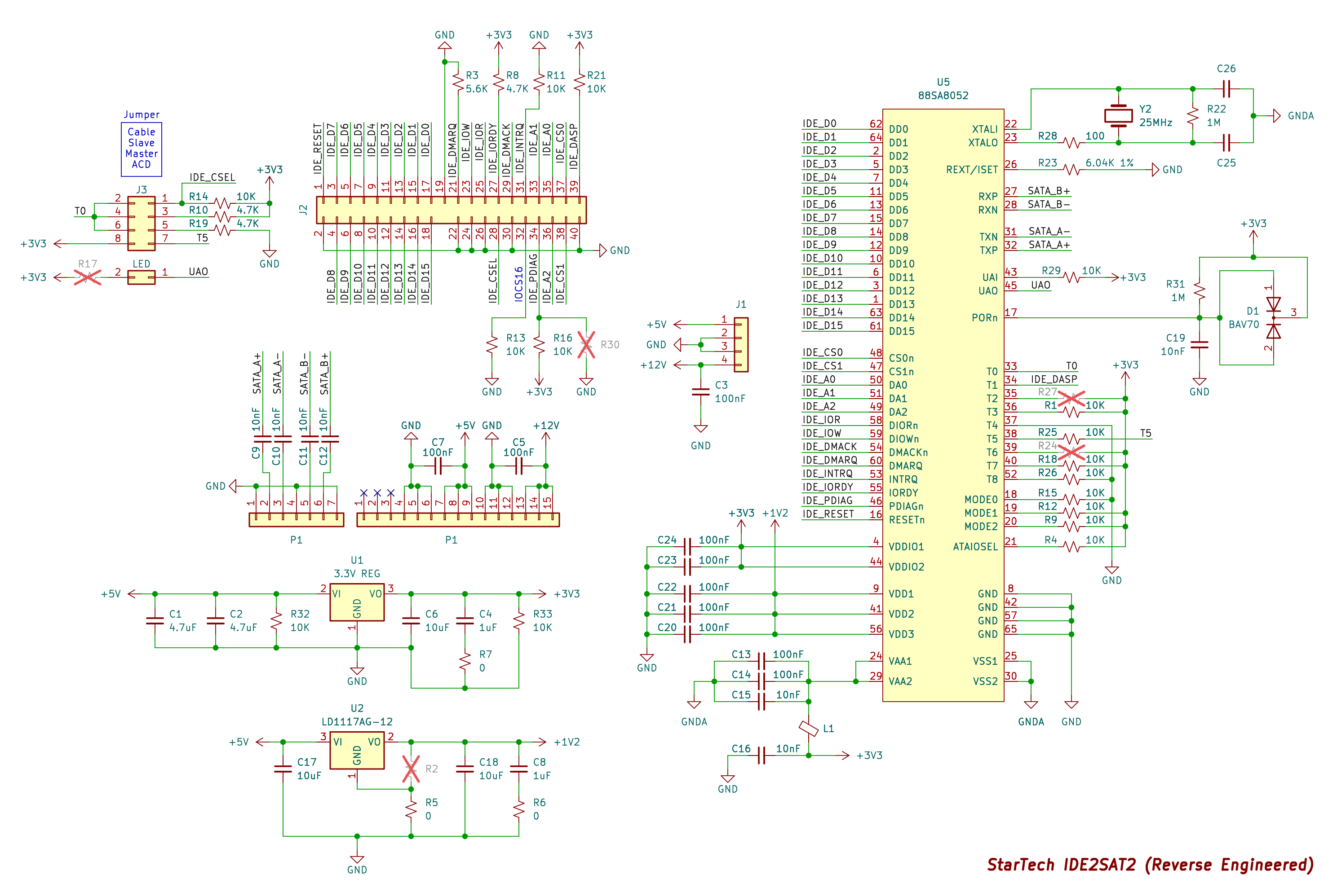
Hello, thank you very much, I'm designing a PCB (I'm a beginner) for the PS2 slim HD mod, and your schematics were essential for me to do it. 
I have just one question though, on the schematics the operating speed is determined by MODE 1 and MODE 0, but the settings are ignored if FXDMA is connected to ground, but in that case what speed does it operate? 

  Are you sure? yes | no

spotopolis wrote 03/14/2023 at 15:44 point

Im a total novice when it comes to PCB designs. How difficult would this be to adapt this project to fit the 40pin IDE connector and add a JST PHD (model S12B-PHDSS) header for power? This could be a perfect solution to a project I am working on rather than trying to develop my own custom IDE to SATA adapter where the IDE connector is extended by 1.25in and at a right angle and uses the JST header. This project would allow for a much smaller footprint.

  Are you sure? yes | no

PanciO wrote 02/14/2023 at 06:37 point

Hi, It's very interesting project... I'll  try to use it to connect Retro 8-bit computer to SATA drive :-)

Thanks!

  Are you sure? yes | no

powiadam.ci wrote 10/04/2022 at 21:01 point

Please add replacement firmware to your project

for example some people need hardweare encrypt whole disc or compressing

  Are you sure? yes | no

loudaslife wrote 10/04/2022 at 21:14 point

I'm not sure what you mean. The JM20330 doesn't have any firmware, as far as I know.

  Are you sure? yes | no

powiadam.ci wrote 10/05/2022 at 09:09 point

So far it doesn't, but it may have.
I gave an example of application. Disk hardware encryption. Adding this functionality is not difficult I think.

  Are you sure? yes | no

Corscaria wrote 04/01/2023 at 14:18 point

SATA bridge chips are not programmable, they perform a single function translating SATA to PATA and back. If you want encryption you are going to have to implement it in software.

  Are you sure? yes | no

Similar Projects

Does this project spark your interest?

Become a member to follow this project and never miss any updates