loudaslife
-
First Test Results
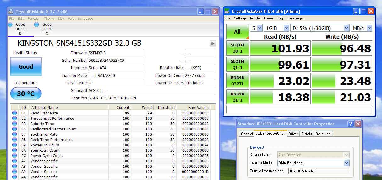
10/02/2022 at 00:15 • 0 commentsAfter assembling revision 1.0 of my adapter, I tested it in a Wyse V10L thin client. Surprisingly, it worked perfectly on the first attempt. With a bit of tinkering on the host and drive settings, this was the performance I got:
![]()
The Kingston SSD was a $12 ebay purchase, probably salvaged from a Chromebook. Because the drive speaks SATA to the JM20330, it shows up as a SATA device in most disk info utilities, even though the OS sees it as an IDE drive.
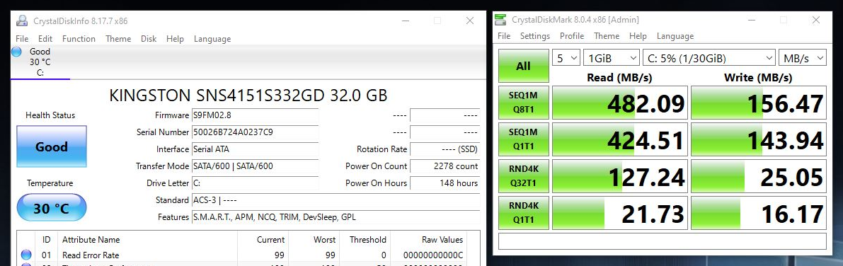
For comparison, this is how the same SSD benchmarks in AHCI mode on a SATA III port in a modern system:
---------- more ----------![]()
The adapter is clearly much slower in some metrics, but interestingly, it performed 30% better on 4K Q1T1 Write. I don't know enough about flash storage or interfaces to even guess why. I will, however, speculate that the large performance difference on 4K Q32T1 Read is probably due to Native Command Queueing, which isn't supported in IDE mode.
The roughly 100 MB/s bottleneck in sequential access could easily be due to the VIA chipset in this host, so I'm not yet sure where the limit of the JM20330 lies. In the future, I plan to test other M.2 drives and hosts to figure this out.
Even though I think this can go faster, it already equals or exceeds any other practical IDE storage solution I've seen, so I'm pretty happy with the results. If anyone out there finds better benchmark results using the JM20330 (or any SATA/IDE bridge) please share them!
-
JM20330 Reverse Engineering
08/14/2022 at 01:40 • 0 commentsThe central component of this project is a PATA to SATA bridge IC. Unfortunately, there doesn't appear to be any suitable chip with (officially) publicly available documentation, so figuring out how to use them can be tricky.
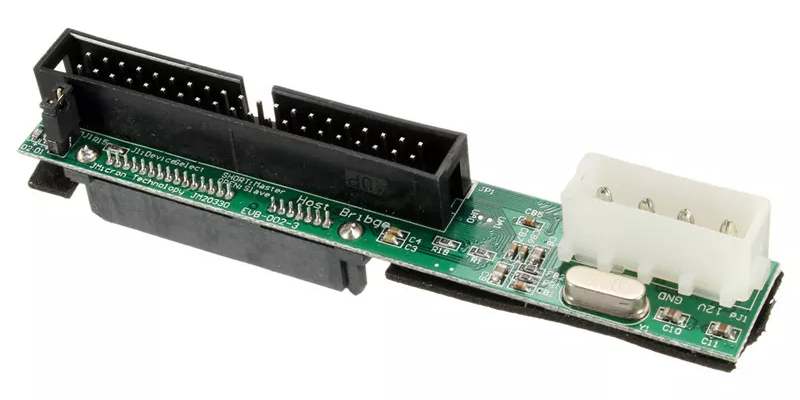
The most common IC for this purpose is the JMicron JM20330. It's been used in other open source hardware projects, and can be purchased in small quantities relatively easily (though you won't find it on DigiKey or other reputable distributors.) You can even find a leaked old revision of its datasheet with some googling. However, the datasheet only gives limited information on the supporting components required. To fill in the gaps, I purchased what appears to be the official product evaluation board, the JM20330 EVB-002-3 "Host Bribge" Adapter.
![]() ---------- more ----------
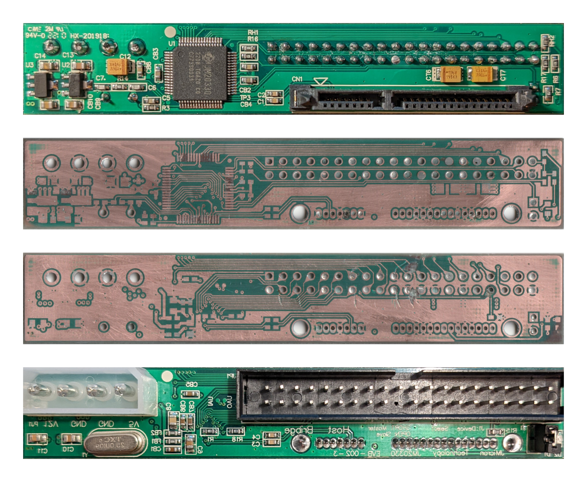
---------- more ----------Considering their secrecy with datasheets, I don't think these are something JMicron authorized to be sold to the public. Rather, I suspect an unscrupulous manufacturer acquired the design files or manually recreated them (misspelling "Bridge" in the process). Regardless, this seemed like the closest thing to an official reference implementation that I could get. After a very barbaric dissection, I had decent pictures of the PCB traces and a spreadsheet of component values measured with my $15 "LCR-T4" component tester. Note that the lower photos are mirrored. I didn't photograph the inner layers, but they only seem to carry power and ground.
![]()
It was immediately apparent that many of the component values used in this sample probably weren't faithful to the original design. Some were replaced with cheaper ones, like 0 ohm links instead of ferrite beads. Others just didn't make sense, like having both 10uF tantalum and 10uF ceramic caps.
While I was researching this, I managed to acquire a copy of the official JMicron schematic for this board. It confirmed my suspicions, but also made all of my work so far pointless. Oh well.
Reference designator(s) As purchased from AliExpress Official schematic value C1-C4 10nF 10nF C5 100nF 1uF C6 (too low for my tester to measure) 5pF C7 (too low for my tester to measure) 33pF C8-C11, C13-C14 10uF 10uF/10V C12, CT6-CT7 10uF tantalum 22uF/16V tantalum CB1-CB8 100nF 100nF CB9-CB10 10uF 100nF FB1-FB2 0 ohm link 100-450 ohm at 100MHz R1 10K 12K 1% R3 10K 47K R6 300 330 R7 1K 1K R14 10M 1M R15 10K NC or 0 R16 10K 100 or NC R17 300 100 R18 10K 1K RH1 0 ohm link 10K RH2 10K 10K Y1 25MHz 25MHz U1 JM20330 JM20330 U2 6206A SHC/1.8 APL5508-1V8 U3 6206A H221HD/33 APL5508-3V3 D1-D2 LED LED I forgot to test the knockoff board before tearing it apart, so there's no guarantee that the values it used actually work. Other than the values, though, my reverse-engineered schematic matched the official one exactly, so the PCB itself appears to be a faithful duplicate. I updated my schematic with the values used in the official one, and I've added the .kicad_sch file to the project files for whoever wants it. I used a schematic from the S6SSD project as a starting point and general reference, so credit to Wenting Zhang.
![]()
M.2 SATA to 44P IDE Adapter
A JM20330-based adapter to use M.2 SATA SSDs in place of 44-pin IDE DOMs and 2.5" drives.