 Pierluigi Zagaria
-
1Setting up ESP-ADF framework
Pain.
This is all I felt by configuring and getting the board working with the framework.
Unfortunately this board is a mess.
The elettronic schemes found on the internet are wrong and in newer version they changed the audio codec to an es8388.The best way to get this working is to look at issues and pulls request to esp-adf, arduino-audiokit and the official repo of the board.
After a while, I got the voip example from esp-adf working!
I could listen to sound by connecting headphones to the output and pick up sound from the headphone speaker (yes the headphone speaker were acting as microphone and not the microphone per se) if connected to the line input. -
2Setting up a PBX server
To configure a VOIP server on my raspberry I almost cried.
Tried any docker PBX image, some worked but the networking was completely broke, some were so outdated and at some point I even installed FusionPBX that broke my entire raspberry configuration so I had to format and reinstall everything again (from now on I got backups).But then I found miniSIPServer.
if i was going to cry for the previous misadventures, this time I wanted to cry with joy at how easy it was to set up and start a VOIP PBX server with just 1 command.
The only issue is that the software is not open source and you must pay a licence to use more than 5 clients.but, who cares?
The final result is what matter the most!
-
3Piping audio to the board
This was pretty straightforward.
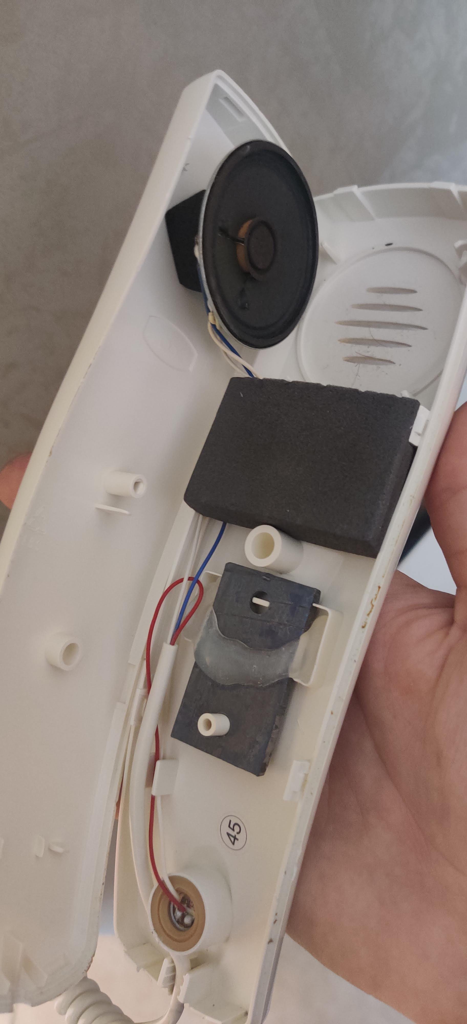
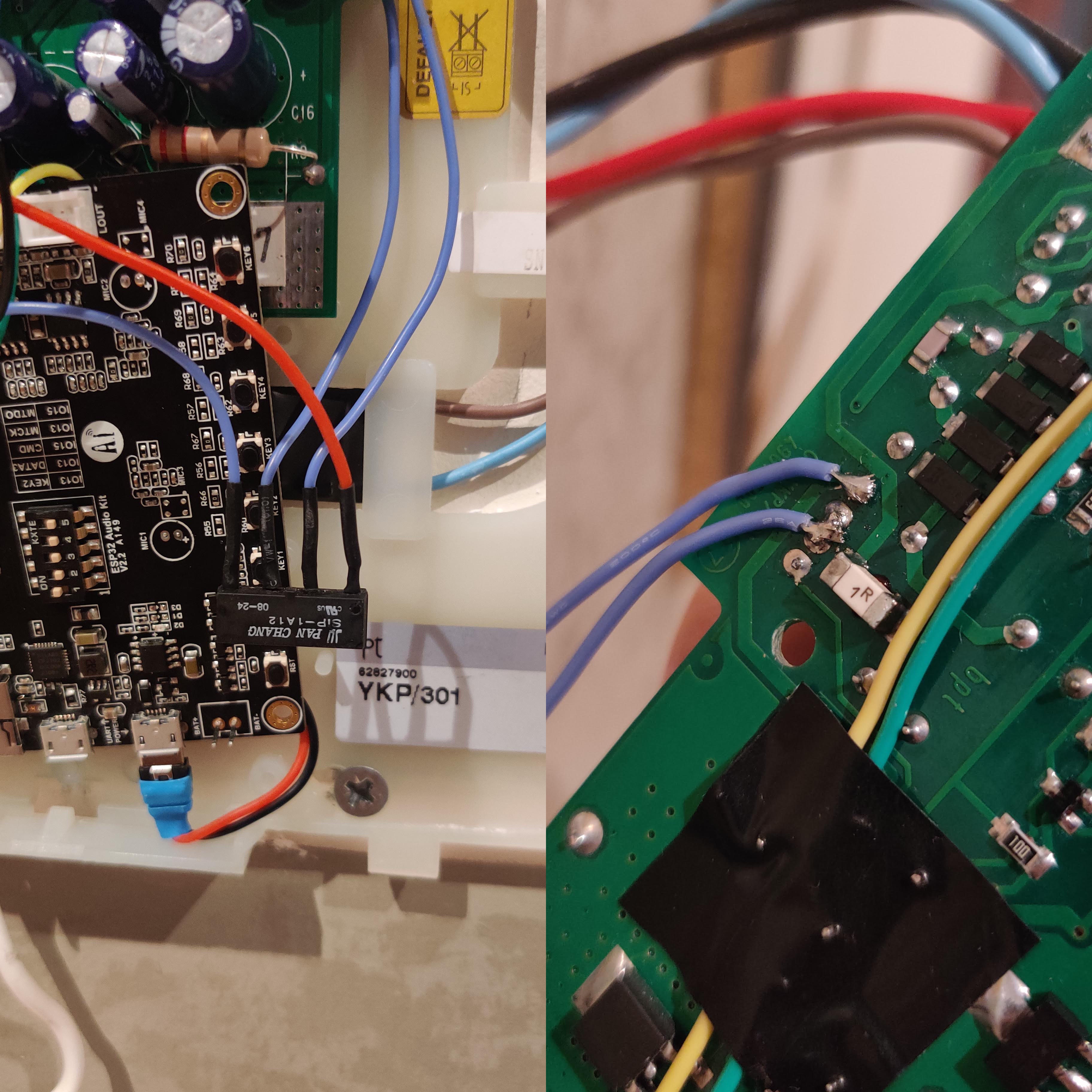
After dissasembling the intercom I discovered that the handphone is connected with 3 wires.
White is shared between speaker and microphone (ground), blue goes to speaker and red goes to microphone.![]()
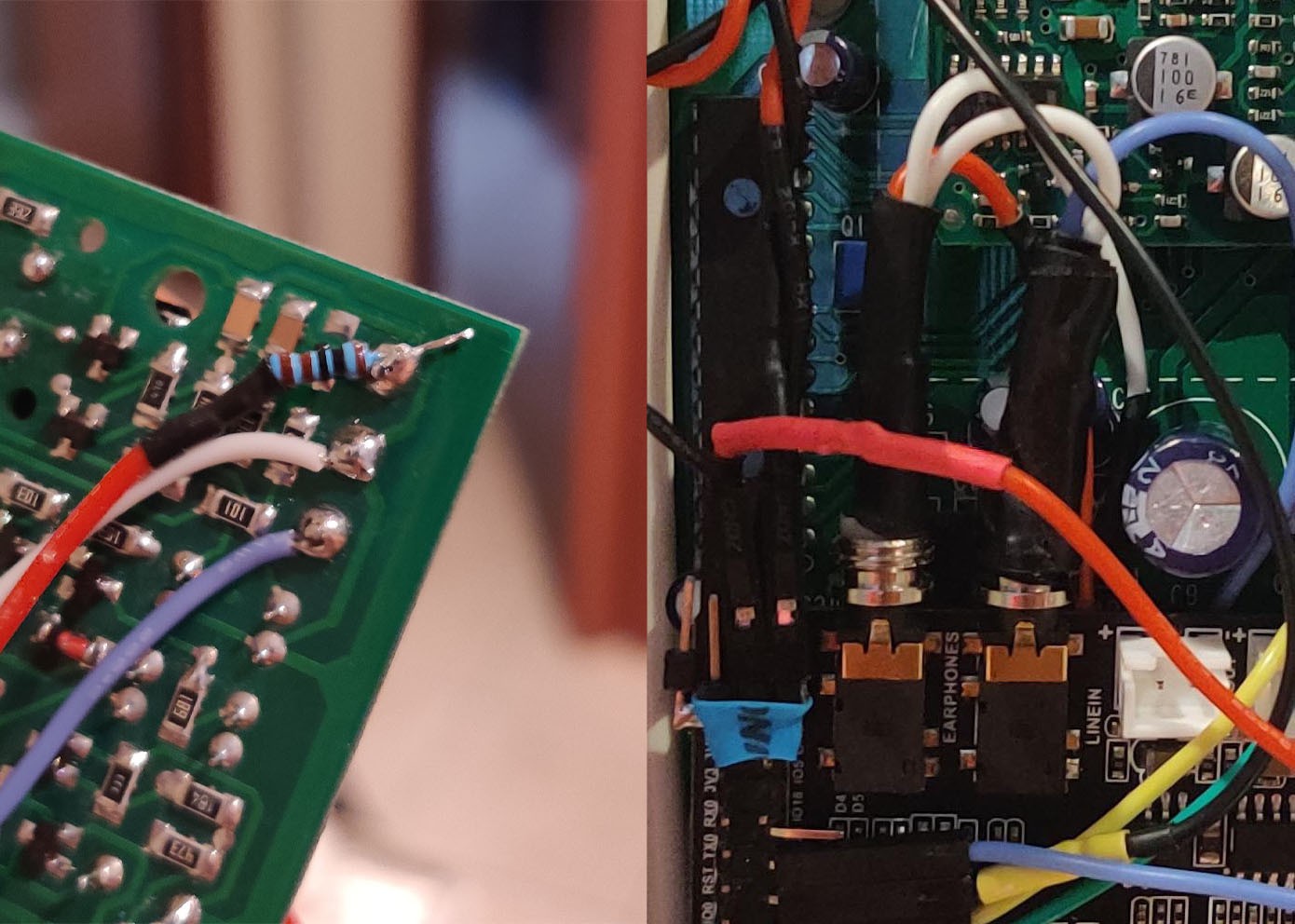
The idea is very simple, to inject audio into the intercom I should connect the audio board output to the handset input (red wire) and handset speaker (blue wire ) to the audio board input.
![]()
The audio driver tries to keep the output quiet so it actively drives the microphone signal to ground. This prevented the handset microphone to work properly. To fix that I've used a 1K ohm resistor before connecting the board ouput to intercom handset microphone. (Big thanks to netl for the suggestion!)
After properly soldering the wires to the two jacks I can now call the board with my phone and hear sound from the outsite!
-
4Power the board and control the intercom
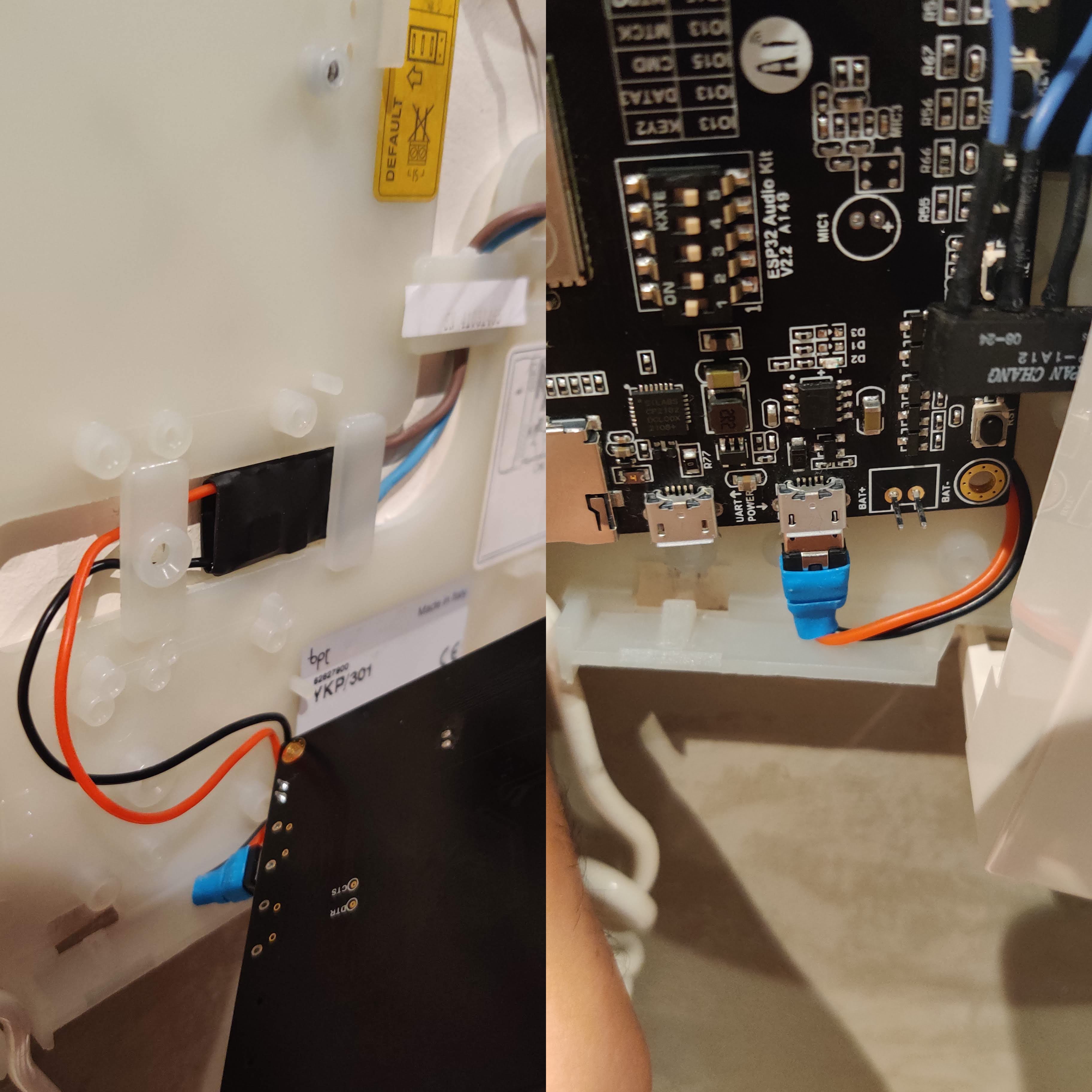
The board is powered using a buck step-down converter (MP1584EN) that takes the 12v from the intercom and converts it to 5v. I didn't want to solder wires directly for debugging purposes. So I took a micro-usb cable and removed all the useless plastic that took space.
![]()
To open the front door I have to press a button. With the condition that the monitor must be ON.
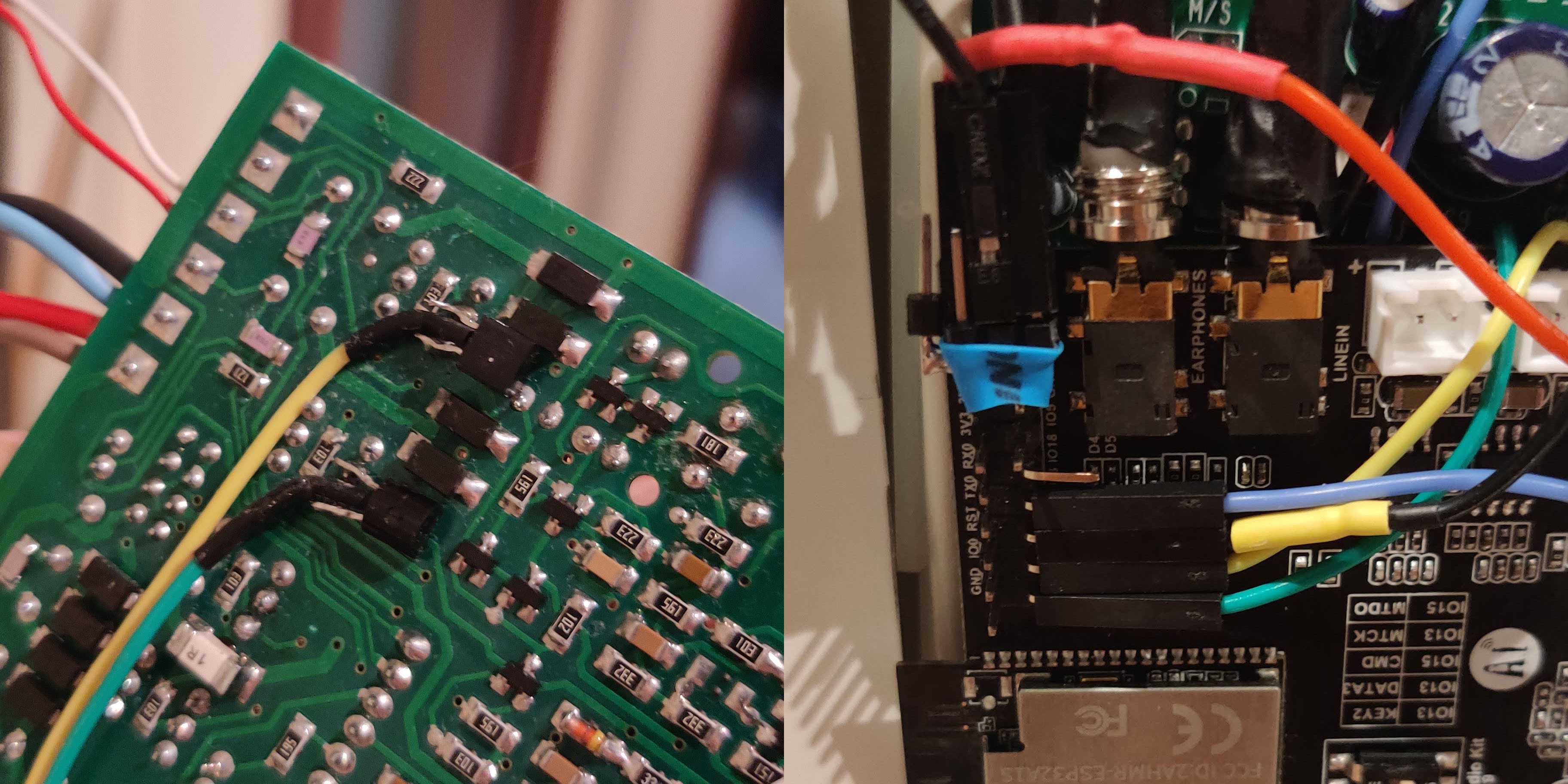
In order to control them I used BC547 NPN transistor to short circuit the two needed buttons (door and monitor). The transistors bases are saturated by a 1K ohm resistor and controlled by 2 GPIO pins of the board. This allows the current to flow from collector to emmiter short circuiting the buttons. I think this is possible thanks to the buck step-down converter that lets the board share the same ground with the intercom.![]()
-
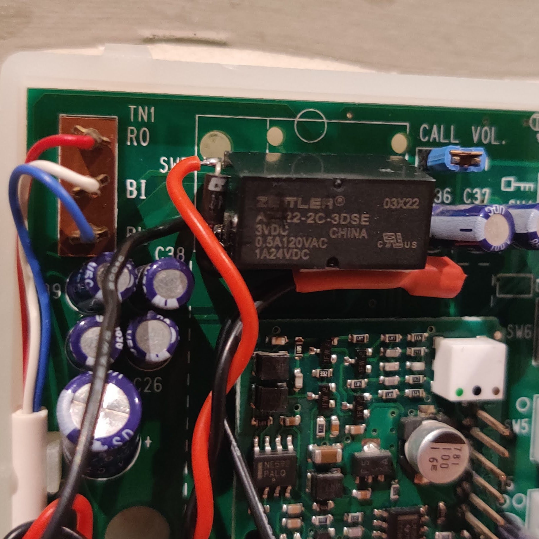
5Detect when the intercom RIIINGS
This is probably the worst part of my project so I'm aware of that.
Another challenge for me was to detect when the intercom was ringing. Reverse engineering was not an option for me for my poor knoledge in elettronics. When someone rings, the intercom monitor turns on. I soldered a simple relay to the 12v power wires of the monitor. In this way when the it turns on, the relay is switched and let current flow to a GPIO input interrupt. It works but a voltage divider could have been a better choice.
![]()
Here is a snippet for such an interrupt
#define GPIO_MONITOR_SENSOR GPIO_NUM_23 ... static bool is_monitor_on; ... static void gpio_task(void *arg) { uint32_t io_num; for (;;) { if (xQueueReceive(gpio_evt_queue, &io_num, portMAX_DELAY)) { if ((io_num == GPIO_MONITOR_SENSOR) && is_monitor_on != gpio_get_level(io_num)) { sip_state_t sip_state = esp_sip_get_state(sip); is_monitor_on = gpio_get_level(io_num); ESP_LOGI(TAG, "GPIO[%d] intr, val: %d, is_monitor_on %d", io_num, gpio_get_level(io_num), is_monitor_on); if (is_monitor_on && (sip_state & SIP_STATE_REGISTERED)) { esp_sip_uac_invite(sip, SIP_CALL_NUMBER); } else if (!is_monitor_on && (sip_state & SIP_STATE_ON_CALL)) { esp_sip_uac_bye(sip); } else if (!is_monitor_on && ((sip_state & SIP_STATE_CALLING) || (sip_state & SIP_STATE_SESS_PROGRESS))) { esp_sip_uac_cancel(sip); } } } } } void setup_gpio() { gpio_pad_select_gpio(GPIO_MONITOR_SENSOR); gpio_set_direction(GPIO_MONITOR_SENSOR, GPIO_MODE_INPUT); gpio_pulldown_en(GPIO_MONITOR_SENSOR); gpio_set_intr_type(GPIO_MONITOR_SENSOR, GPIO_INTR_ANYEDGE); gpio_isr_handler_add(GPIO_MONITOR_SENSOR, gpio_isr_handler, (void *)GPIO_MONITOR_SENSOR); } ... void app_main() { ... ESP_LOGI(TAG, "[ 4 ] Setting up GPIO pins"); setup_gpio(); } -
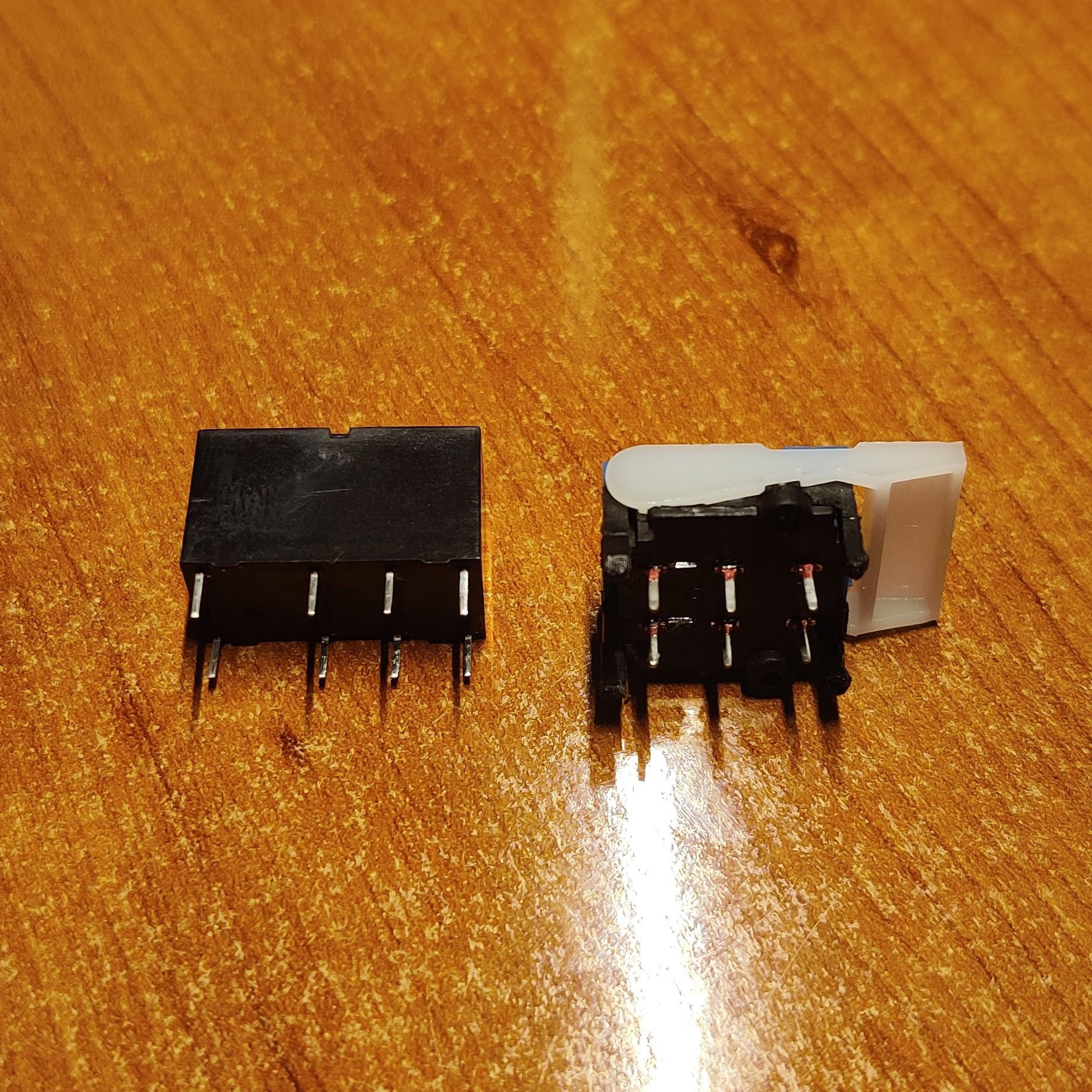
6Replace the hook switch
In order to open or close a call, every intercom detects if the handset is being picked up or not. To do that a hook switch is commonly used. It is a simple spring loaded switch that opens up when the handset is picked up. In my case it was a 6 pin DPDT switch.
![]()
I'm not an elettronic engineer and I didn't want to reverse engineer the PCB to answer the call and let the audio into the handset/audio board. I decided to replace it with a DPDT relay that could be controlled by the board. To control it I used the BC547 NPN transistor and a fallback diode to protect the circuit. The base is satured with a 1K Ohm resistor. In this way I can answer and close the calls by using a simple GPIO output pin!
![]()
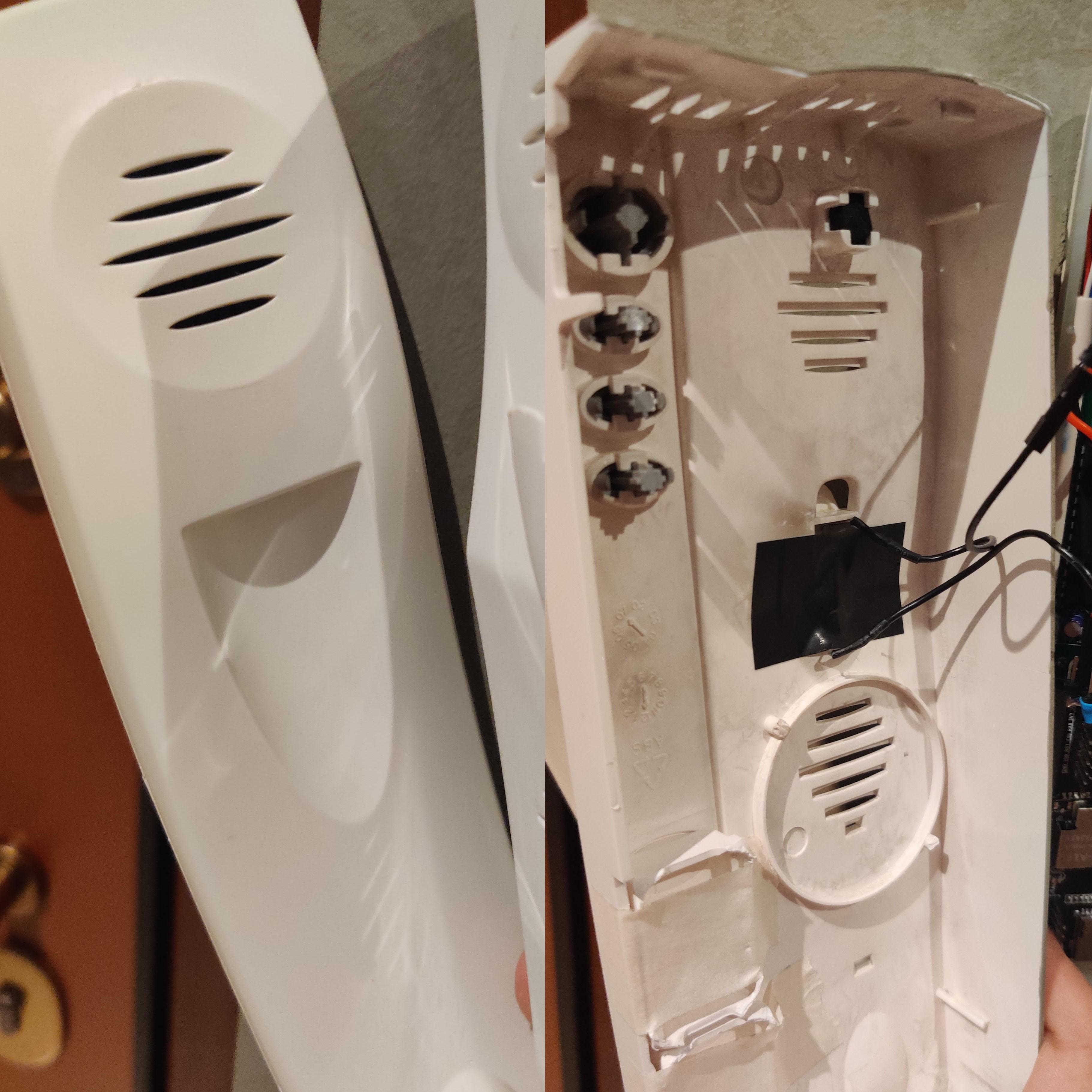
BUT! A new problem pops out...
Now that I've replaced the hook switch I can't detect if the handset is picked up or not. So the intercom functionality is compromised. After thinking for a while a simple and easy idea come to my mind: MAGNETS. I can use a NO (normaly open) reed switch and put a magnet inside the handset. When it gets picked up the switch is closed and short circuits the relay directly to the GND of the board without passing through the transistor.
AWESOME!
![]()
HOW I HACKED MY INTERCOM SO I CAN BE MORE LAZY
Answer intercom and open the door with phone
Discussions
Become a Hackaday.io Member
Create an account to leave a comment. Already have an account? Log In.