Nikola Manolov
-
Exiting news and a cool experiment.
10/06/2022 at 08:57 • 0 commentsFirst of all the exciting news.
I'm extremely happy to announce that I have started a CrowdSupply campaign in order to get the USB Power Injector to people who would find it useful. If you are interested feel free to check it out at CrowdSupply. Now to the experiment
Fast dynamic current measurements

For some measurements using just an amp meter to capture current draw may be insufficient. Let’s say we are trying to capture the maximum current drawn by a Wi-Fi module while it’s making a HTTP request. Let us explore this exact task using a module with ESP8266 Wi-Fi enabled microcontroller, Micsig CP2100B current probe and a scope.
The module is programmed to make an HTTP request every second.
Capture 1 at 100uS / division Capture 2 at 100uS / division Capture 3 at 500mS / division. As we can clearly see, capturing the maximum current draw is trivial. As well as capturing how often and for how long the transmitter is turned on. This could be of great help when developing battery powered devices, where minimizing the power draw is paramount. Since the USB Power Injector uses standard 4mm banana plugs, it would be equally easy to use a different kind of current probe. For example it would easily interface with popular uCurrent Gold developed by Dave Jones.
-
Testing a product’s voltage range
10/01/2022 at 20:00 • 0 commentsAccording to the USB 2.0 standard, the USB Vbus voltage can range from 4.4V to 5.5V. A USB Device needs to be able to work in at least that range and probably lower due to the voltage drop in the cables. With the USB Power Injector, that test is trivial.
For this test I have selected three devices:
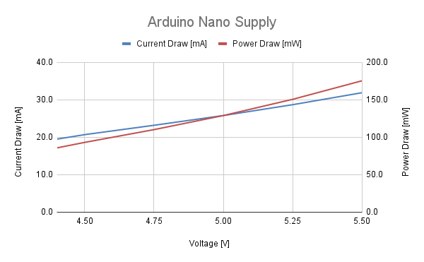
- The Arduino Nano. On it the VBus is connected directly to the Atmega328.
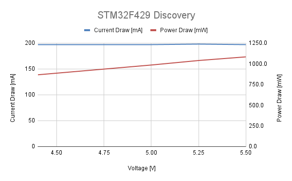
- STM32F429 Discovery Development Kit. On it VBus goes trough a 3.3V low drop linear regulator before going to the STM microcontroller.
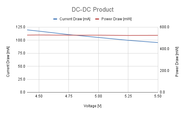
- A USB powered single board computer I developed for work. Unfortunately, I can't go in to details on it, but it uses DC-DC convertors that drive the main processor.
The Arduino and the single board computer will be idling in an infinite loop. The STM Discovery will be running the default demo application.
All three board will be tested at different voltages in order to determine if they are function correctly. While I’m at it, I’m going to measure the current consumption of each device at each voltage in order to compare each power supply scheme characteristics.
Current Draw Table All three devices worked in the voltage range from 4.4 to 5.5V. As is usual for boards powered by linear regulators, the supply current for the STM discovery stays more or less constant, regardless of the voltage. Likewise, the DC-DC convertor powered single board computer keeps the power draw constant, regardless of the supply voltage. Since the Atmega328a was not powered by a constant voltage, its current and power draw had a clear rising trend, if we increased the voltage. Knowing the behaviour of common power supply schemes can help us track problems in products we are developing, if we are not observing them due to a failure in a component or an error in the design.
-
Basic usage and slow dynamic current measurement.
09/23/2022 at 11:42 • 0 commentsExperiment Block Diagram In the first test we are going to explore a basic use case for the USB Power Injector. As shown in the video, we have an Arduino Nano connected to a PC running the Arduino IDE. At the same time, the Nano is powered by a benchtop PSU and we can set its supply voltage and a protective current limit. This setup allows for full control of the Arduino, both in terms of how we power it and how we communicate with it. A new firmware can be uploaded, as shown in the video (I change the blink time). It also allows for communication via the virtual COM port.
This setup also allows for some slow dynamic power measurements. A milliamp meter is connected in series with the Arduino, in order to measure the supply current more accurately. When the Arduino LED is off, the board draws 27.2mA and when it’s on it drawn 32.5mA. This functionality can be quite useful to roughly determine what state a board is. For example, if a wireless transmitter is off, the product under test will draw less current. For general purpose development work I usually skip the amp meter and just use the amp meter embedded in the power supply.
USB Power Injector
USB Power Injector allows for a way to power up USB 2.0 devices from a lab power supply, while allowing data transfer from host to device.