Michael Gardi
-
My Second Skin Gets a Skin
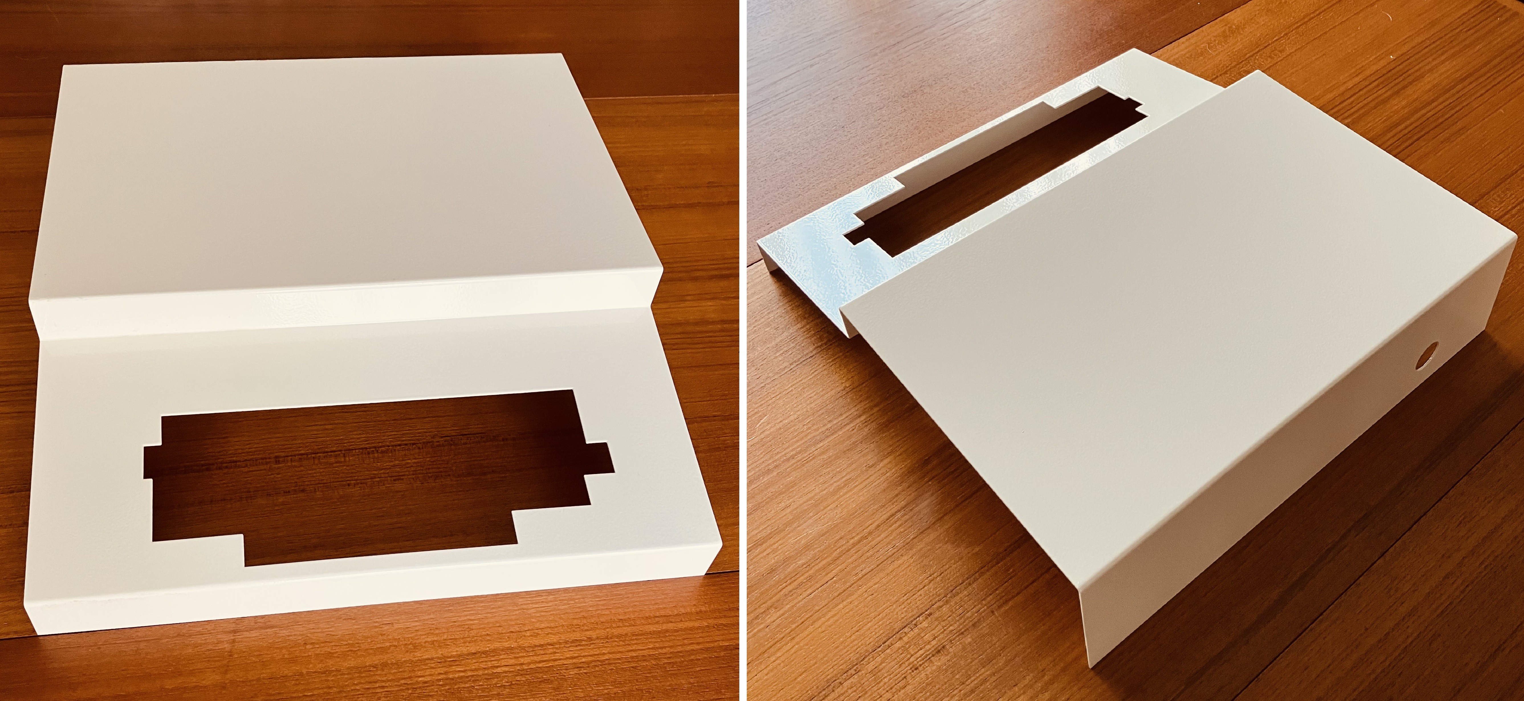
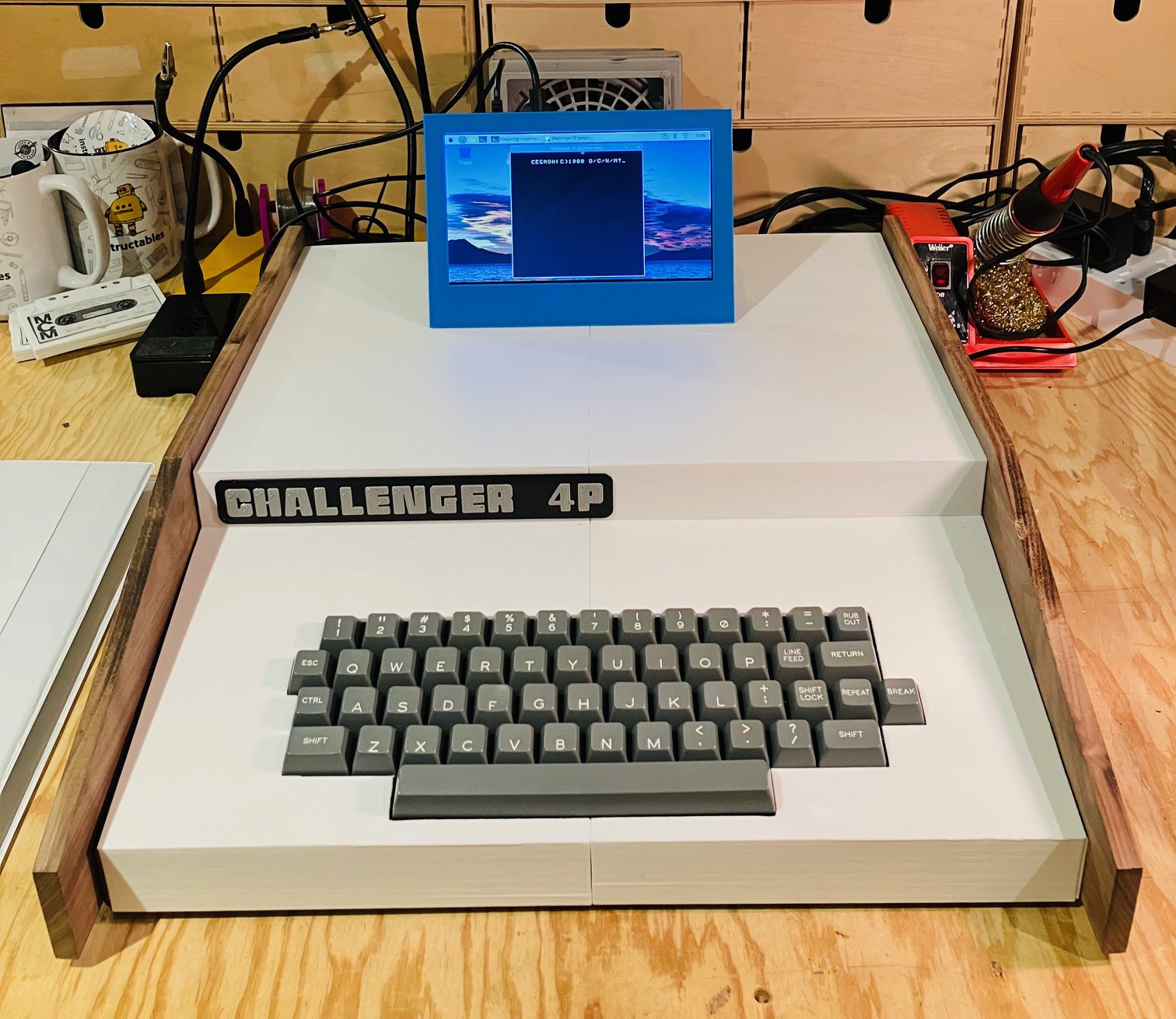
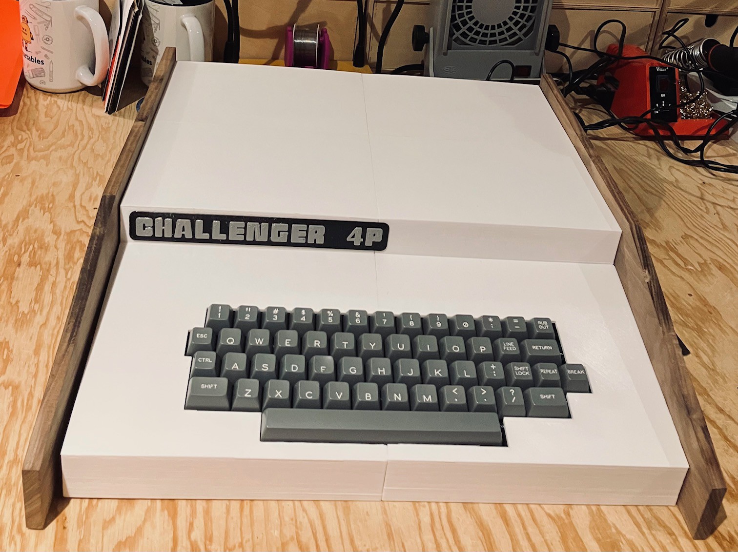
05/05/2023 at 19:46 • 2 commentsI decided to have the cover for my Challenger 4P which was fabricated at LASERBOOST (see Getting a Second Skin and Metal Magic) powder coated at a local shop (Westex Coatings Inc.). I just got the piece back today and I'm very happy with the result.
![]()
With the proliferation of 3D printers, the 3D printed "skins" I have designed for this and my other reproductions, are easily within the reach of a large number of makers. Now, companies like LASERBOOST are making sheet metal fabrication more accessible as well. Even though my reproductions for the most part have emulated "insides", I have always strived to make the exteriors match as close to the original's as possible. My new sheet metal skin goes a long way towards achieving that authenticity for the Challenger 4P.
-
Metal Magic
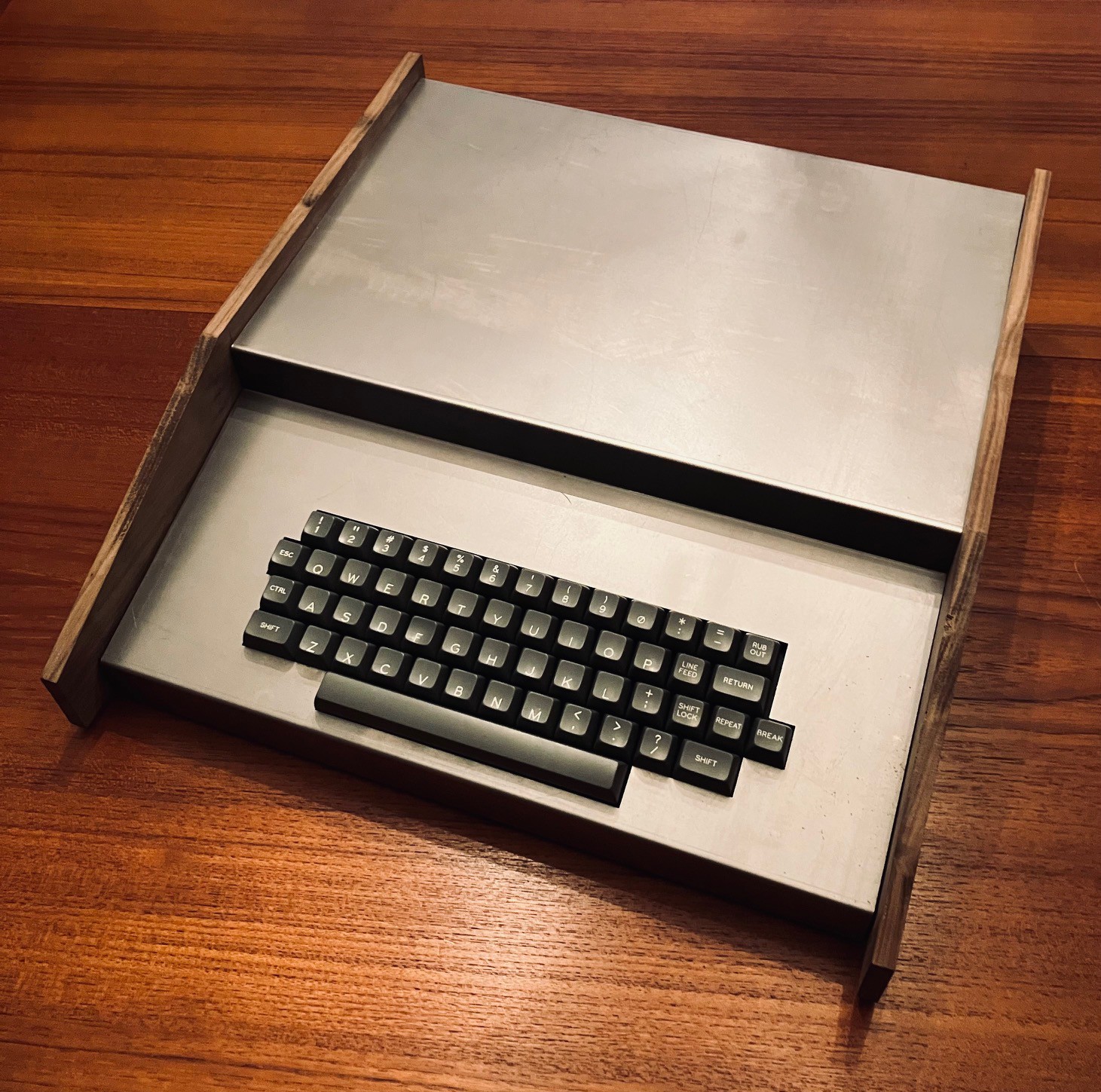
03/27/2023 at 00:11 • 0 commentsThe fabricated steel top for the Challenger 4P arrived today from LASERBOOST (see Getting a Second Skin). Wow. What an incredible job they did.
![]()
A perfect fit! So happy. Now I have to figure out what kind of finish to apply to it.
-
The Need for Speed
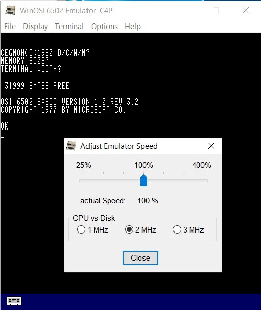
03/21/2023 at 17:43 • 0 commentsMarch 22, 2023 Correction: I changed the relative speeds that my emulator runs at because I learned that WinOSI running at 100% is actually 1 MHz not 2 MHz. The CPU vs Disk setting does not factor in.
April 2, 2023 Update: Using Python3.11 and pypy broke access to the GPIO pins necessary to support the hardware keyboard. I ended up switching from the RPi.GPIO library to using pigpio which was easier to install into these new Python environment.
Throughout the build I had the nagging feeling that my emulator was a little sluggish performance wise, but there were so many other things to do I never followed up. Well now that the project was nearing completion it was time to look into this.
I don't have a real Challenger 4P to compare with so how could I determine if my emulator was running slowly? Well I do have another emulator to compare with, WinOSI. One has to assume from the Adjust Emulator Speed dialog seen below, that the author took a lot of care getting the speed that the emulator runs at to be accurate.
![]()
So I wrote a small BASIC program.
10 I = 0
20 Print I
30 I = I + 1
40 IF I = 1000 GOTO 60
50 GOTO 20
60 END
Setting WinOSI to run at 1 MHz as shown above I ran this program and timed how long it took to finish. Then I ran the same program on my emulator. The results confirmed that my emulator wasn't quite in up to snuff.
Emulator       Runtime Environment       Time To Run
~~~~~~~~       ~~~~~~~~~~~~~~~~~~~       ~~~~~~~~~~~
 WinOSI     Windows 10/C++ Executable       1:02
 Project    Raspberry Pi OS/Python 3.9      2:04
In fact it was running at half the speed, about .5 MHz. Yikes!
So what to do. Hitting google, "Speeding up Python" offered a number of suggestions. Many of the suggestion involved making changes to the code to use more efficient Python constructs. OK good to know. I also found out that the folks at python.org had recently issued a new release, Python 3.11, with some good performance enhancements. So I tried that and had some success.
Emulator       Runtime Environment       Time To Run
~~~~~~~~       ~~~~~~~~~~~~~~~~~~~       ~~~~~~~~~~~
 WinOSI     Windows 10/C++ Executable       1:02
 Project    Raspberry Pi OS/Python 3.11     1:13
That gets me to about .85 MHz. I could almost live with that but I also wanted to try PyPy, an alternative implementation of Python. Pypy has a Just In Time (JIT) compiler that will optimize heavily used parts of your Python code by converting those parts to native code. I suspected that the JIT would be a good fit for the 6502 emulator inside my Challenger 4P which is essentially one big loop, and I was right.
Emulator       Runtime Environment       Time To Run
~~~~~~~~       ~~~~~~~~~~~~~~~~~~~       ~~~~~~~~~~~
 WinOSI     Windows 10/C++ Executable       1:02
 Project    Raspberry Pi OS/PyPy 7.3.5      0:38
Roughly twice the speed, about 2 MHz, the maximum speed of a Challenger 4P. OK speed problem solved.
-
Be Careful What You Wish For
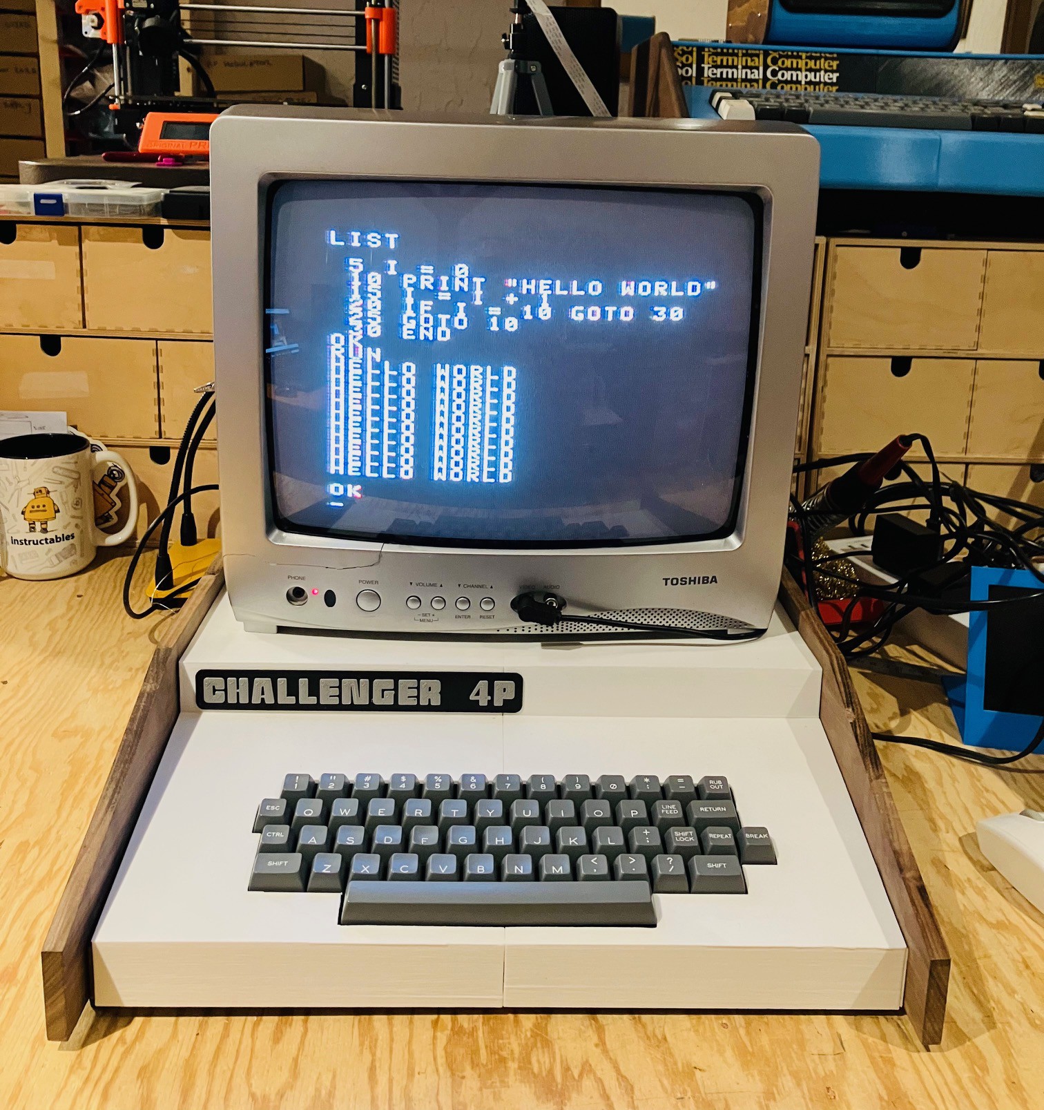
03/15/2023 at 19:23 • 0 commentsI've been trying to track down a good CRT monitor with a composite input for a while now to pair with some of my recent reproduction projects including the Challenger 4P. All in the name of authenticity. I finally found a Toshiba 13" CRT Color Television Model 13A24. While not from the 70s (more like 2005) it has a nice retro look IMHO.
![]()
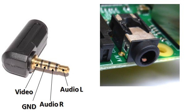
On the Raspberry Pi 4, the composite out signal is on the 3.5 mm jack along with the audio out signals. There are a number of 3.5 mm jack to RCA cables available online, but for the most part they are setup for camcorders. The pinout for the Pi jack is slightly different. Here is the Pi setup.
![]()
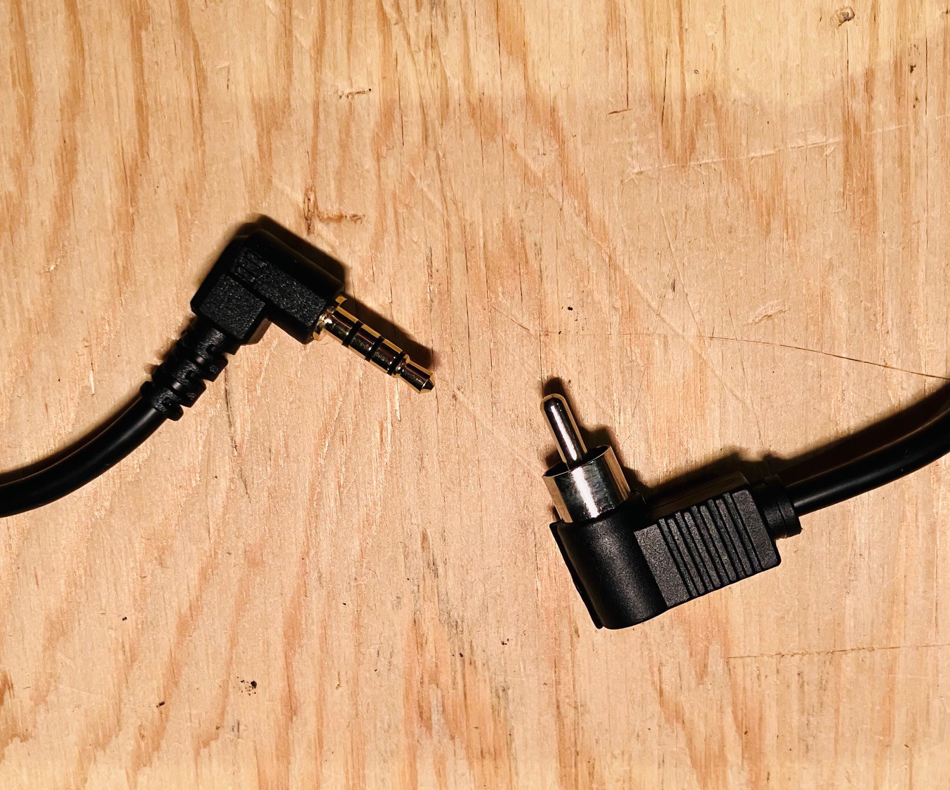
Since I only needed the composite video and no audio I made my own cable with just the one signal plus ground.
![]()
To setup for composite out (NTSC in may case) I uncommented the following lines in the /boot/config.txt file on the Raspberry Pi.
# setup for NTSC video
sdtv_mode=0
sdtv_aspect=1
enable_tvout=1
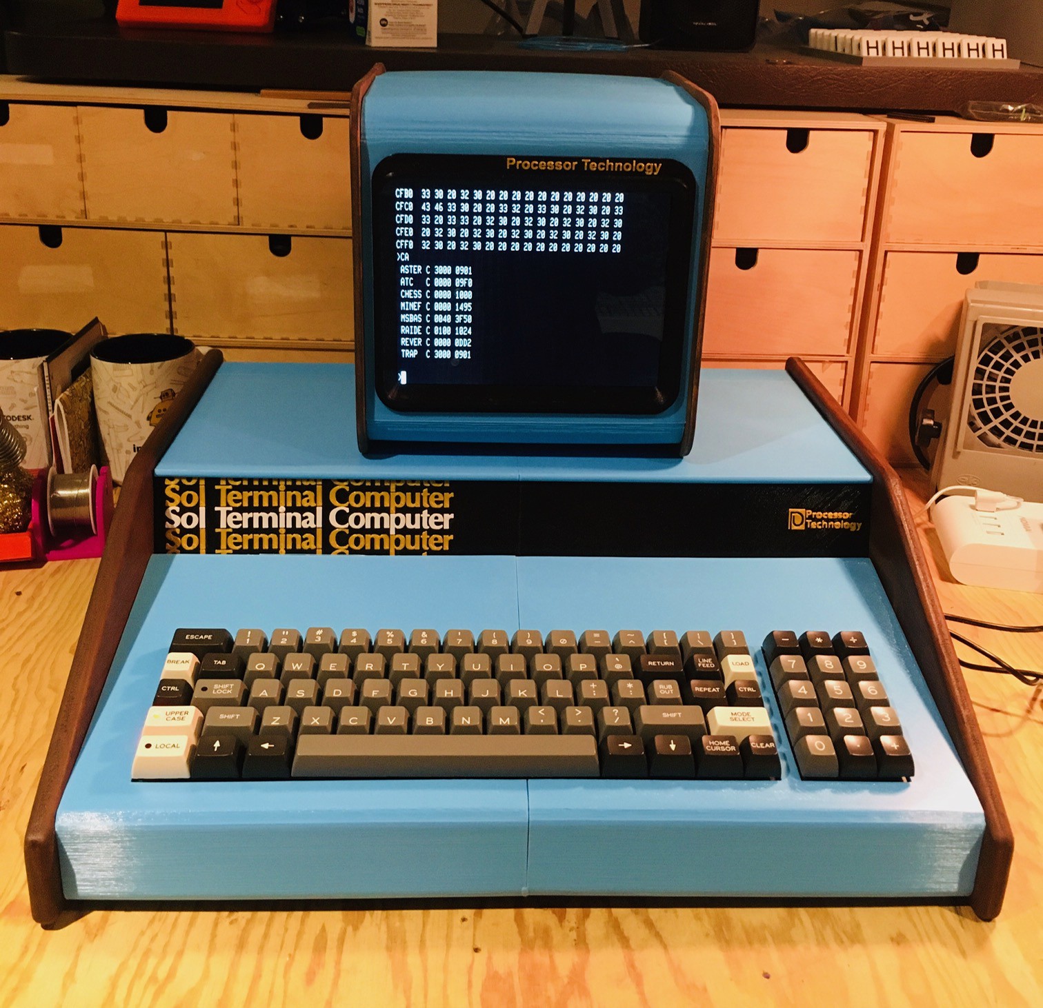
As can be seen above the TV works great, so far as it goes. I had forgotten how crappy text looks on a composite monitor. While a CRT is much more authentic, the "fake" monitor that I made for my Sol-20 Reproduction, using a period appropriate 4:3 LCD panel, is sure a lot easier on the eyes.
![]()
-
Final Assembly
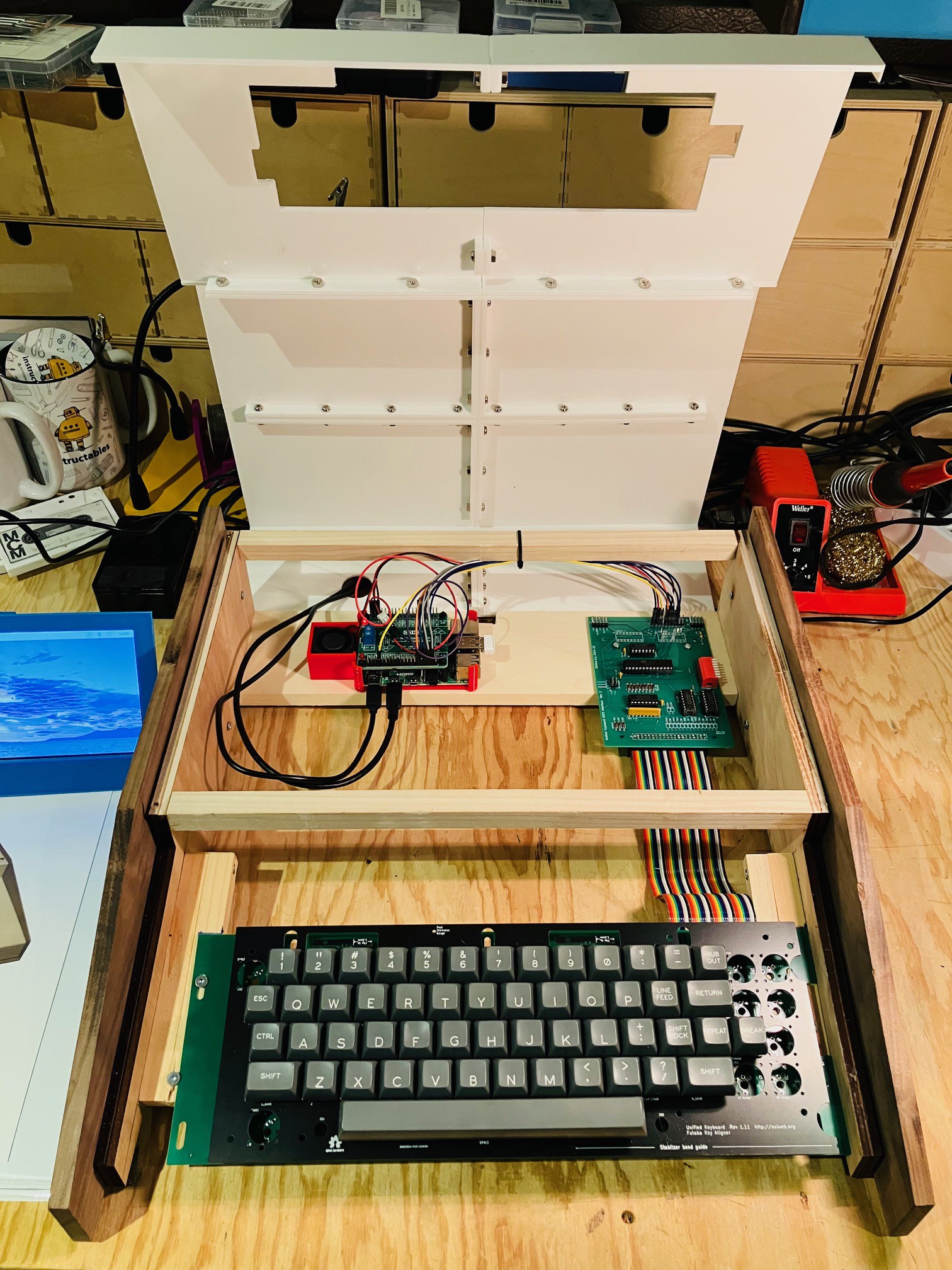
03/02/2023 at 23:05 • 0 commentsThe final assembly is pretty straight forward. I remounted the keyboard. I had already tweaked the keyboard location to correspond with the keyboard cutout on the top panel. I attached the keyboard encoder to the 4 inch cross-bar with a couple of #4 - 1/2 inch wood screws making sure that the 40 pin male connector on the encoder lined up with the 40 pin male connector on the underside of the keyboard. I made a 40 pin female to female IDC flat ribbon cable about 280 mm long and connected the encoder to the keyboard.
![]()
I also printed a "caddy" (red) to hold the Pi 4 in place and added a small 30 mm x 30 mm x 10 mm blower fan for good measure to keep things cool. The fan I used is from Amazon: GDSTIME 3cm 30mm x 10mm 5V DC Brushless Small Blower Cooling Fan, with Dual Ball Bearings. The fan and the keyboard will be run off of the Pi's power supply. The Pi and the caddy are secured in place to with two sided tape.
I ran the Pi power and HDMI cable in through the hole in the back of the case, then dropped the top panel into place.
![]()
And that's it. There is still some work I want to do on the emulator, I am still waiting for the sheet metal version of the top panel, and I am still on the lookout for a period appropriate composite monitor, but the hardware is basically done.
-
Systems Integration
02/28/2023 at 01:38 • 0 commentsWell the case is done, the keyboard is assembled, and the Challenger 4P emulator is running on the Raspberry Pi 4. I guess it's time integrate all the pieces. To that end the only real task is to wire the keyboard to the Pi and write the emulator Python code to read the hardware keyboard keys.
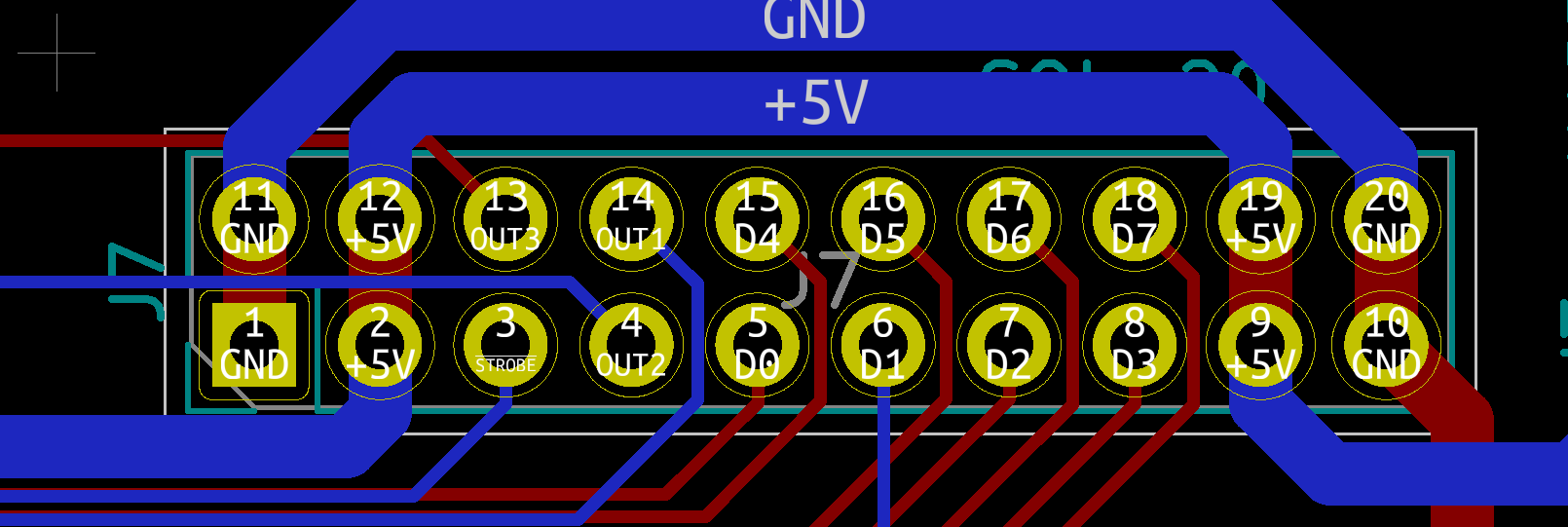
We are ready to wire the keyboard to the Pi. I'm using the header on the encoder labeled SOL-20. The pinout looks like this.
![]()
The keyboard encoder is expecting 5V while the Raspberry Pi 4 operates at 3.3V. So to overcome this I purchase a Voltage-Level Shifter Module from Amazon.
![]()
Here is how I wired the keyboard. Note that for the exception of +5V and GND lines which are wired to the 3.3V side or the level shifter, all of the other connections are wired to the 5V side.
Keyboard Encoder Raspberry Pi Description 5V 5V Power GND GND Ground D0 GPIO5 Key 0 bit (low) D1 GPIO6 Key 1 bit D2 GPIO12 Key 2 bit D3 GPIO13 Key 3 bit D4 GPIO19 Key 4 bit D5 GPIO16 Key 5 bit D6 GPIO26 Key 6 bit D7 GPIO20 Key 7 bit (high) STROBE GPIO4 Key ready on falling edge.
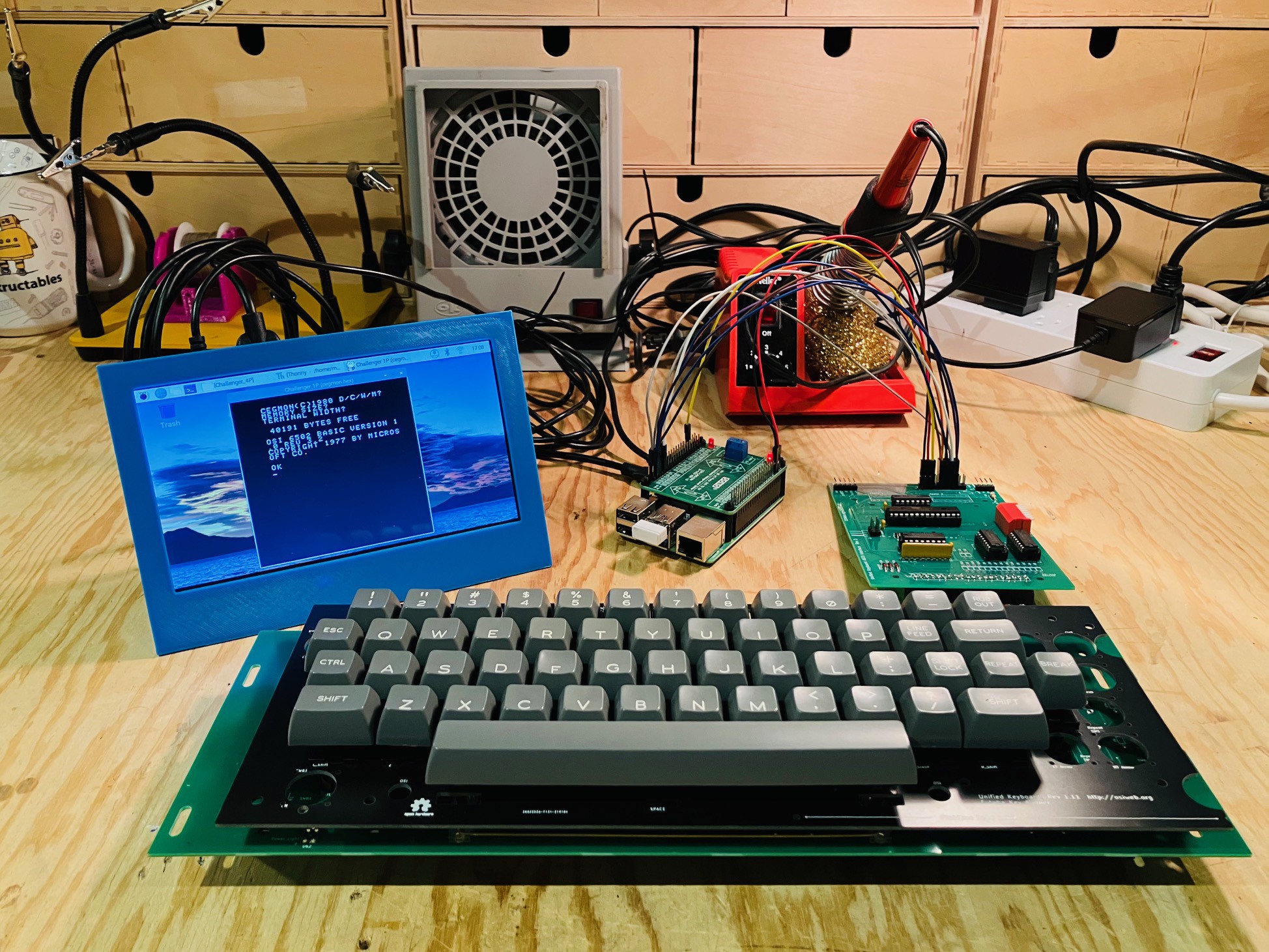
Once the wiring was complete I update the emulator's keyboard.py code to detect and process key presses from the keyboard. Note that you can still run the emulator without attaching the "special" keyboard and just use the PC's keyboard. I have posted the updated keyboard.py file to github.Here is what my little integration test looks like.
![]()
The emulator can be seen running on the small LCD screen. Keyboard seems to be working well. Ready now to insert everything into the case.
-
Getting a Second Skin
02/22/2023 at 19:53 • 2 commentsEvery Tuesday night my local makerspace (Kwartzlab) opens up to the public. People can get tours, seek member's advice, or apply for membership. Members come on Tuesdays to catch up with other members or work on their latest projects. I really missed Tuesday Open Nights (TON) when we had to suspend them during the height of Covid. Well TON is back baby, better than ever.
Last night, at TON, a maker friend told me about a company out of Spain called LaserBoost. They have a process to seamlessly combine laser cutting sheet metal with bending. You only need to submit a single STEP file of your part to get an instant quote. My friend showed me a part they had done with LaserBoost for a Famicom reproduction they are working on. Very cool (the service and the Famicom project). There are a few similar services in the US but after a quick sampling it looks like they are much more expensive.
So I started thinking about my Challenger 4P project. Don't get me wrong, I'm very happy with my 3D printed case top. It's solid (can support the weight of a monitor) and looks good. But I've always wondered how hard it would be to create a more authentic sheet metal skin. Kwartzlab does have tools for bending sheet metal but at this point no equipment for cutting sheet metal. LaserBoost gives me a way to produce a sheet metal skin with minimal effort (not that I am opposed to learning to work more directly with sheet metal at some future date).
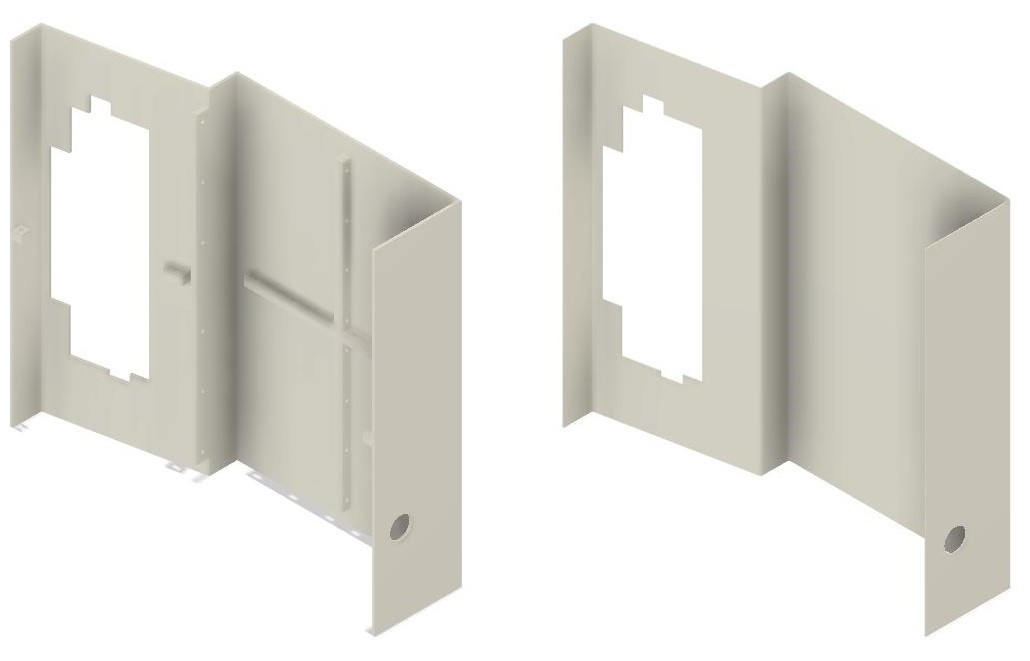
I started with my Fusion 360 3D printed skin model and removed all the braces (mostly just rolling back the Fusion 360 history). Then I reduced the case thickness from 3 mm to 1.2 mm.
![]()
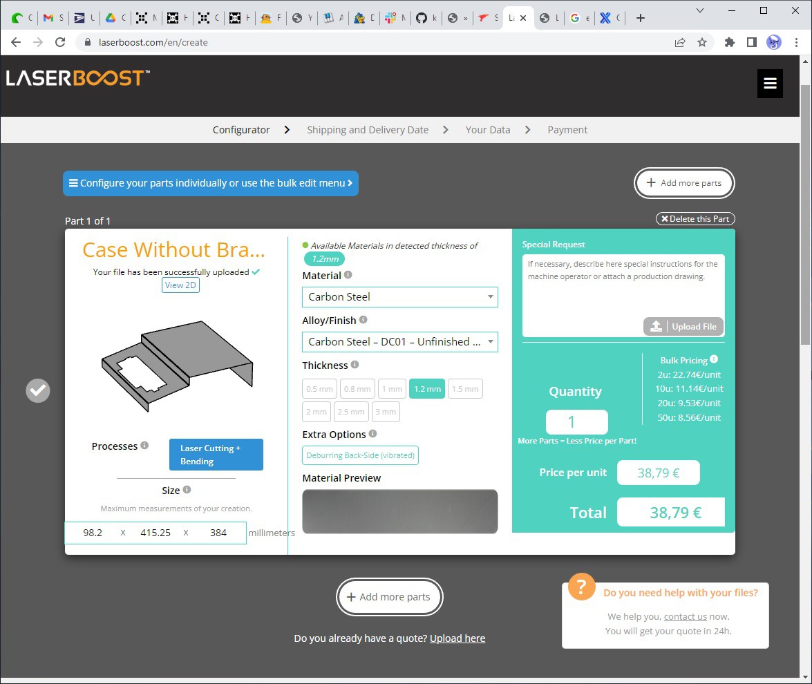
I saved the modified model as a STEP file which I loaded into the LaserBoost instant quote application. I only had to select the Material that I wanted to use (unfinished carbon steel). The application figured out everything else!
![]()
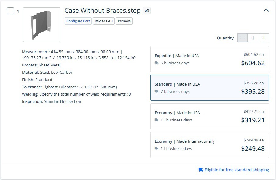
And voila my quote 38,79 € ($41.27 US or $55.77 CAD). In my eyes that is a very reasonable price for a one off, so what's the catch? I did mention that LaserBoost is located in Spain right? It turns out that shipping a largish piece of fabricated sheet metal via DHL (the only international shipping option) is 56,90 € ($60.32 US or $81.81 CAD). Having said this, the quotes I got from the US services that I sampled were so much higher that even with free shipping from the US could not offset the cost difference. For instance here is one of the other quotes from a US company which shall not be named.
![]()
Now I think the quotes are for the same outcome, but I'm new enough at this stuff to have messed up somehow.
At the end of the day I decided to place the order with LaserBoost. With shipping it's a little pricey but I'm anxious to see the result. To get the best price I have set a March 30th delivery date so I have a bit of a wait (like the second quote above, LaserBoost charges extra for "expedited" delivery on a sliding scale). Stay tuned.
-
Updating PyGame
02/21/2023 at 16:24 • 0 commentsI noticed that there was a problem with the emulator. The keyboard was not working correctly with shifted keys. It turned out to be an issue with the way that I implemented the keyboard handler and the version of PyGame that came pre-installed on the Raspberry Pi OS distribution. Fixed by updating PyGame with the following command.
pip install pygame --upgrade
-
Prepping the Pi
02/19/2023 at 17:44 • 0 commentsSo far, all of the Challenger 4P emulation development has been done on my Windows laptop using LiClipse. LiClipse is an extension of the Eclipse development environment. I used Eclipse for the last 25 years of my software development career so I'm familiar with it, and chose the LiClipse variant because it came bundled with PyDev, a Python IDE for Eclipse.
Now it's time to move the emulator to the Raspberry Pi 4 that will power my Challenger 4P reproduction. One of the reasons that I chose Python for this project was this portability. When I started this project last August, I had hoped that the supply issues which made Pi 4s virtually unobtainable would have been fixed. No such luck. I looks like Pi 4s will not reach unconstrained availability until Q3 2023. Sigh. Fortunately one of my mates at my local makerspace (Kwartzlab) had one to spare that I could use until such time as I can buy one for myself.
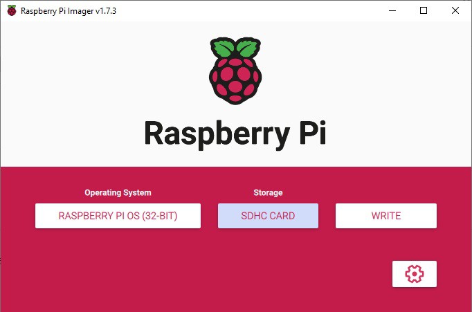
I'm not going to detail getting the Raspberry Pi OS onto the Pi 4 as there are a lot of guides out there like this one from tom'sHARDWARE. Basically I just loaded a Raspberry Pi OS image onto a 32G microSD card using Raspberry Pi Imager.
![]()
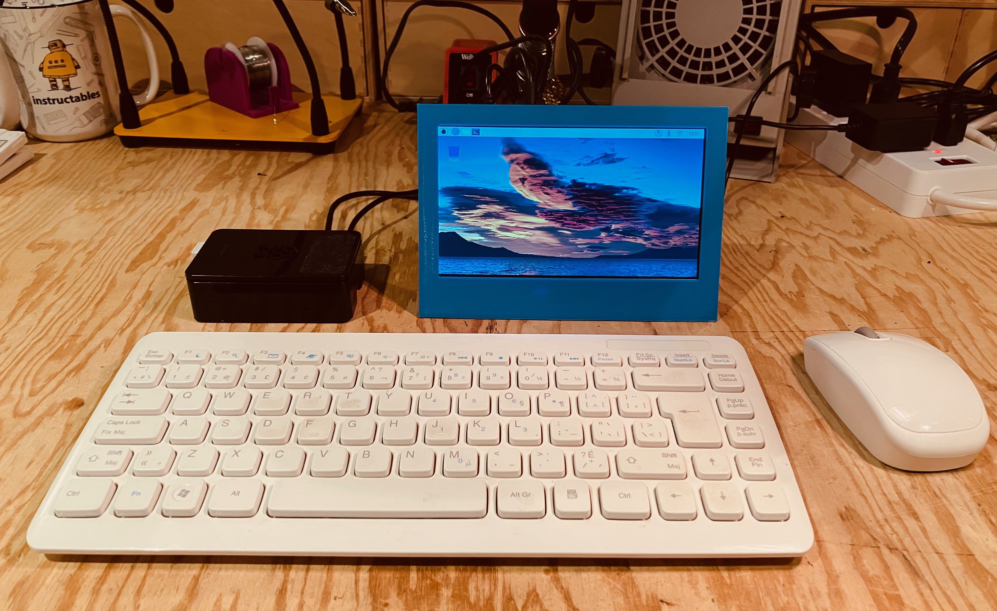
I plugged the microSD card into the Pi 4 to which I had attached a small LCD screen, wireless mouse, and keyboard. You could do the installation completely "headless" as outlined here, but I prefer to do the configuration interactively with this the setup. I powered up the Pi and went through the initial configuration dialogs to set the login user, keyboard, language, locale, and wireless connection. Super easy.
![]()
Ultimately the Pi will be run headless with no keyboard or mouse. There will however be a display to show the emulator's screen. My preference is to use VNC to accomplish this. Raspberry Pi OS ships with RealVNC pre-installed. So the first thing that I did after the basic OS had been installed was to setup a virtual server for the RealVNC client to connect to. The easiest way I have found to do this is to add the following lines to the end of the /etc/rc.local file before the exit 0 on the Pi.
# Setup a virtual screen for the VNC server.
sudo -u xxxxx vncserver -randr=1920x1080
xxxxx is the login user that you setup to access the Raspberry Pi. Set the screen dimension (randr=) to be the same as the machine that you will be accessing the Challenger 4P from.
I found in my setup is that there were a few issues accessing this server with the RealVNC client on my Windows machine. The first was that the menu bar at the top of the desktop was missing. To restore the desktop menu bar enter the following command.
sudo apt-get remove --purge alsa-base pulseaudioOn a similar note the title bar on open application windows and the corresponding windows controls (v ^ x) were missing as well. To fix this I edited the desktop.conf file,
sudo nano /etc/xdg/lxsession/LXDE-pi/desktop.conf
and changed the line:
window_manager=mutter
to
window_manager=openbox-lxde-pithen saved the changes.
With these changes made reboot the Pi 4 for them to take effect.
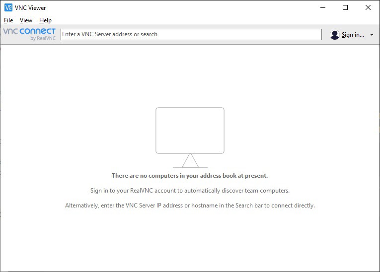
I downloaded and installed the RealVNC client on my Windows machine. Run the RealVNC VNC Viewer. You should see this window.
![]()
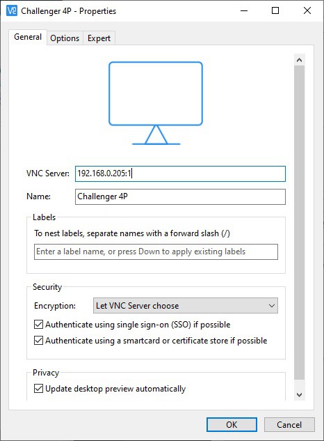
From the menu select File->New connection... to bring up the following dialog. Add the Server address and common name then click OK. Note the :1 added to the server address. This references the instance of the VCN Server running.
![]()
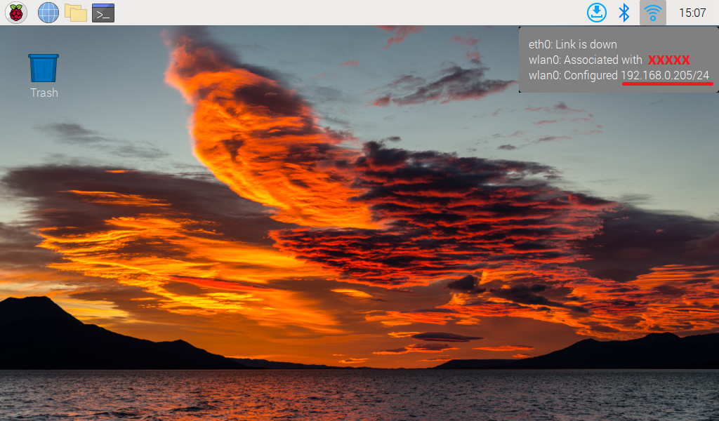
To find the VNC Server address you can just hover over the WiFi (or network) connection on the server desktop.
![]()
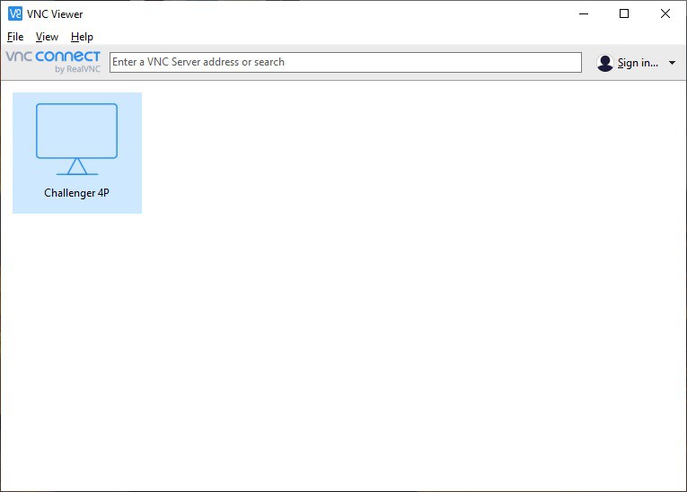
From the main VNC Viewer window double click on the Challenger 4P connection just created.
![]()
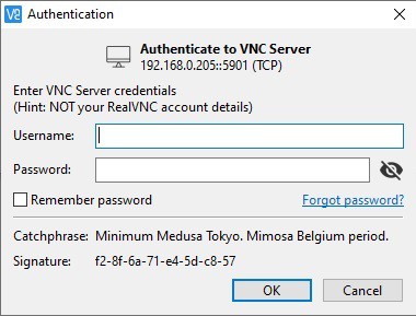
The first time you attempt a connection you will be prompted to enter the Raspberry Pi's login credentials. Check Remember password if you don't want to have to do this every time you connect. Enter the credentials and click OK.
![]()
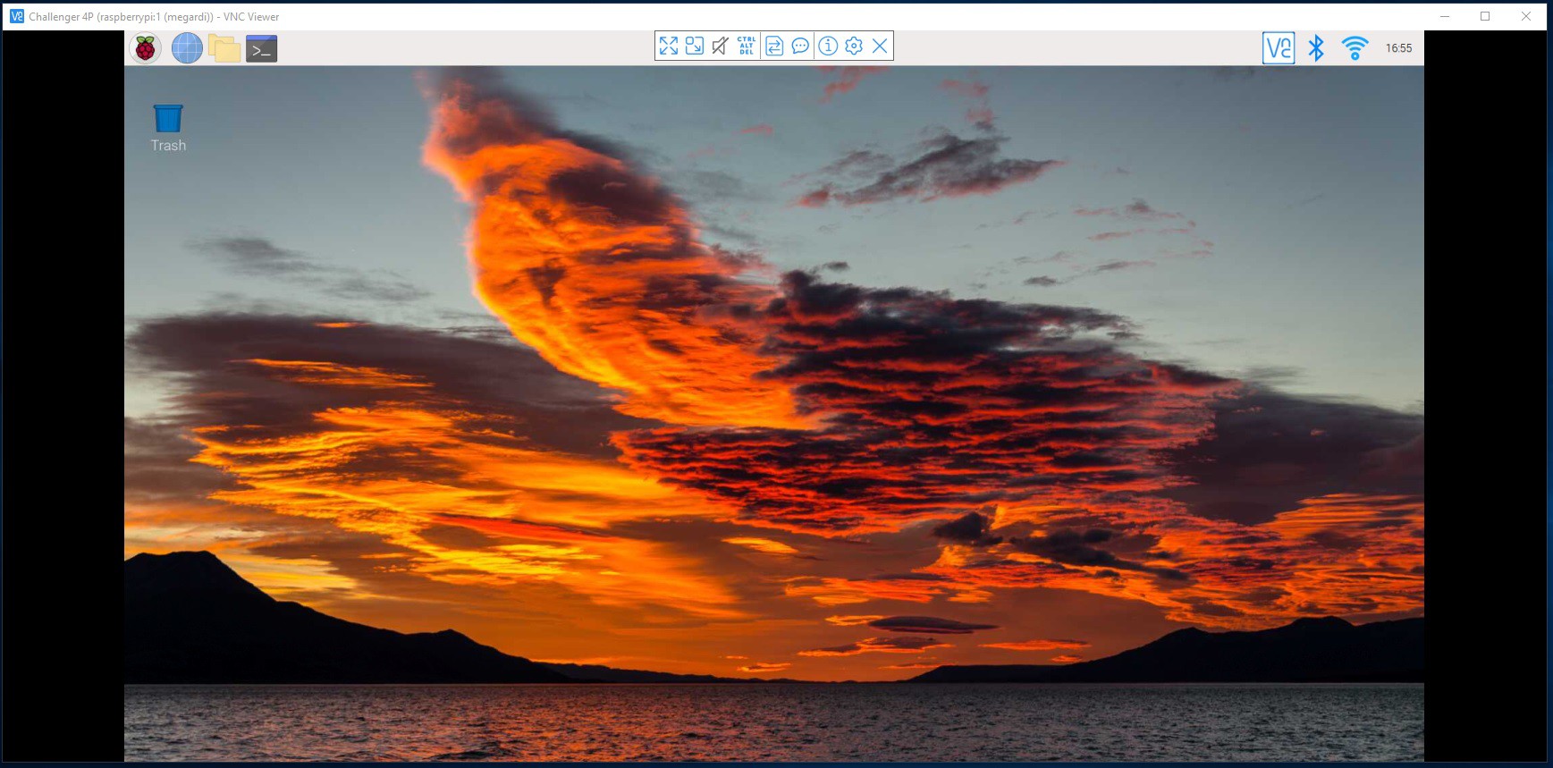
You should see an instance of the Pi 4's desktop.
![]()
To get the emulator onto the Pi 4 you can simply clone the repository from github. Open a terminal window and enter the following command:
git clone https://github.com/kidmirage/OSI-Challenger-1P-ReproductionYou should see a response similar to this:
Cloning into 'OSI-Challenger-1P-Reproduction'...
remote: Enumerating objects: 70, done.
remote: Counting objects: 100% (3/3), done.
remote: Compressing objects: 100% (3/3), done.
remote: Total 70 (delta 0), reused 0 (delta 0), pack-reused 67
Receiving objects: 100% (70/70), 67.60 KiB | 1.04 MiB/s, done.
Resolving deltas: 100% (28/28), done.To run the emulator run the following commands:
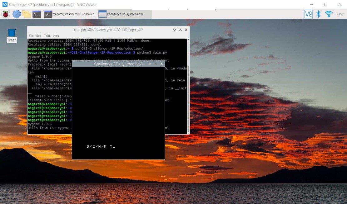
cd OSI-Challenger-1P-Reproduction/
python3 main.py
You should see the Challenger 4P emulator popup.
![]()
There is still some work to do on the emulator but having it running on the Pi 4 is a big step forward. Next step will be to integrate the hardware keyboard.
-
Case Closed
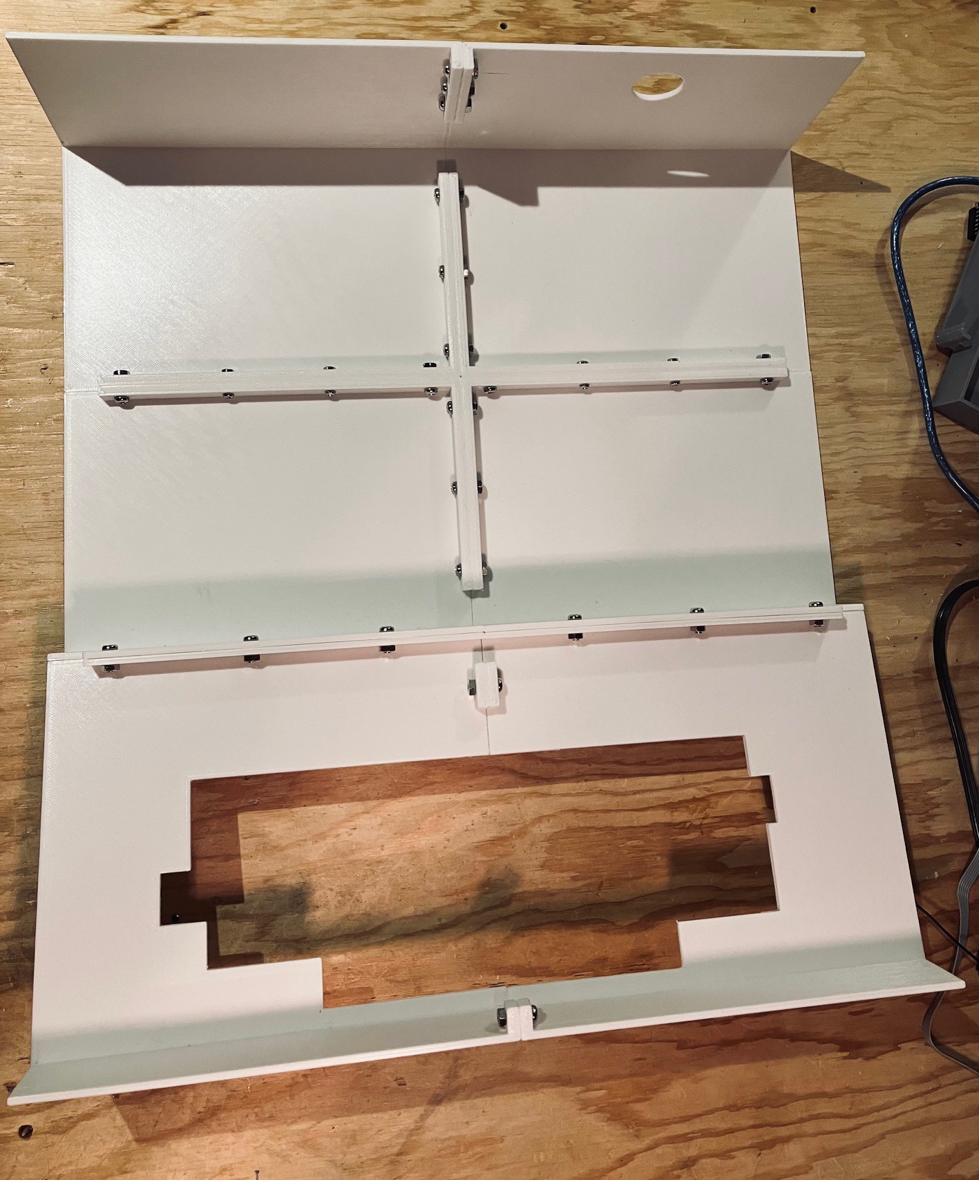
12/15/2022 at 15:33 • 2 commentsThe case parts printed well. There were a couple of places where the print pulled up a tiny little bit in the corners, despite a 10 brim, but not very noticeably. I joined the pieces to together with M4 x 12 mm bolts and nuts.
![]()
Then I fitted "skin" onto the frame. With the skin on I was able to adjust the keyboard to fit inside of the cutout and screw it down. To Steve's credit (the measurer) and Dave's (the keyboard maker) it fit perfectly. All I had to do then is 3D print a logo and voila!
![]()
Even though not necessary, for authenticity I thought about adding the 14 or so screws that can be seen on the top of the original's case, but in the end decided that I liked the cleaner look of what I have.
So this marks a milestone in my project. With the case complete I was able to change the primary photo for this project post to be my reproduction's, replacing the original's photo that I was using as a place holder.
OSI Challenger 4P Reproduction
I am making a full sized Challenger 4P reproduction, a 6502 based personal computer from the late 1970s.