The most recent design files are kept on AutoDesk Cloud which you can access here: https://a360.co/3SpmaK8
The extruder uses the 16 mm compression screw and barrel from RobotDigg which 57 mm flange is compatible with Nema 23/24 size steppers. You will need to choose a stepper with adequate down gearing for enough torque. The needed torque depends on the flow properties of the polymer you would like to extrude and of course on the targeted speed. A 25:1 reduction is a good spot to start with.
You can buy different sized nozzles from RobotDigg.
2
Safety Warnings
The Badass Pellet Extruder is powered by mains voltage which can cause a lethal electric shock if connections short circuit for any reasons! Therefore it is mandatory to have experience in building safe electrical circuits. Do not ignore this warning!
All metal parts of the extruder need to be grounded to Protective Earth and the electricity powering the heaters should go through a residual-current relay which might be your lifesaver if things go south.
The maximum temperature of the heater bands is around 300 deg C which can lead to serious burn injuries and/or a fire. Those heaters will need an insulation blanket. Do not operate the extruder without them and remember that due to the large thermal mass of the extruder it will stay hot for a long time after power is shut off.
Ideally only the nozzle is exposed and hot.
This extruder is a prototype design. We do not bear any responsibility for loss/damage of life, health or property that results of using this extruder. Please be responsible and careful!
We expect you to have the expertise to connect the extruder to the mains grid, therefore we won't give any advice on how to do that.
3
Pre-requisites
You will need basic tools like metric Allen keys, some pliers, screwdrivers, hacksaw etc. A Dremel is also very handy to have. You'll need to cut the mixer screw to an appropriate length and also to remodel the tip of the screw. Have some cutting discs and grinding tips available.
Some power tools like an electric drill come handy as well. Depending on how you will want to terminate the wiring you will need a soldering iron too. The soldering iron is also needed to insert some heat inserts.
Beyond the things mentioned above you should have access to a 3D-printer.
4
Preparation
Metal parts
Two components of the extruder need to be milled aluminum because of the torsional force that the extruder motor applies to them. You can also 3D-print these parts but they will most likely break sooner or later.
3D printed parts
As you want to have the inner surfaces of the 3D printed parts as smooth as possible for frictionless transport of the plastic pellets, we suggest to post-process the printed parts. This can be done by sanding, but especially the central funnel of the reservoir might turn out tricky to sand. We had great success with ABS printed parts which we smoothed out with Aceton vapors.
Please print the parts with temperature resistant plastic like ABS or PETG. If you choose to print the extruder bearing cup and the extruder bracket, please choose a tough, hard and temperature resistant plastic like PETG-CF, Nylon-C or PC.
5
Extruder stepper motor assembly
Screw the extruder nozzle in the barrel to prevent the extruder screw from falling too deep into the barrel
Slide the angular contact bearing on the compression screw until it is flush with the small flange
Insert the 5 x 5 x 20 mm key into the slot at the other end of the compression screw
Push the coupling on the compression screw. Take care you push it all the way down until the end of the screw touches the couplings' rubber
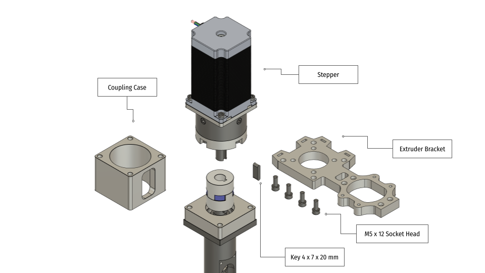
Next prepare:
Nema 23/24 stepper motor
Coupling case
Extruder bracket
Key 4 x 7 x 20 mm
4 pcs M5 x 12 Head Socket Screws
Attach the extruder bracket to the planetary gearbox with four M5 x 12 screws.
Press the 4 x 7 x 20 mm key on the gearbox shaft.
Put the coupling case between the barrel and the stepper and press the stepper shaft into the coupling. Rotate the couplings' setscrew towards the opening of the case.
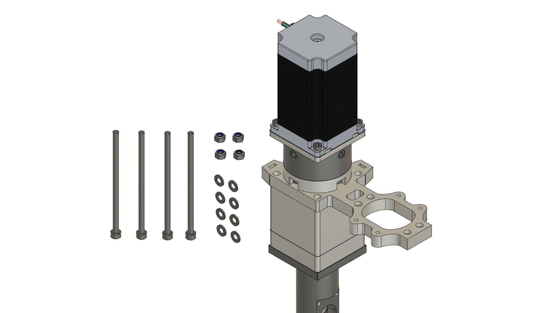
Next prepare:
4 pcs M5 x 100 Socket Head Screws
4 pcs M5 Locknuts
8 pcs M5 Washers
Fix the extruder assembly with 4 M5 x 100 mm Socket Head Screws with the screw tips pointing towards the extruder nozzle.
Attention:
Please be sure that the coupling case opening does not point towards the hopper end of the extruder bracket. If so, you won't be able reach the coupling setscrews. The most reachable place for the opening is on the backside of the extruder.
6
Heater Band Assembly
The extruder has three different temperature zones:
Feed
Compression
Metering
Melting of the plastic is done mainly in the compression zone which is usually driven with the highest temperature. It's not just the heat that melts the plastic but also the friction caused by the compressing nature of the screw. Melting prior this zone is not desirable because it would have a negative effect on the back pressure in the barrel and it could lead to clogging at the barrel entry. Therefore the feed zone is kept coldest of the three zones. Once the plastic has been melted in the compression zone the temperature can be lowered to a desired level for extrusion through the nozzle. Ideally the nozzle would have an own temperature zone but this setup can worked for us just fine.
Next prepare:
3 pcs ID 35 x 40-50 mm Mica heaters bands (around 200W each), please choose heaters with built-in temperature sensors. We've had great success with PT1000 sensors.
Unscrew the extruder nozzle and slide in the barrel band heaters. No need to tighten the screws yet. We will adjust the position later. Then you can screw in the nozzle again.
7
Heat Break Assembly
Above the feed zone we want to have a clear drop in temperature to ensure proper function of the feed zone. If the temperature rises too high, it can lead to clogging as the plastic pellets start to stick together even before they enter the barrel. Therefore it is crucial to have the temperature dissipated between the uppermost heater band and the entry point of the barrel. To achieve this we are going to use three heat sinks with cooling fans.
Luckily there are heat sinks on the market that fit perfectly on the barrel. Just look for RC-motor heat sinks for the 540 motor class. As for the fans, we recommend to choose 40 x 40 x 30 mm quality instead of those that often come with the heat sinks.
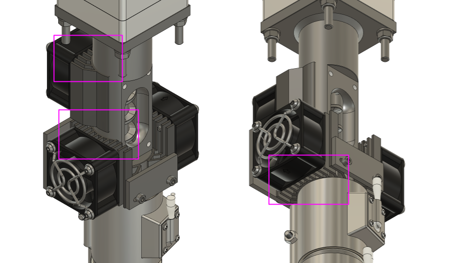
First we need to prepare the heat sinks by cutting off a few pieces. These apply only to two heat sinks, one remains as it is.
1. Start by sawing or cutting with a Dremel a 20 x 20 mm section off the heat sink as seen in the middle down below.
2. Then finalize it by cutting off the round sections that extend downwards from the fins as seen on the right side down below.
3. Repeat these steps mirrored on the second heat sink.
4. Next drill & tap M3 holes on the sides of the heat sink. Ca. 5 mm offset from the front/back edge and ca. 7 mm from the top edge. Also one hole on the other side.
5. Repeat for the second heat sink. The third remains as it is.
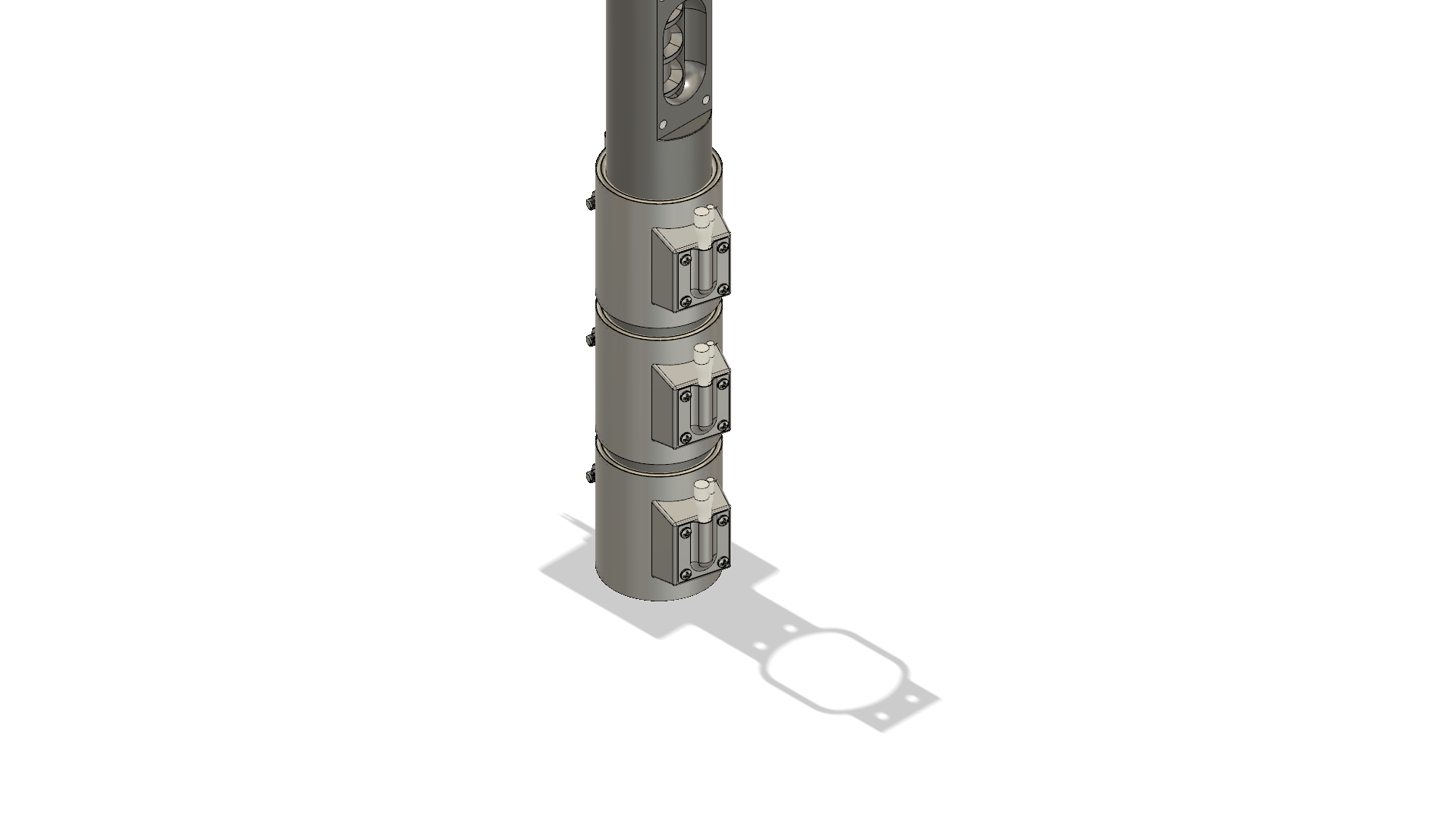
Finally we should have three heat sinks with attached fans ready for assembly.
6. Next we'll need to make two plates from 3 mm thick aluminum that hold together two of the heat sinks.
7. When attaching the duo heat sink to the extruder, press them together before tightening the left screw.
Fully assembled the heat break looks like this.
And from the back side
Attention:
Please make sure to leave a ca. 5-7 mm gap between both heat sinks and between the bottom heat sinks and the uppermost heater band to allow proper air flow through the heat sink fins.
8
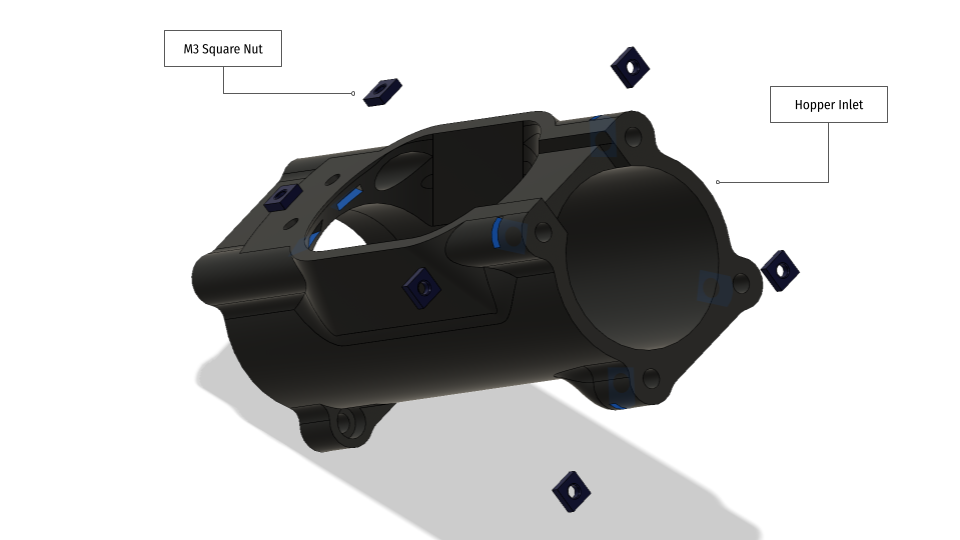
Hopper Assembly
Now we start adding the components for the material feeding system. These include the hopper, the hopper inlet and the joint body that connects the hopper with a material reservoir. There will be also a motorized feeding system.
Prepare:
6 pcs M3 Square Nuts
2 pcs M4 x 10 mm Socket Head Screws
2 pcs M4 x 20 mm Socket Head Screws
3D-printed hopper
1. Next, fix the hopper on the barrel. The screw holes on the hopper are intentionally kept slightly bigger than necessary due to the manufacturing tolerances of the barrel.
2. Put the square nuts in the slots of the hopper.
3. Next prepare the hopper inlet section by inserting the M3 square nuts into the designated slots. There are 6 slots in total. Two inside the inlet and four outside.
5. Insert 4 M3 square nuts into the slots of the joint body and attach it with 2 M3 x 8 mm Socket Head Screw to the hopper inlet.
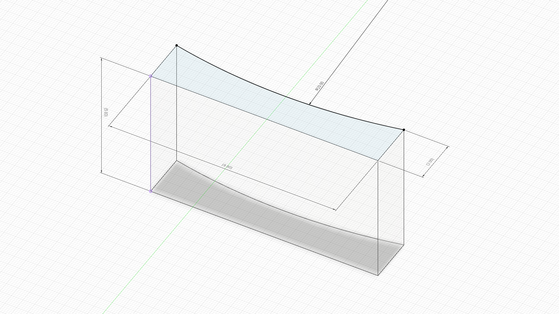
6. The sensor base needs to be sealed against plastic dust with a small transparent plastic cover which allows the IR light to pass through. The easiest way to make the part is by laser cutting it from acrylic but it works well enough if you cut a rectangular piece with a saw or a Dremel. The dimensions should be 10 x 6 x 2 mm so you have some margin to sand it down a little bit for a snug fit.
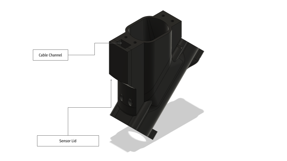
7. Now insert the dust cover into the opening that goes all the way to the hopper channel. You should fix it with a few drops of glue.
8. Put the sensor in place.
9. Attach the Grove cable to the sensor.
10. Close the sensor compartment with a lid.
11. Route the Grove cable through the channel in the extruder bracket.
12. Attach the inlet to the extruder with two M3 x 20 mm Socket Head Screws (external) and two M3 x 30 mm Socket Head Screws (internal).
13. Finish the hopper assembly by tightening the top section of the hopper to the extruder bracket with 4 M3 x 25 mm Socket Head Screws.
9
Feed Screw assembly
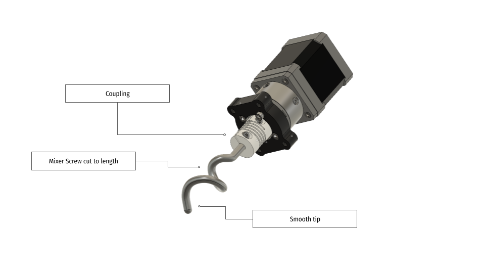
We ended up designing a force feed system for the extruder to ensure stable operation with any sort of plastic under all circumstances. Gravity wasn't just working well enough. For this job we used a secondary geared stepper motor which is driving a mixer screw, or actually a part of it.
Prepare the geared Nema 17 stepper motor. Again as a rule of thumb a gear reduction in the rage of 25:1 to 100:1 works fine.
1. Attach the bracket with 4 M3 x 8 mm Socket Head Screws to the gearbox.
2. Next fix the coupling on the gearbox shaft.
Usually the mixer screws of kitchen appliances are too long and they have a hooked tip which potentially would cause plastic to stick and lead to clogging. In order to prevent that from happening the tip needs to be cut off and the remaining part to be smoothed out. Try to cut the screw in a way that the tip points towards the barrel. A Dremel is here a very useful tool. The screw should extend through the whole inlet section.
3. Use 4 M3 x 20 mm Socket Head Screws to fix the stepper to the hopper.
And this is how the Badass Pellet Extruder should look like after the hopper assembly.
10
Granulate Reservoir Assembly
We will now add a small reservoir for plastic pellets on top of the hopper section. The reservoir has a material level sensor to trigger the dispensing system once the level has dropped below the threshold.
Prepare:
3D printed Separator Adapter Plate
3D printed Reservoir (Separator)
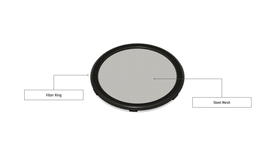
3D printed Filter Ring
3D printed Reservoir Lid
4 pcs M3 Square Nuts
4 pcs M3 x 20 Socket Head Screws
4 pcs M3 Heat Inserts
4 pcs M3 x 8 Socket Head Screws
8 pcs M3 Washers
4 pcs M3 Locknuts
4 pcs M3 x 15 Socket Head Screws
50 x 50 mm fine steel mesh
Some super glue and/or plastic glue
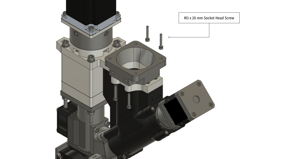
1. Put the separator adapter plate on top of the hopper and insert 4 M3 square nuts into the slots on the side.
2. Fix the adapter plate with 4 M3 x 20 Socket Head Screws.
3. Take the printed reservoir and put 4 M3 Heat Inserts into the screw holes.
4. Cut a ca. OD 30 mm piece of fine steel mesh and glue it on the inside of the filter ring.
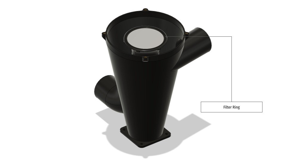
5. Press the filter ring on top the central funnel.
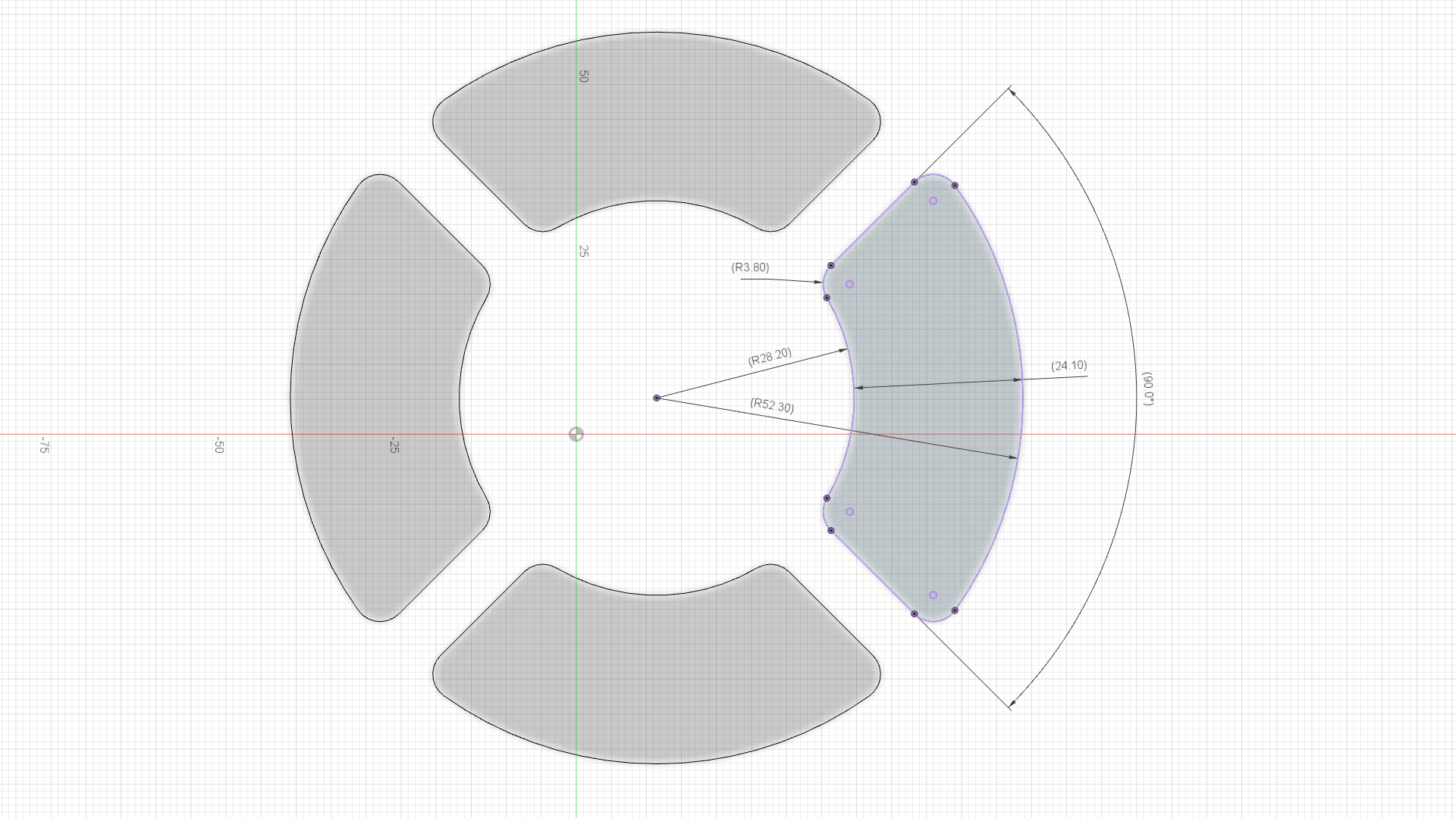
6. The lid has 4 small windows because you want to look inside :) It is optional to print the lid without them. Again if you have access to a laser cutter you can cut the pieces from transparent acrylic.
7. Tighten the lid with 4 M3 x 8 mm Socket Head Screws on top of the reservoir.
8. Fix the reservoir on top of the adapter plate with 4 M3 x 15 mm Socket Head Screw, 4 M3 Washers and 4 M3 Locknuts.
After this section the Badass Pellet Extruder should look like this.
 Atte Linna


Discussions
Become a Hackaday.io Member
Create an account to leave a comment. Already have an account? Log In.