 Atte Linna
-
11Power Cable Connector
In this section we will add a base for an additional electronics box and the power cable connector which will sit on the top edge of the base.
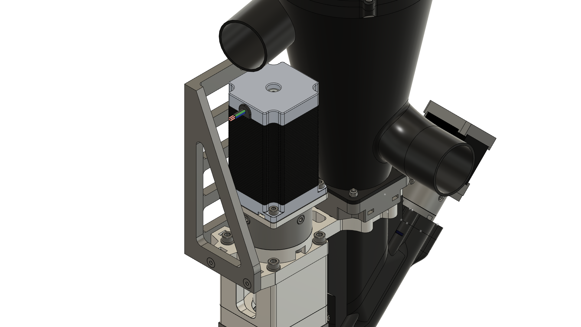
On the right side of the extruder you can attach a small box for electronics and cable termination. The heater band cable termination is done in a separate box beneath the hopper.
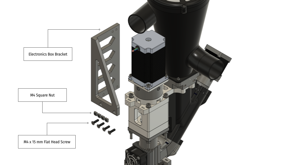
Prepare:
- The bracket
- 4 pcs M4 Square Nuts
- 4 pcs M4 x 15 mm Flat Head Screws
![]()
1. Place 4 M4 Square Nuts into the designated slots of the extruder bracket.
2. Attach the bracket to the extruder with 4 M4 x 15 mm Flat Head Screws.
![]()
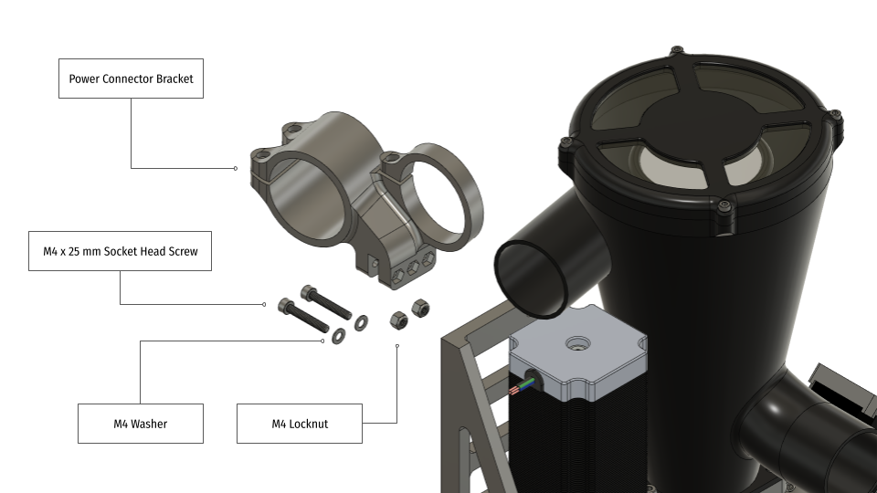
Prepare:
- The Power Connector Bracket
- 2 pcs M4 x 25 mm Socket Head Screws
- 2 pcs M4 Washers
- 2 pcs M4 Locknuts
![]()
3. Press the M4 Locknuts into the two rightmost slots of the connector bracket.
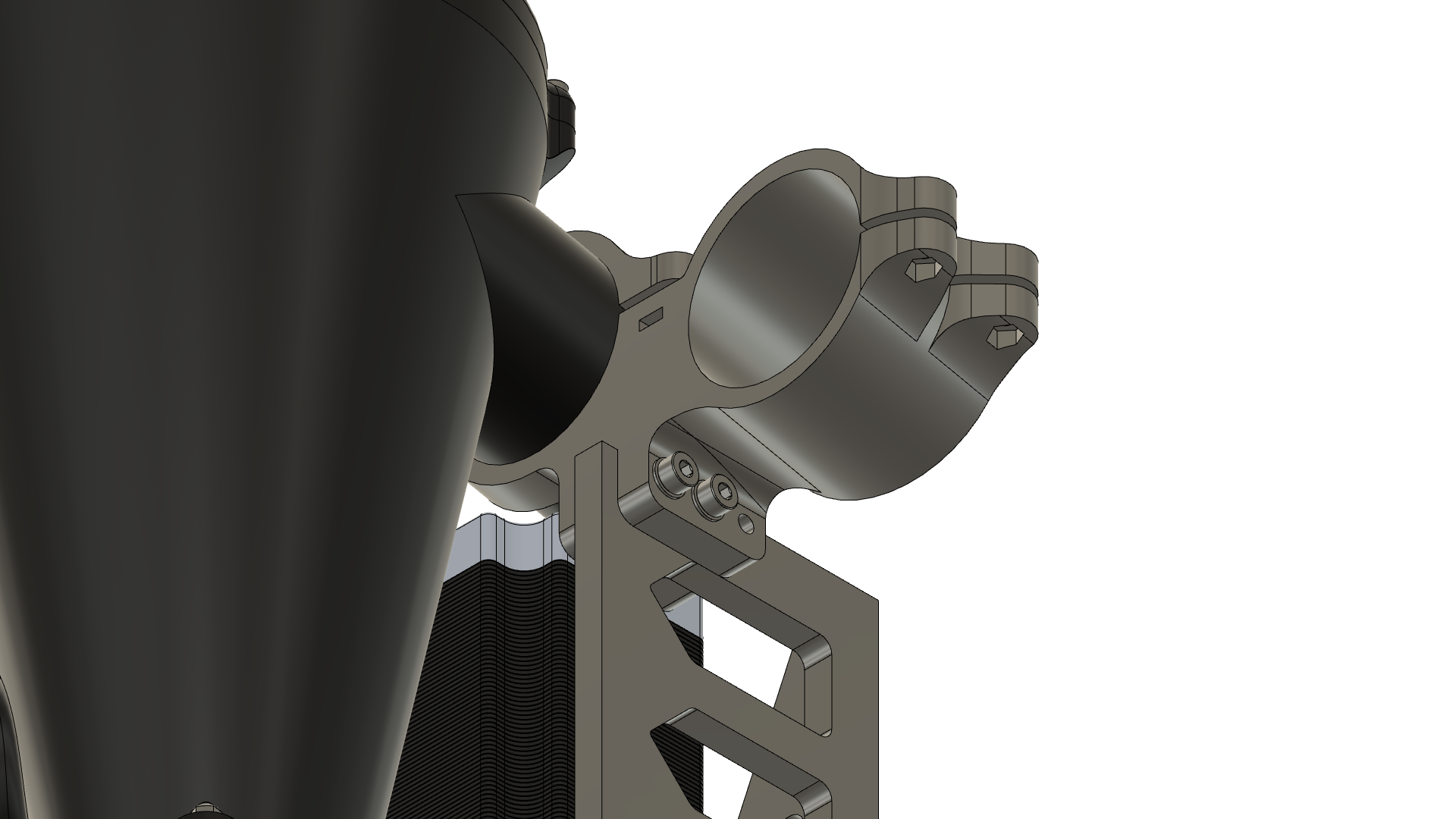
4. Slide the bracket in place. The separator inlet goes through the bracket ring where it will be fixed in the next step.
5. Screw in the M4 x 25 mm Socket Head Screws to fix the connector bracket.
![]()
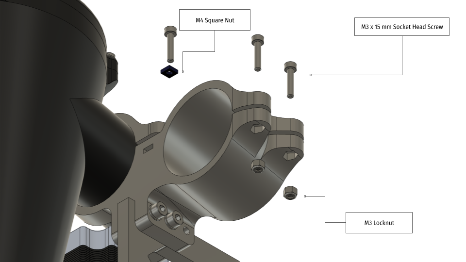
Prepare:
- 3 pcs M3 x 15 mm Socket Head Screws
- 1 pc M3 Square Nut
- 2 pcs M3 Locknuts
![]()
6. Press the M3 Locknuts into the slots on the right side.
7. Press the M3 Square Nut into the slot on the front side.
8. Fix the separator inlet in place with a M3 x 15 mm Socket Head Screw.
9. Screw in loosely the remaining two M3 x 15 mm Socket Head Screws.
![]()
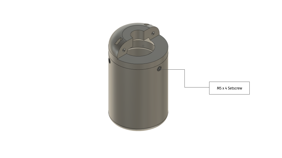
Next we need to prepare the connector housing for the power connection to the heater bands. We chose the Wieland RST2015 5-pole connector 250V/20A as the three heater bands need to be controlled individually. You might need to adapt the connector to your local requirements, so this is here only as an example.
Prepare:
- Connector (in our case the Wieland RST2015 5-pole female with screw connection)
- Connector Housing
- Cap
- Strain Relief
- 2 pcs M3 x 15 mm Socket Head Screws
- 2 pcs M3 Square Nuts
- 3 pcs M5 x 4 Setscrews (cone tip)
![]()
10. First attach the wires to the connector and fix it to the housing with its nut. Use 5-pole cable with a proper current rating. Cut the cable to a length of 500 mm.
11. Now insert the cap into the housing and align the holes with the three small dents on the flange of the cap.
12. Fix the cap in place with 3 M5 x 4 mm Setscrews.
![]()
13. Insert 2 M3 Square Nuts into the slots on the cap and finalize the housing by fixing the strain relief with 2 M3 x 15 mm Socket Head Screws.
![]()
14. Next the connector housing needs to be attached to its bracket. Tighten both screws and ensure the housing does not move if you pull it.
![]()
-
12Heater Band Cable Termination
Let's take first a look on where the power cables for the heater bands are terminated. The small box sits right beneath the hopper where the heater band cables and the power cables are connected to each other. The box itself is fixed with 2 M3 x 8 Socket Head Screws to the hopper.
WARNING:
This box is a first prototype without proper strain relief for the cables. As these cables run mains voltage you should be aware of potentially lethal results if those cables come off and short circuit or touch the metal parts of the extruder! We do not bear any responsibility for loss/damage of life, health or property! It is your responsibility to take care of proper electrical and mechanical termination of these cables. This is only a proposal for further design.
![]()
Inside the box are two kinds of screw terminals. One on the bottom for the Live lines and one Neutral line rail on the top. On the left side is an empty space for termination of the temperature sensors. We use PT1000 sensors as these work reliably on very long leads. Another method is to use K-type thermocouples but in our experience they are too prone for causing false temperature readings.
![]()
1. Cut a short piece of Neutral wire and connect one end of it to the leftmost screw terminal on the bottom and the other end to the leftmost screw terminal on the Neutral rail.
![]()
2. Connect the Live wire of the Feed Zone Heater (the topmost) to the leftmost screw terminal on the bottom.
3. The Live wire of the Compression Zone Heater (in the middle) goes to the middle screw terminal on the bottom.
4. And the Live wire of the Metering Zone Heater (next to the nozzle) goes to the rightmost screw terminal on the bottom.
![]()
Next connect the Neutral wires. Start again from the left. This time the wires are inserted through the top row holes all the way to the Neutral Rail block.
5. Connect the Feed Zone Heater Neutral wire to the 2nd terminal from left.
6. Connect the Compression Zone Heater Neutral wire to the 3rd terminal from left.
7. And finally connect the Metering Zone Heater Neutral wire to the rightmost terminal.
![]()
8. Route the temperature sensor cables to the left compartment. We use a shielded multi-strand cable for routing them combined to the controller. Use connectors/terminals of your choice.
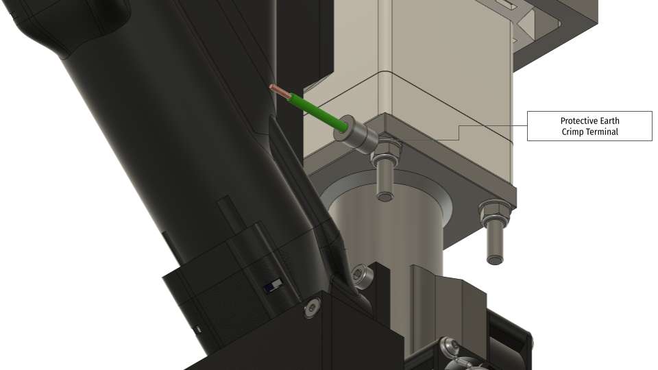
9. Last and the most important step! Connect the Protective Earth wire to good spot with contact to each metal part that could go Live if something goes wrong. One of such spots is the M5 x 100 mm holding together the extruder assembly. Please check the continuity of Protective Earth on ALL metal parts with a multimeter. Failing to do this might result in a lethal electric shock if the metal parts should go Live!!
![]()
-
13Final Heater Band Adjustment and Insulation
The heater bands are powerful and they generate a lot of heat. For optimal energy efficiency and for fire protection it is mandatory insulate the heaters properly. We found out that silica aerogel felt has the best insulation properties with only minimal thickness. In our case we bought a 10 mm thick sheet, 20 cm wide, 30 cm high and we wrapped it around the heater bands. You'll need to cut some slots for the wires but try to keep the package as tight as possible. For fixing the felt in place you can use either aluminum or Kapton tape. The outer surface temperature won't be higher than 50-60 deg Celcius.
Check the video down below to see the incredible insulation ;)
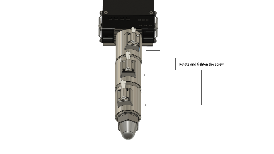
1. Before adding the felt, rotate the heater bands to an optimal position for proper wire routing.
2. Tighten the screws on the back of the band. It is wise to secure the screw with an additional nut (no locknut).
WARNING:
Do not use thermal paste between the heater bands and the barrel to ensure proper electrical connection to Protective Earth!!
![]()
-
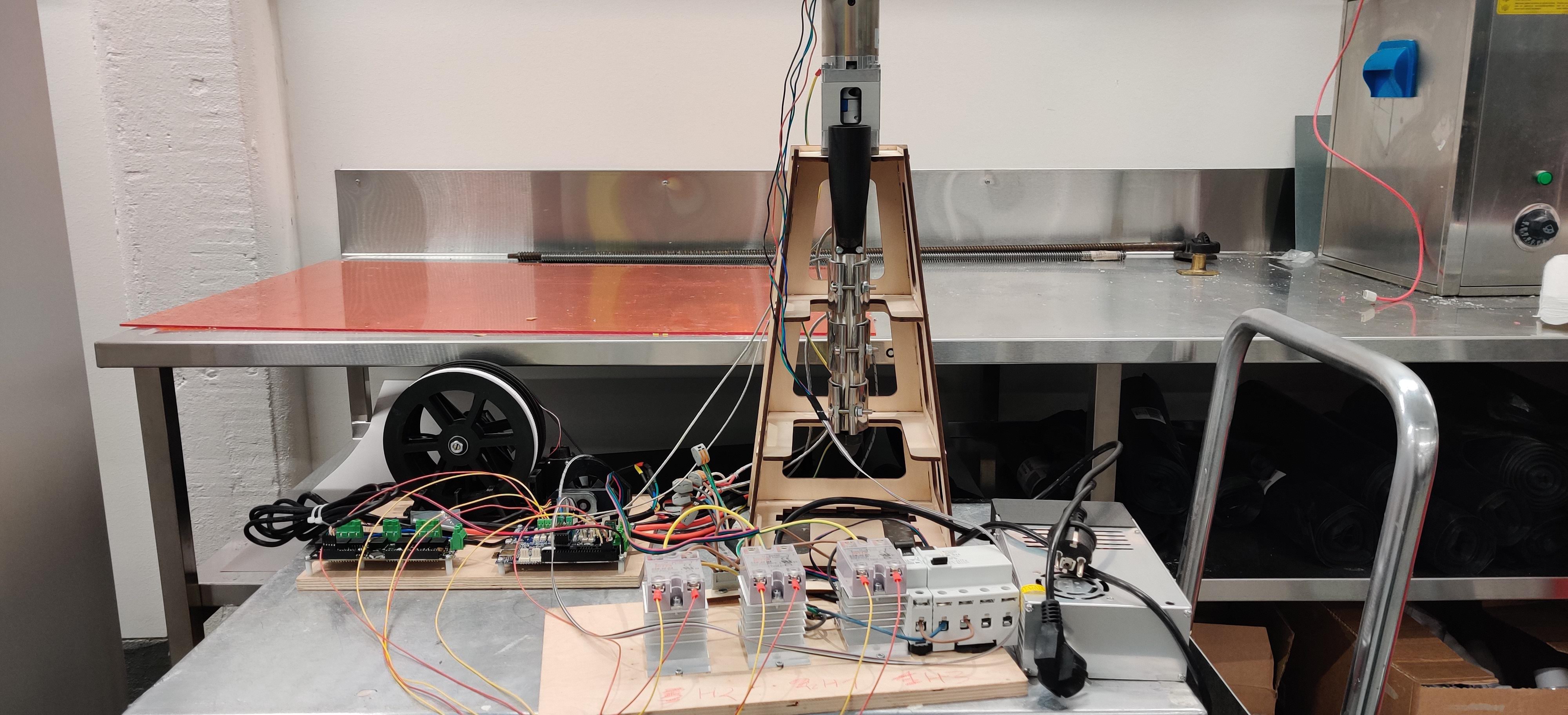
14Connecting to a Controller
The Badass Pellet Extruder can be used on different types of 3D printers or robotic arms. Therefore we cannot give you an definite answer on how to connect the extruder to an existing controller. We have been using the Duet 2 Wifi for several years now. Duet is very well documented and supported. For other than Duet controller please check that you can drive multiple stepper motors as one tool. It is necessary to drive both motor with different RPM's. And of course you should be able to add at least three temperature sensors to the controller and set them up for one single tool.
Beyond the temperature sensors in the heater bands, it is also advisable to monitor the temperature at the barrel entry in order to notice high temperature situations that might lead to premature melting or sticking of the plastic pellets. A good spot for the temperature sensor terminal is one of the screws holding the hopper to the extruder.
Depending on the size of your printer it might be worth considering the use of an external stepper driver that could be attached directly to the extruder so you won't have too long motor leads.
![]()
In order to connect the heater bands to Duet you will need to drive them by external solid-state relays. These should comply to your local requirements. These are safety related components, you should go with well known brands only and have enough current overhead as you don't want to run them near maximum limit.
Furthermore, for additional fire safety you can consider using thermal fuses which will shut off the power if the temperature should go over a given threshold.
Bloft Mk2 - 3D printer for plastic waste
An open source large format 3D-printer for plastic re-/upcycling


Discussions
Become a Hackaday.io Member
Create an account to leave a comment. Already have an account? Log In.