Open Green Energy
-
PCB Design for Transmitter and Receiver
09/12/2022 at 19:40 • 0 commentsAfter finalizing the schematic for both the Transmitter and Receiver Unit, I have designed the PCB for them.
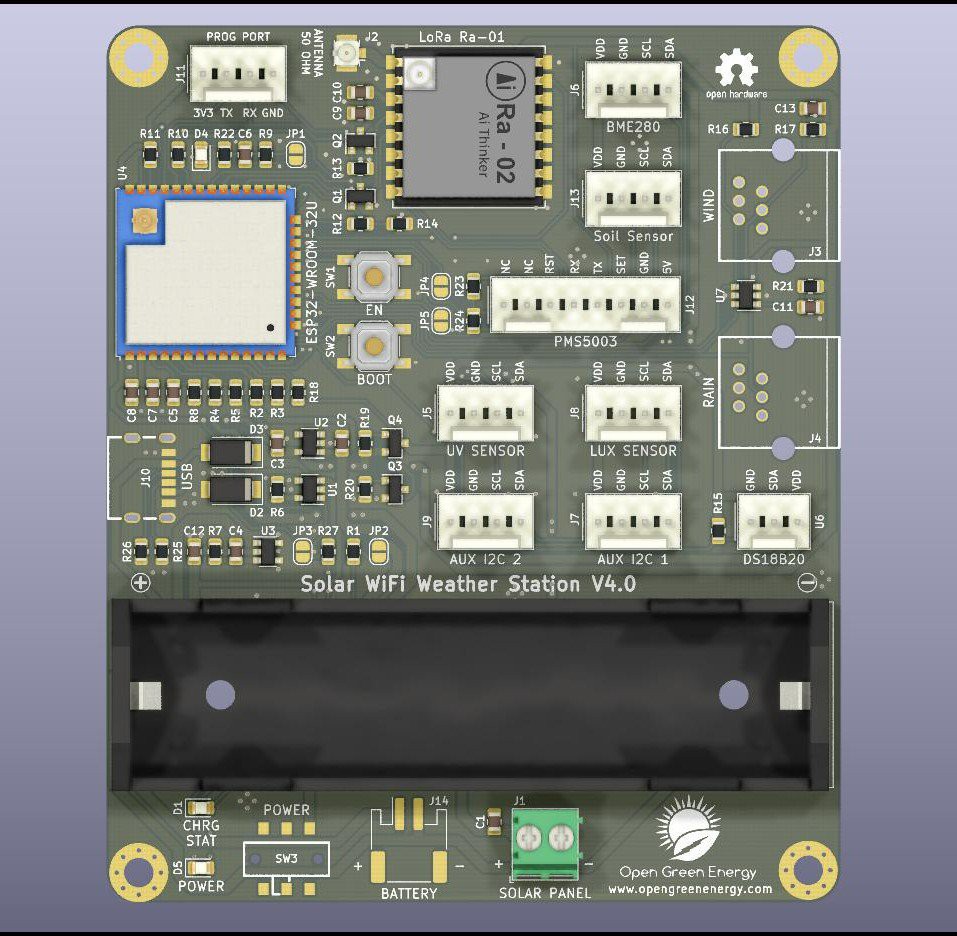
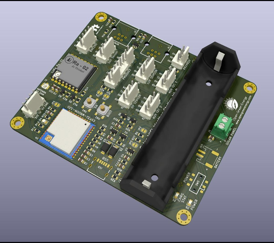
PCB design for Transmitter ( Sender Node ) :
![]()
![]()
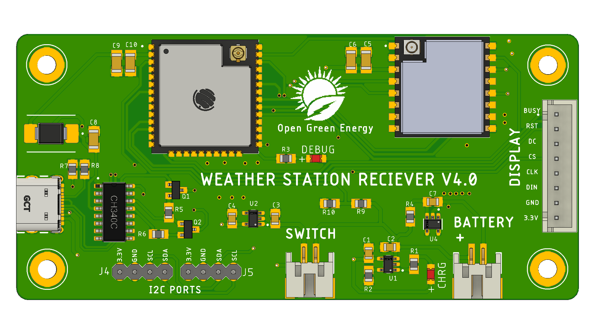
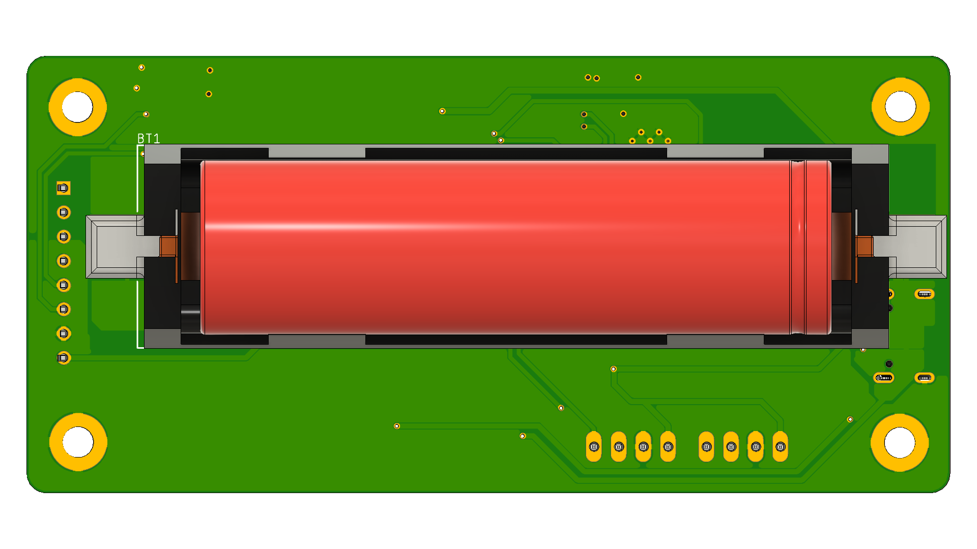
PCB for Receiver Node :
![]()
![]()
-
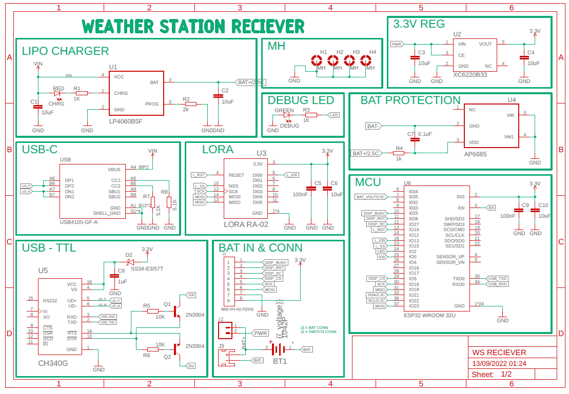
Finalizing the Receiver
09/12/2022 at 19:32 • 0 comments![]()
The receiver node is designed to receive the weather sensor data sent by the sender node from the field. Then display the received data on various platforms like ThinkSpeak, Blynk App, or on an e-paper display.
I have drawn the receiver schematic on the Autodesk eagle. The main features of the receiver units are:
1. Onboard power supply
2. Charging Circuit for 18650 battery / LiPo Battery
3. I2C headers for hookup sensors to monitor the indoor parameters
4. SPI interface port for connecting an e-paper display.
5. USB to Serial Programmer
-
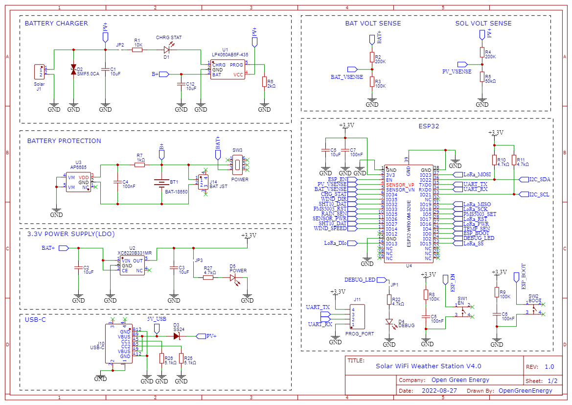
Complete Schematic Diagram
09/01/2022 at 02:46 • 0 commentsHere is the final schematic for the Weather Station V4.0. It has two sheets, the first sheet is related to the charger, power supply, and the ESP32 board. The second sheet is on the interfacing of the LoRa module with ESP32 and all the weather sensors.
Sheet-1:
![]()
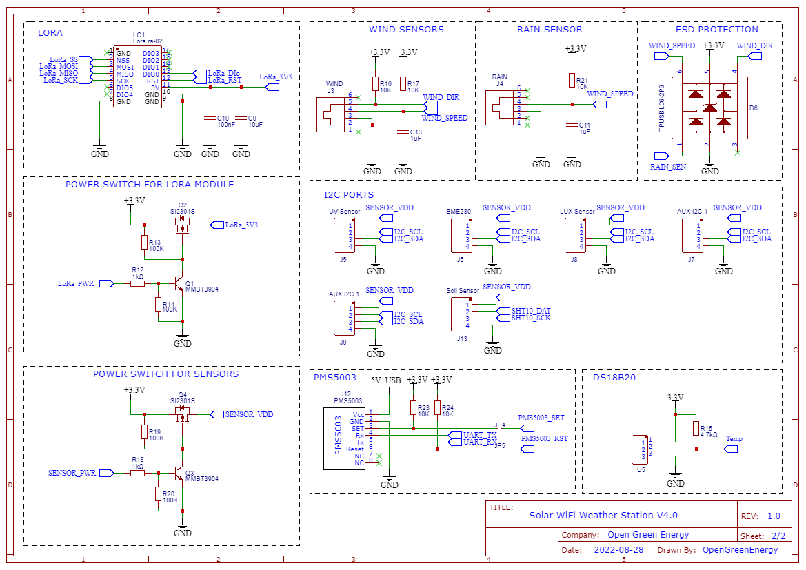
Sheet-2:
![]()
-
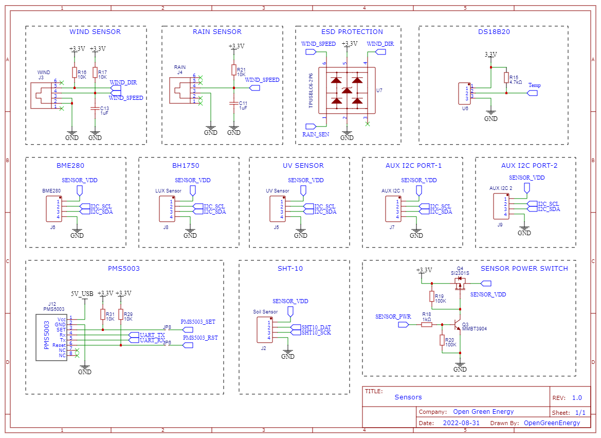
Adding Weather Sensors
08/30/2022 at 19:31 • 0 comments![]()
This Weather Station is a compact weather station that consists of several meteorological sensors that measure most of the useful weather parameters:
1. Internal Temperature (BME280)
2. Humidity (BME280)
3. Barometric Pressure (BME280)
4. External Temperature (DS18B20)
5. Wind Speed ( Sparkfun Weather Meter )
6. Wind Direction ( Sparkfun Weather Meter )
7. Rain Gauge ( Sparkfun Weather Meter )
8. UV Index ( SI1145)
9. Lux Level ( BH1750 )
10. Air Quality Sensor ( PMS5003)
Apart from the Weather Sensors, I have added an additional port for the Soil Temperature and Humidity sensor, which is useful for agriculture.
I have also added some spare I2C ports to connect sensors as per the user's preference.
ESD Protection:
As the wind and Rain sensors are exposed to the environment, an ESD protection diode ( U7 ) is used to protect the board from unwanted voltage surges.
Complete Shutdown of all the sensors:
I have added a power switch similar to the LoRa module for a complete shutdown of all the sensors. It will reduce power consumption significantly.
-
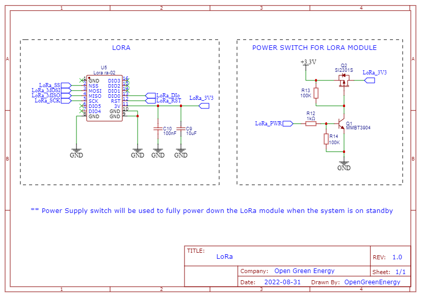
Interfacing with LoRa Module
08/30/2022 at 19:11 • 0 comments![]()
LoRa is a 'Long Range' low power wireless standard intended for providing a cellular style low data rate communications network. LoRa is ideal for providing intermittent low data rate connectivity over significant distances.
LoRa is a wireless modulation technique derived from Chirp Spread Spectrum (CSS)
technology. It encodes information on radio waves using chirp pulses - similar to the way dolphins and bats communicate! LoRa modulated transmission is robust against disturbances and can be received across great distances.
Few awesome features of LoRa communication:
- Ultra low power - LoRaWAN end devices are optimized to operate in low power mode and can last up to 10 years on a single coin cell battery.
- Long range - LoRaWAN gateways can transmit and receive signals over a distance of over 10 kilometers in rural areas and up to 3 kilometers in dense urban areas.
- Deep indoor penetration - LoRaWAN networks can provide deep indoor coverage, and easily cover multi floor buildings.
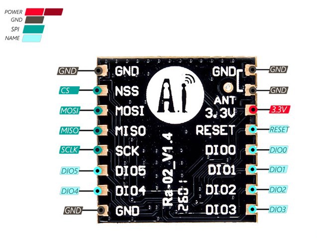
Interfacing with ESP32:
![]()
The LoRa module has been connected to ESP32 through the SPI protocol.
Deep Shutdown of LoRa:
I have added a power switch circuit by using a MOSFET ( Q2) and transistor ( Q1 )for complete shut down of the LoRa module during the sleep mode.
-
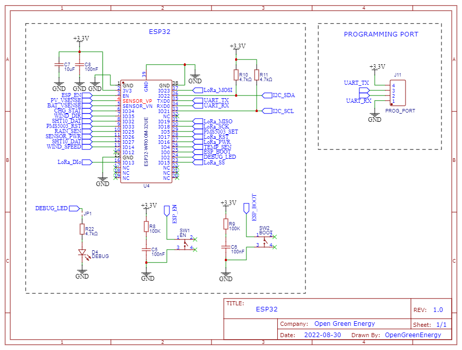
ESP32 Interfacing
08/30/2022 at 18:46 • 0 comments![]()
The main controller for this project is an ESP32-WROOM32 microcontroller. The 3.3V power supply from LDO is fed to the 3V3 pin of ESP32 with input filter capacitors C7 and C8. The two resistors R10 and R11 are pull-up resistors for the I2C bus. LED D4 with a current limiting resistor R22 is used for indicating the debugging status. A jumper JP1 is used to enable or disable the debug LED. If you need this LED, you have to short the jumper JP1.
The Program port J11 is used for connecting the board with a programmer to upload the firmware.
-
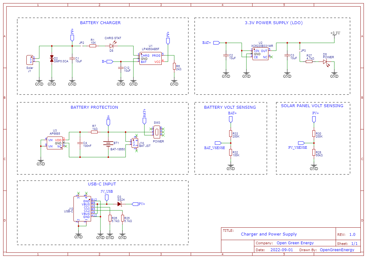
Power Supply
08/29/2022 at 19:46 • 0 comments![]()
If you are planning to install the weather station at a remote location like your farmhouse, you may not get access to the power grid to run the weather station. To run the station continuously, there must be a continuous power supply otherwise the system will not work. The best way to provide continuous power to the circuit is by using a battery. But in the case of the battery, after some days of run, its juice will run out, and it is a really difficult job to go there and charge it. So a solar charging circuit was proposed to use free energy from the sun to charge the battery and power the PCB board.
Li-Ion/LiPo Battery Charger:
The battery is charged from a Solar panel through an LP4060 charging IC. The charger circuit charges the battery by taking power generated from the solar panel. It is based on a lithium-ion battery charger IC LP4060. It is a complete constant-current/constant-voltage linear charger for a single-cell lithium-ion battery. It uses only a few external components like resistor ( R6 ) and capacitors ( C1 & C12 ). The circuit is based on the application circuit given in the datasheet.
The CHG_STAT LED ( D1 ) is used to indicate the battery charging status, it will turn off when the charging is finished. You can enable this LED by shorting the jumper JP2.
Battery Protection:
The Battery Protection Circuit provides various protections to the Li-Ion battery. The circuit is based on IC - AP6685 which contains internal power MOSFET, high-accuracy voltage detection circuits, and delay circuits. The IC has the following protections inbuilt:
1. Reverse polarity protection
2. Over Charge Protection
3. Over-Discharge Protection
4. Load short circuit protection
The circuit diagram for both the charger and protection circuits is derived from their datasheets. The datasheets are attached below.
1. LP4060
2. AP6685
USB-C Input:
USB-C port is used for faster charging of Lithium Ion Battery. The 18650 battery outputs 4.2V when fully charged. The resistors R25 and R26 are used as pull-down resistors.
3.3V Power Supply:
The operating voltage of the ESP32 and LoRa module is 3.3V whereas the fully charged battery voltage is 4.2V. So we have to step down the battery voltage from 4.2V to 3.3V, which can easily be done by a linear voltage regulator but unfortunately, it is not at all recommended for this project. Because all the linear regulators require an input voltage at least some minimum amount higher than the desired output voltage. That minimum amount is called the dropout voltage. Due to this reason when battery voltage drops to around 3.7V, the linear voltage regulator will not be able to maintain the required voltage ( 3.3V ).
The solution to the above problem is to use a low-dropout or LDO regulator. A low-dropout or LDO regulator is a DC linear regulator which can regulate the output voltage even when the supply voltage is very close to the output voltage. Here we will use an XC6220B331MR LDO for efficiently powering the Circuit.
The capacitors ( C2 and C3 ) are connected to the input and output of the LDO to smooth the voltage peaks.
Solar Panel and Battery Voltage Sensing:
The max allowed voltage input to the ADC pin of the ESP32 is around 3.2~3.3V but a fully charged 18650 battery and solar panel voltage are in the range of 4 - 6V. So to measure these voltages we have to step down the voltages by using voltage divider networks.
The battery voltage is sensed by the voltage divider consisting of R2 and R3. Similarly, the solar panel voltage is sensed by the voltage divider consisting of R4 and R5
The voltage divider formula is as follows:
Vbat_sense = (Vbat*R3)/(R2+R3)
Vsol_sense = (Vsol*R5)/(R4+R5)
Solar Powered WiFi Weather Station V4.0
An affordable Open Source Weather Station for Everyone