Peter Lyons
-
Pinky build and 2nd PCB
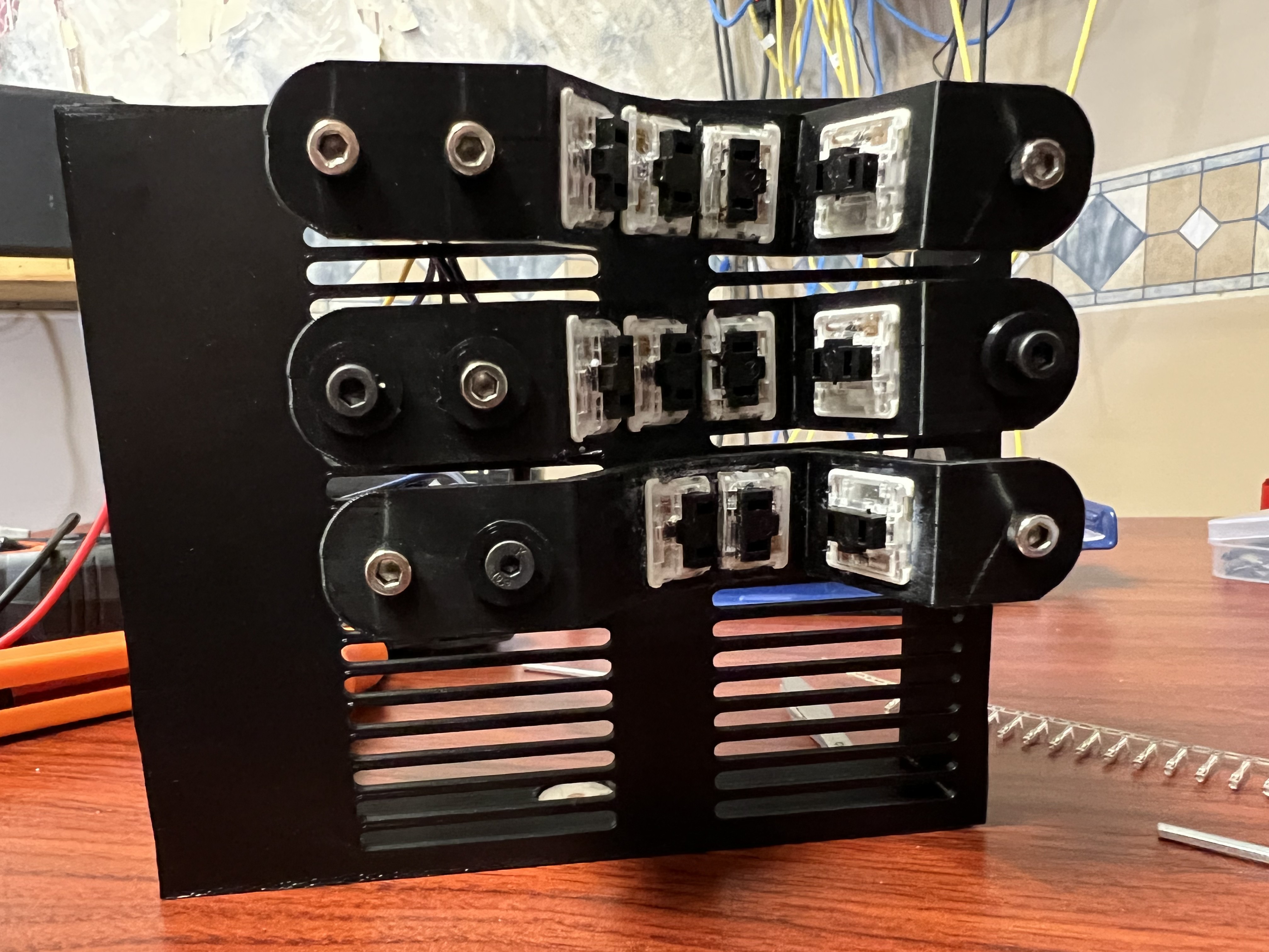
09/11/2022 at 23:22 • 0 commentsToday I wired up one middle finger 1x3 keywell column and one pinky 1x2. So I've got a left hand except for the thumb. Crimping DuPont connections is very fiddly and I don't really have a good technique for it, but I mostly manage to hack my way through it.
![]()
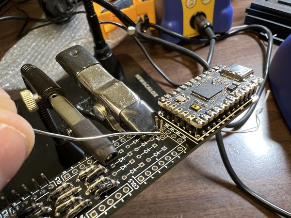
Since I soldered the pin headers onto the first PCB wrong and the excess solder on the pins is interfering with the DuPont connections connecting fully, I decided to build out another PCB. The pin headers went in properly this time and I did all the diodes and socketed the MCU. However, at the end of the day after I moved the MCU from the 1st PCB to the 2nd PCB it was kind of D.O.A. so I decided to call it a day and try again next session. Not sure if the socketing diode legs are screwed up or something is shorted now or what but it won't type anything and won't reset and won't flash anymore.
The DAP Rapid Fuse adhesive I'm using to hold the switches into the keywells is creating some ugly white residue as it dries. I put it on very precisely with the brush applicator but it shows up dried well aware from that so my current theory is it's actually leeching into the PLA itself and working its way through to the nearest surface. Some of it came off OK with a small file but it's a bummer.
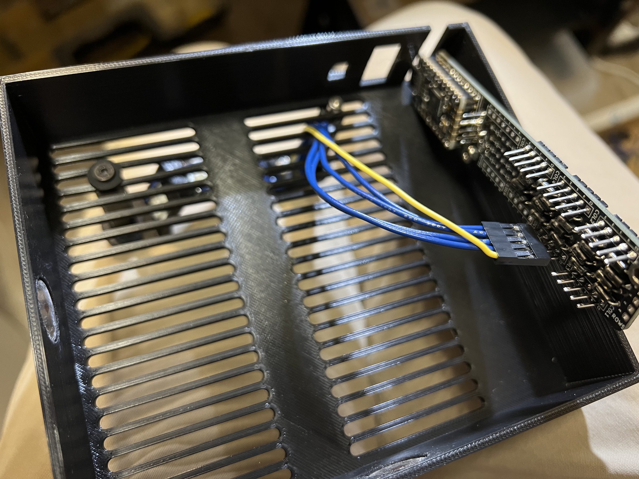
Overall the strain relief is working nicely and having all the row interconnects handled on the PCB instead of hand wiring really does clean things up a lot.
So I've got 4 keywells fully built. 2 PCBs mostly built, and one thumb cluster glued up. Hopefully the MCU misbehaving will be easily solved at the start of next session with a clear head.
![]()
-
Wiring middle column
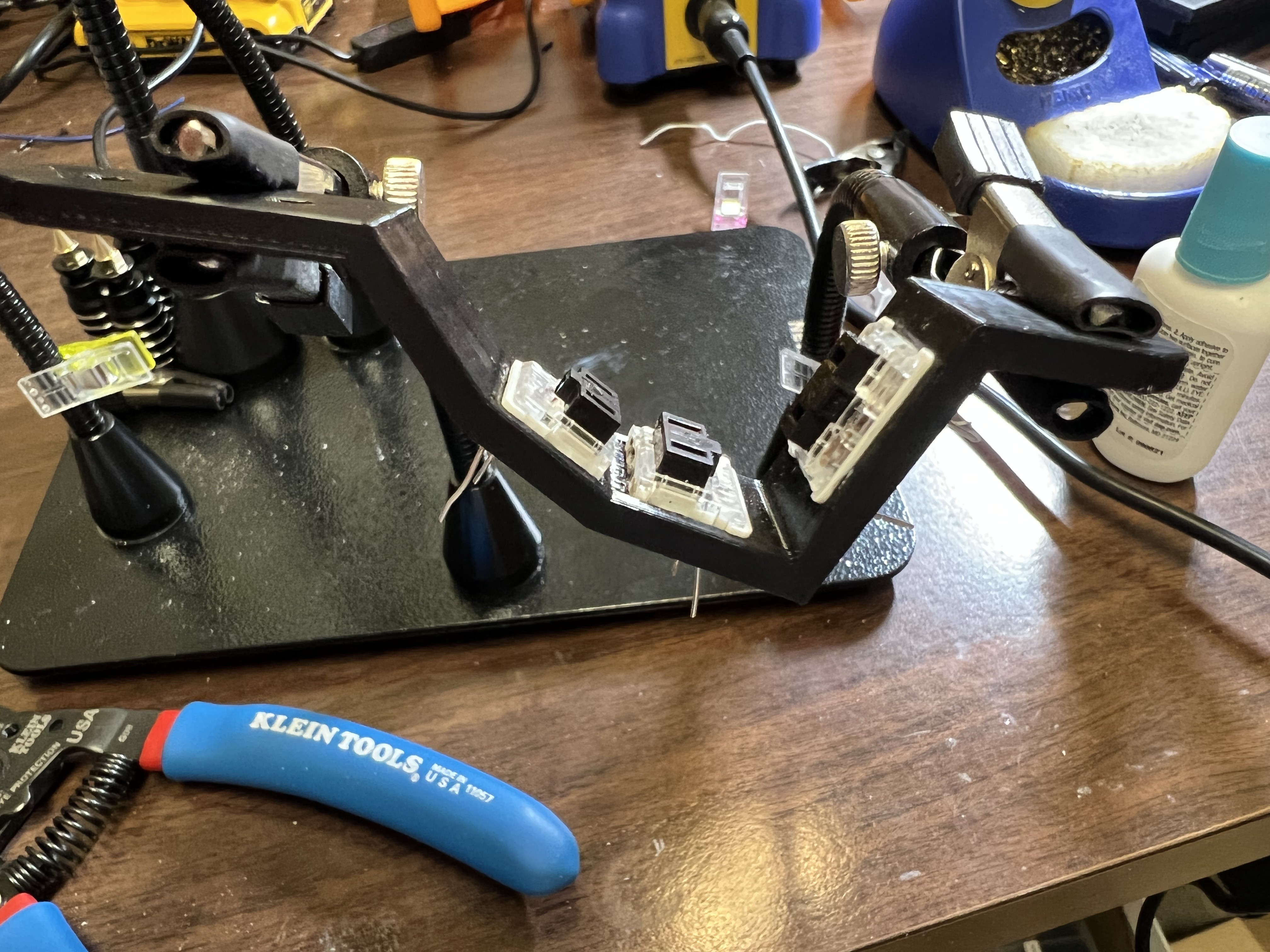
09/11/2022 at 04:17 • 0 commentsI chopped enough choc mini switches to finish one hand.
I soldered short lengths of wire to each switch pin to make wiring easier after they are glued into the keywell and reduce the chances of melting the PLA by accident.![]()
This is a 1x3 column for the middle finger which is why the top row space is blank.
-
Wiring up second column
09/10/2022 at 14:37 • 0 commentsI wired up the switches for a second 1x4 keywell column yesterday. I approached the different wire lengths by just soldering the loose ends at whatever their current length was. This messed up the arrangement and I think the only way to fix it is to remove the dupont connector, cut all the wires so they end at the same spot, recrimp the dupont ends and re-attach the dupont housing. I think trying to pre-build these wires while on vacation didn't quite work out. But that should be pretty straight forward.
I've also been frustrated with so little clearance between the switch pin and the printed housing, so as I proceed I plan to solder a longer bit of wire to the switch pins BEFORE I glue the switches in place so the hand wiring should be less fiddly and tedious.
-
Keywell Hand Wiring
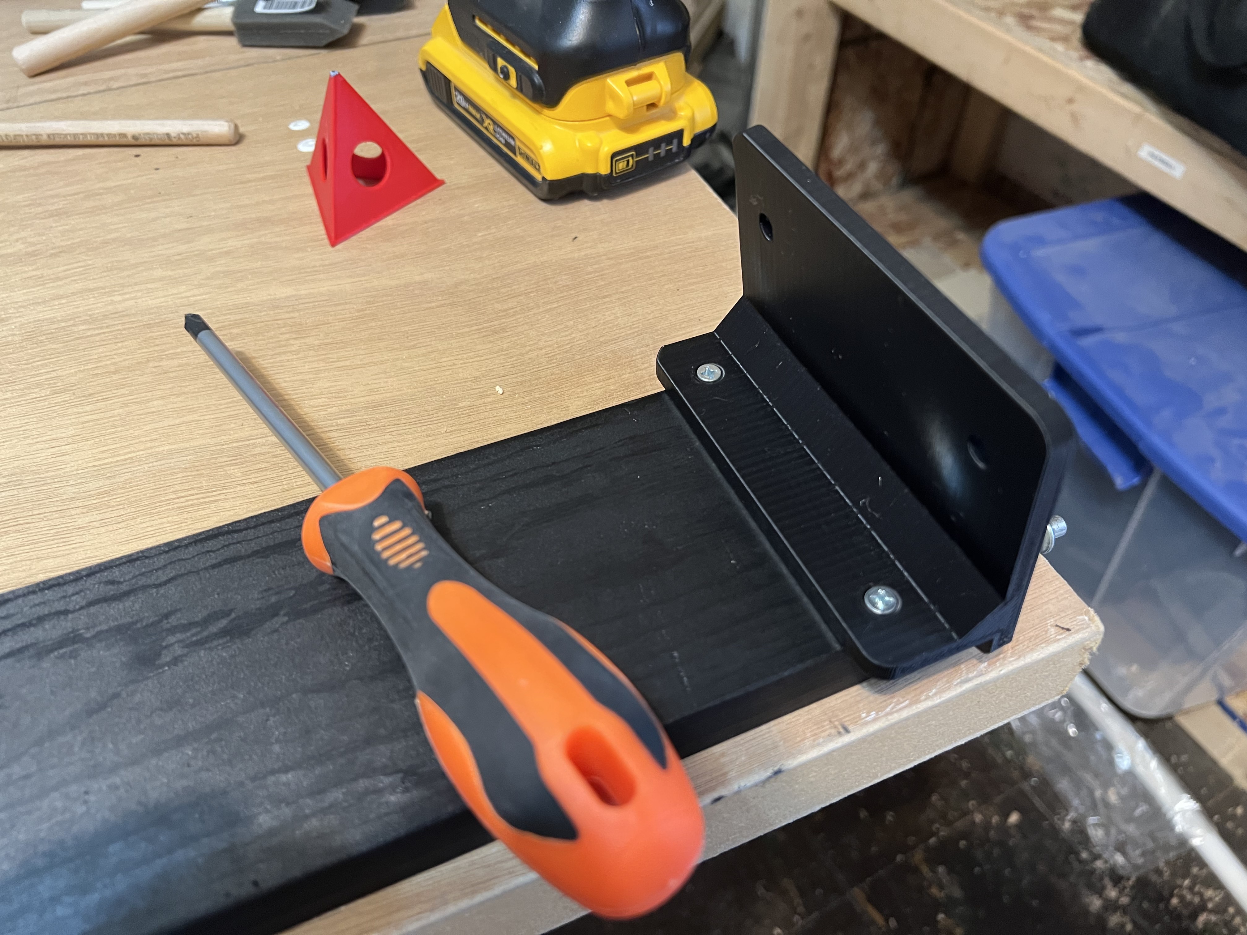
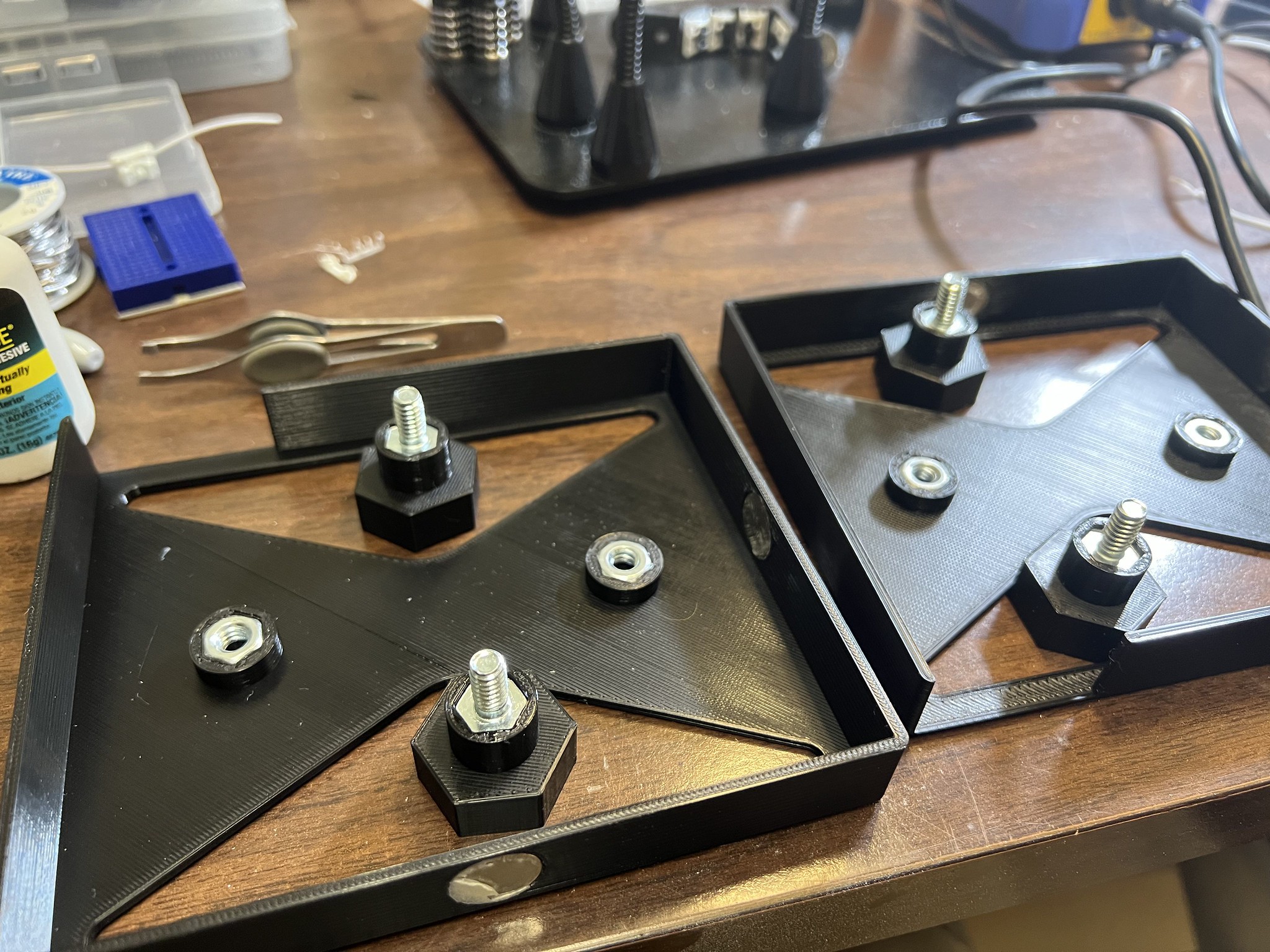
09/05/2022 at 21:11 • 0 commentsToday the paint on the base board was dry so I was able to drill pilot holes and screw the tenting plates to the base.
![]()
I glued the captured hex nuts and bolts into place for the mounting hardware.
![]()
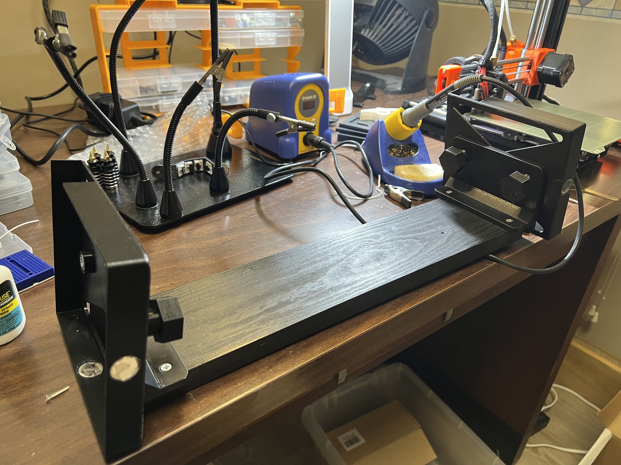
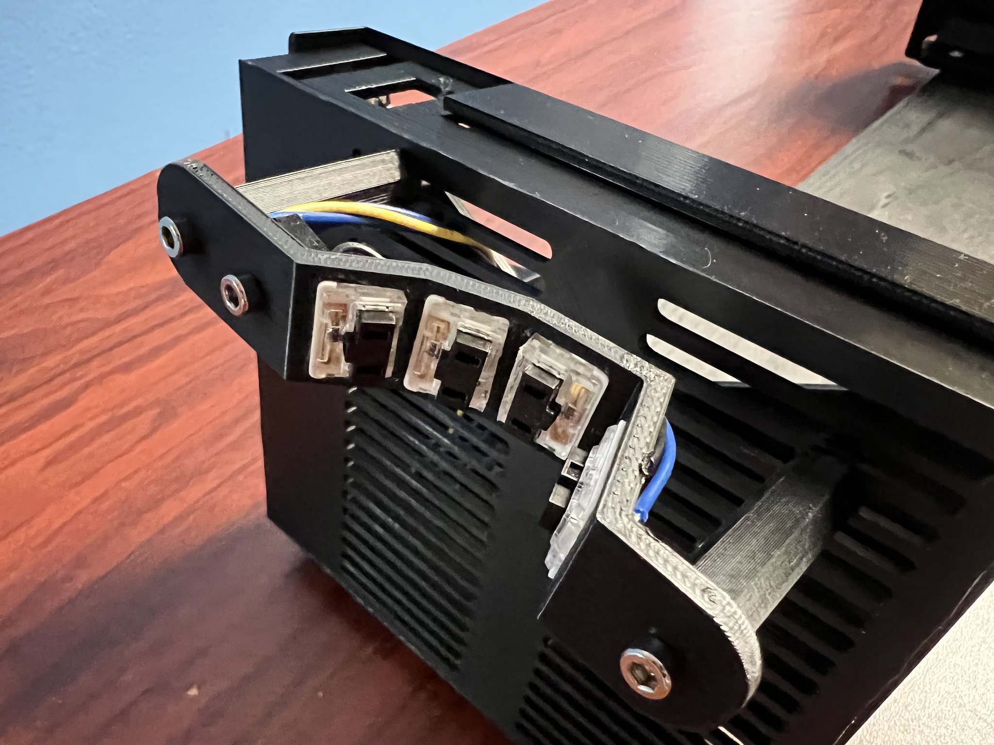
Here's the cross bar, tents, and bottom cases all assembled
![]()
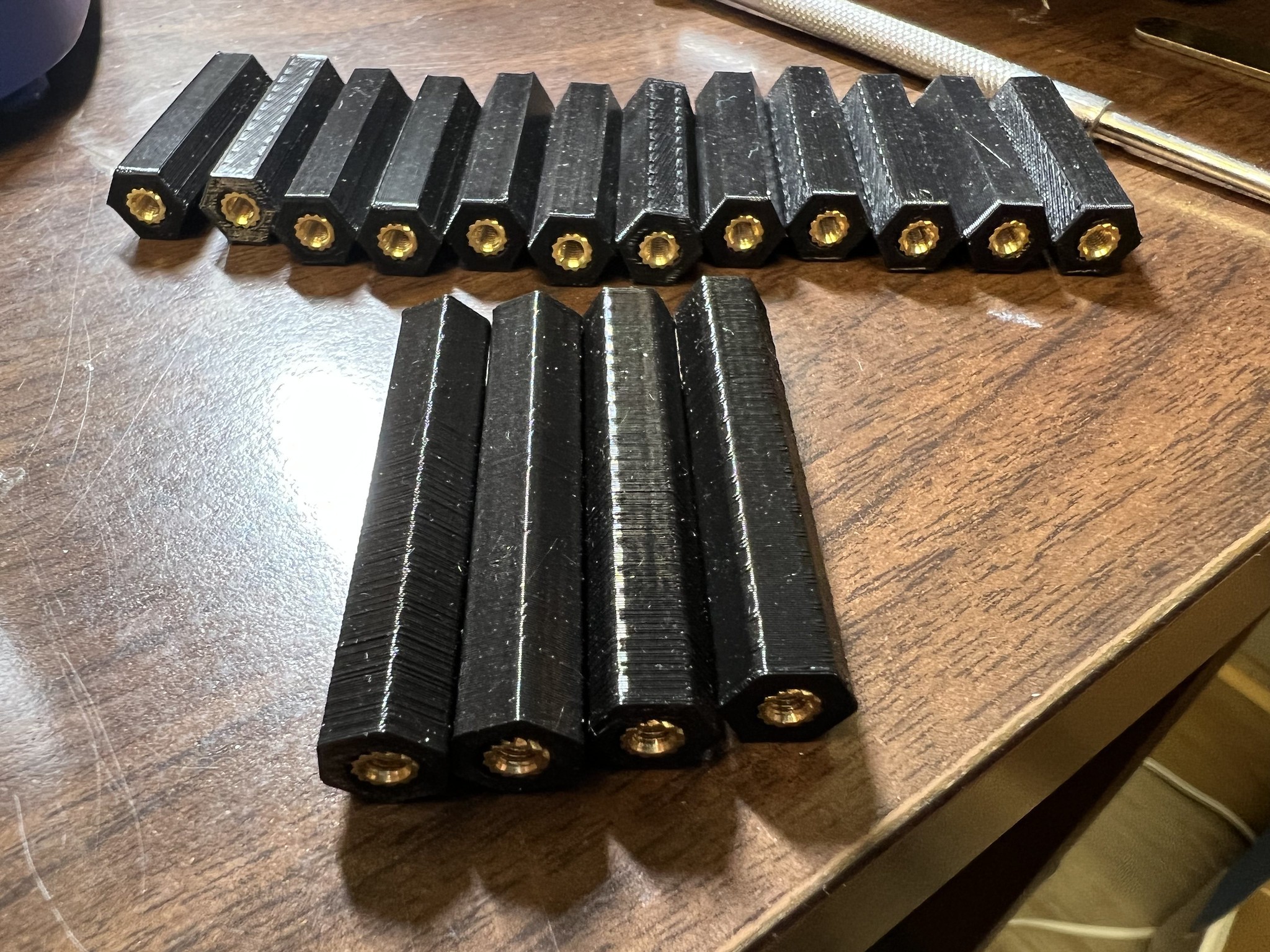
I installed all the M3 threaded inserts into the keywell standoffs.
![]()
I also put the threaded inserts into the PCB standoffs and test fit the PCB. That revealed that I hadn't accounted for socketing the MCU in my dimensions so the whole for the USB-C connector doesn't at the moment line up. There's a number of mistakes like that which may necessitate reprinting a bunch of parts, or at the very least some cutting/sawing which is always disappointing.
![]()
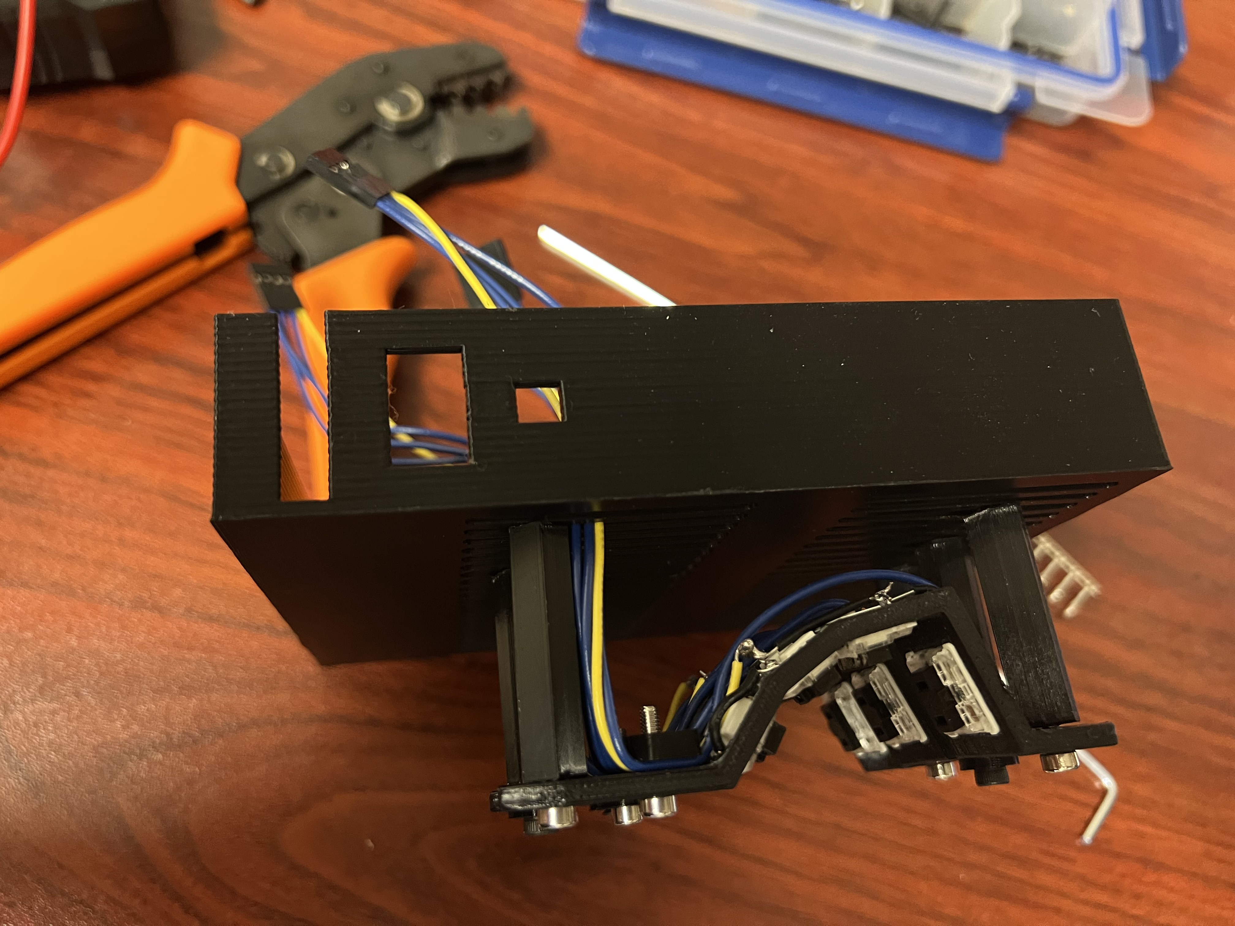
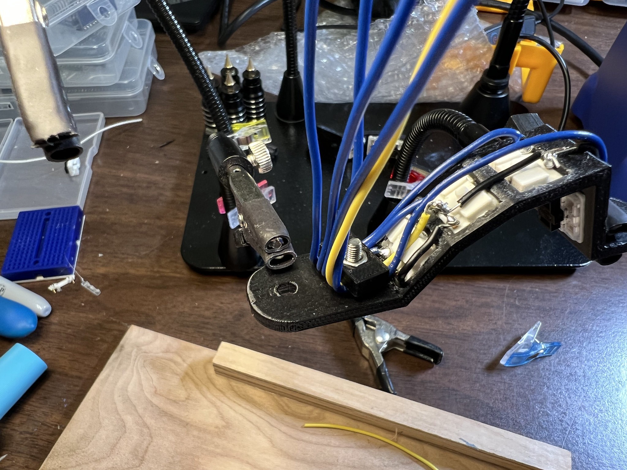
The main accomplishment today was I did the hand wiring for a single column. It's extra fiddly because the chopped chocs have almost no clearance between the switch pin and the housing, and also the pins do not protrude very far at all beyond the keywell. It's fiddly, but I got it all done.
New to this design is a very basic strain relief that works by clamping down on the wires between the keywell and a little clip. Thus any pulling force is handled there and the solder joints are spared. Despite being very basic, it does seem effective.
![]()
The custom made cables ending in DuPont connectors I assembled way back in July on some rainy days during family vacation. I estimated how long they needed to be and at least in this case it's like 1 or 2 inches short. I think I might still be able to salvage this but we'll see.
![]()
I got a new special debug/test firmware flashed for this which makes it very obvious which keys are which as well as left/right stuff. At this point I have one working key column. The choc mini blacks are silent which is great and feel good but I won't know for sure how they are until I have a complete working keyboard.
![]()
-
PCB and keywell build out
09/04/2022 at 16:04 • 0 commentsToday I'm moving forward with assembly now that I have the custom PCBs in hand and have already 3D printed a full set of parts.
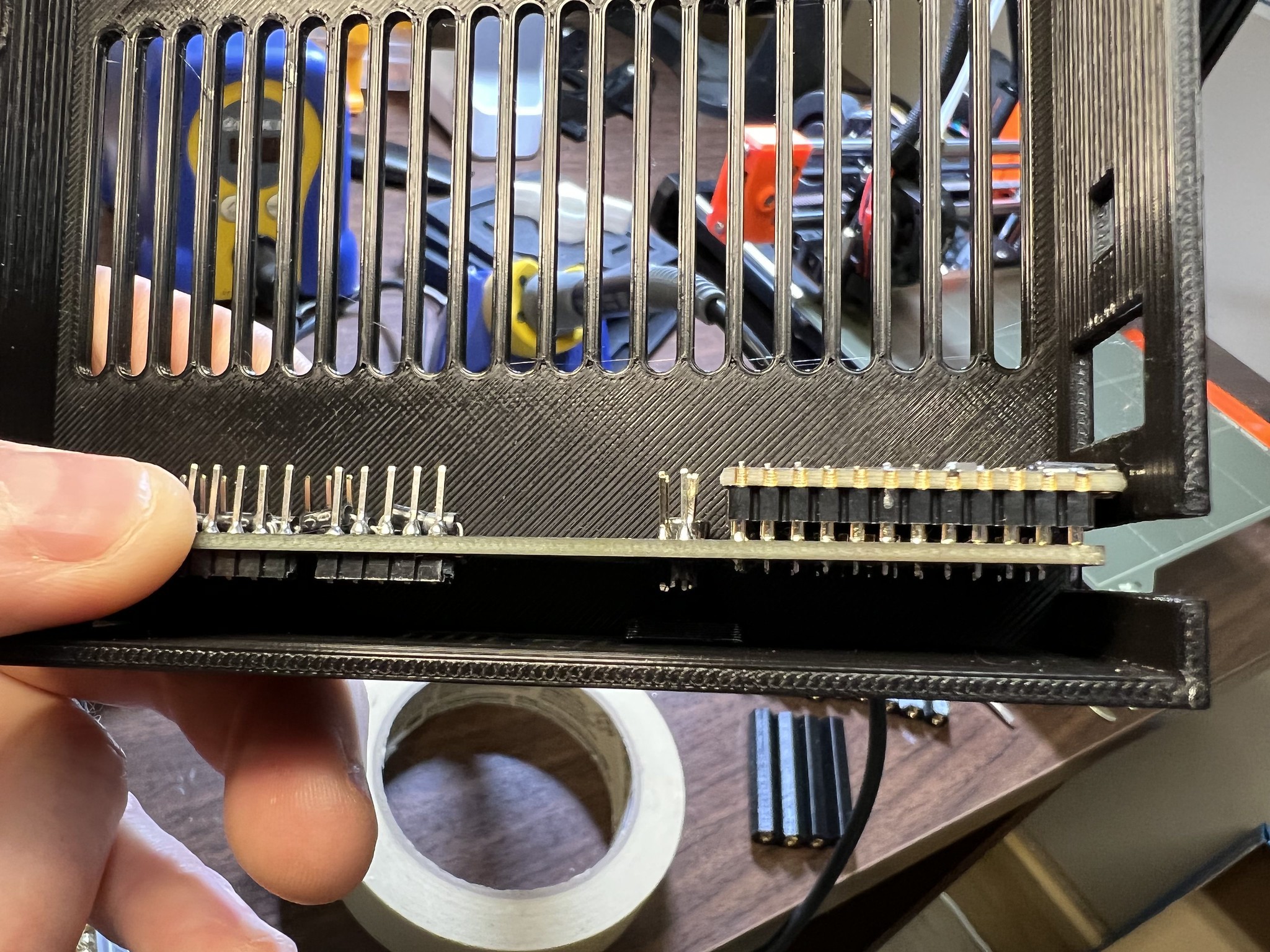
I soldered all of the pin header sets onto the PCB. These are now ready to accept DuPont connections running wires out to each key column (finger)
![]()
I later realized I should have done that 4-pin one closer to the MCU first.
I'm ready to glue switches into the keywells, but before I can do that I need to "chop" the Kailh Choc Mini switches to be even smaller footprint. It requires a steady hand and high accuracy but it's otherwise a controlled process and you get a cleaner cut. My approach is to slice through them with a circular cutting bit on a rotary tool. This can be done with a pair of flush cutters but it's a bit dodgy. Each choc switch has about 1/3 of its size allocated to housing and wiring for an LED. We don't need this and it takes up space, so we slice it off.
Once I have a few chopped chocs ready, I'll glue them into the keywells with some DAP rapid fuse with the brush applicator.
I was able to get 2 1x4 keywells chopped and glued today. I also glued the magnets into the case that snap the case top and bottom together. Glue is still a very messy business for me. There are ways the CAD for the magnets could be done to better limit glue to only below a magnet and not making a mess everywhere, but in this spot I've just got circular holes for the magnets and it'll look a bit messy.
I'm now headed to the wood shop to try to find a suitable scrap to cut, sand, and paint for the center divider/base.
Squeezebox Keyboard v2209
Iterating on the Squeezebox scooped split ergonomic keyboard. This version features a PCB instead of full hand wiring and choc mini switches