flamefire
-
Review - PCB's sponsored by PCBWAY
12/26/2022 at 10:28 • 0 commentsPCBWay reached out to me through hackaday, and they offered to sponsor my PCB's for my project! In return they wanted a few words on the quality and service they offer. PCBWay even sponsored the delivery costs which was really awesome. Making projects as an student can be quite expensive, so i humbly accept their offer, and the following is my experience with PCBWays service and quality.
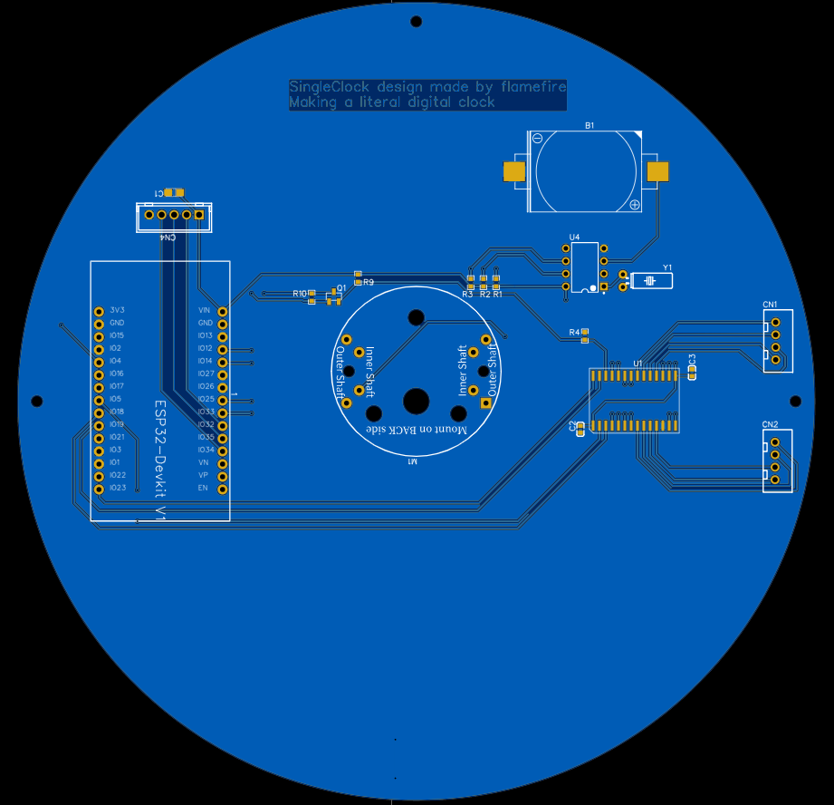
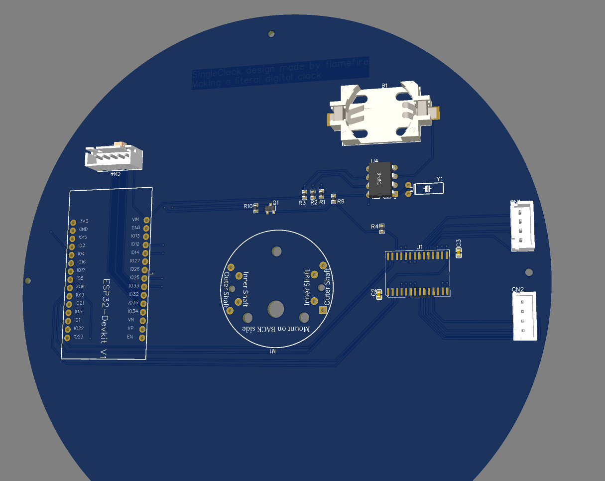
My design of the PCB made with the EasyEDA software. This is my first time designing a PCB, so dont go hatin', I have made a mistake in the routing from analog sensors to digital ports on the MCU and i have to modify my design files. Otherwise anyone would be able to download the design files and make their own PCB order if they choose to make this project.
Topside:
![]()
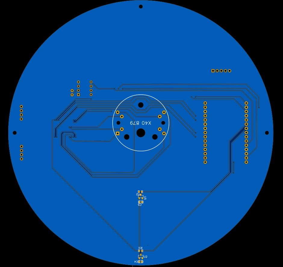
Buttomside:
![]()
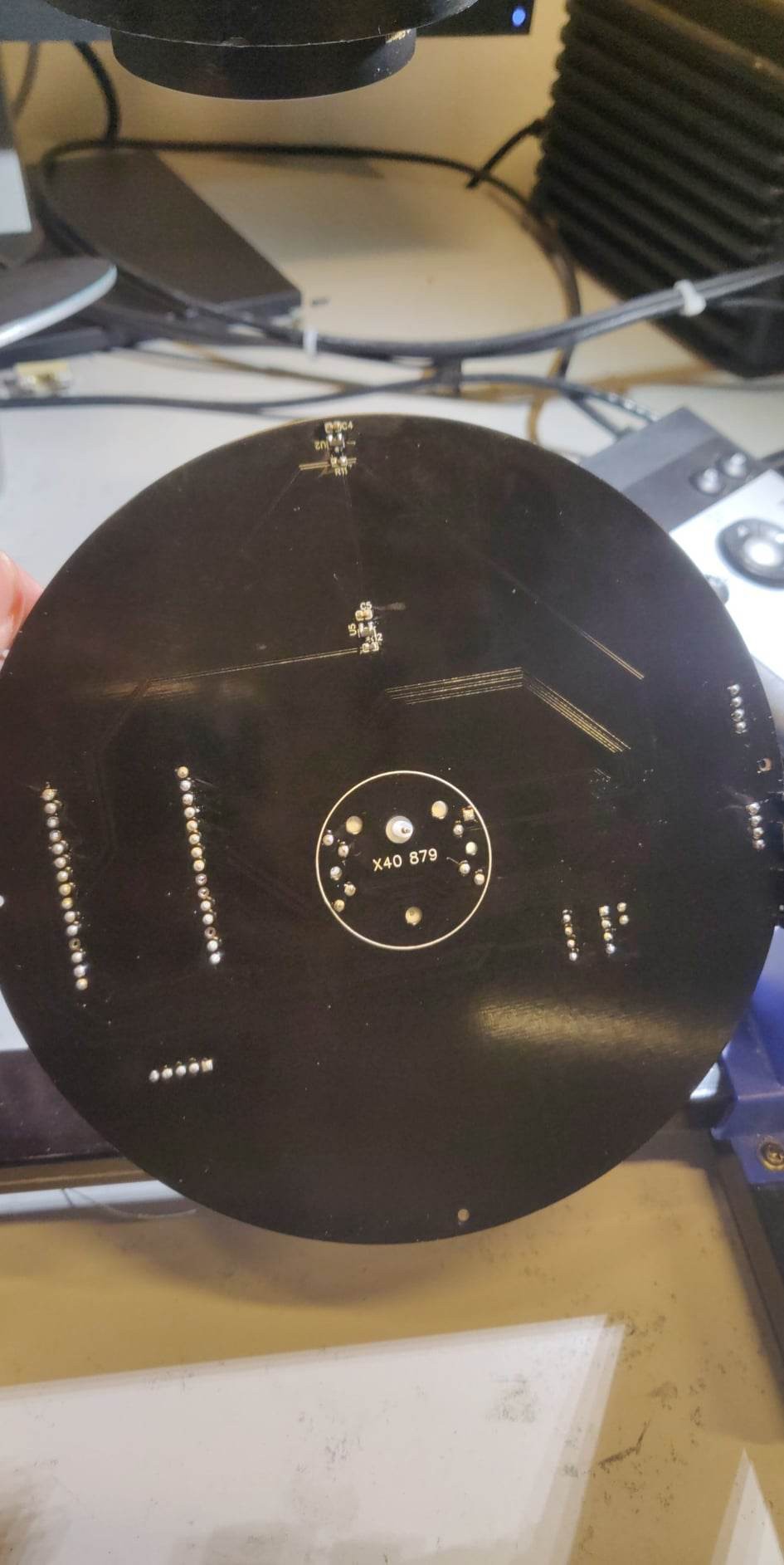
Once you have the GERBER files its very easy to order PCB's through their website. I choose to make the PCB's black, and i must say they look very cool!
![]()
Once you have ordered PCB's they will check your design, before production. I made an error in quantity, and i wrote to customer service. In no time customer service fixed the issue with no problems. Its also possible to change the GERBER files before production, just write to customer service and they will fix your problems.
If i remember correctly i choose a delivery option to 15 days so that the PCB's would arrive before christmas. They arrived after 12 days and was nicely protected.
Im no expert, but the quality of the PCB's feels very professional. I have checked the routing connections and they all have a solid connections. It was also very nice to solder the pads.
In conclusion i would recommend PCBWay, its easy to order PCB's and the quality is very high.
-
23/12 - 2022 - The assembly and project (done)
12/23/2022 at 15:56 • 0 commentsThe Result
So lets start with the finished result. What went good and what went not so good.
It can be seen in the video that the pointers is kind of slacking. They actually weigh to much! F me. That means that the whole system with magnets and hall effect sensor are not the solution to the homing system is probably not what i want.
The video is a test of the PCBs do please see the review of the PCB's.![]()
This is the final look of the digital analog clock, to fix the weight of the pointers, i made them very thin, and removed the magnet ofcourse. Maybe some fine tuning could be done about the weight of the magnet and pointers to make it work, yet to be tested.
THE BUILD
Lets talk about what i did to build it.
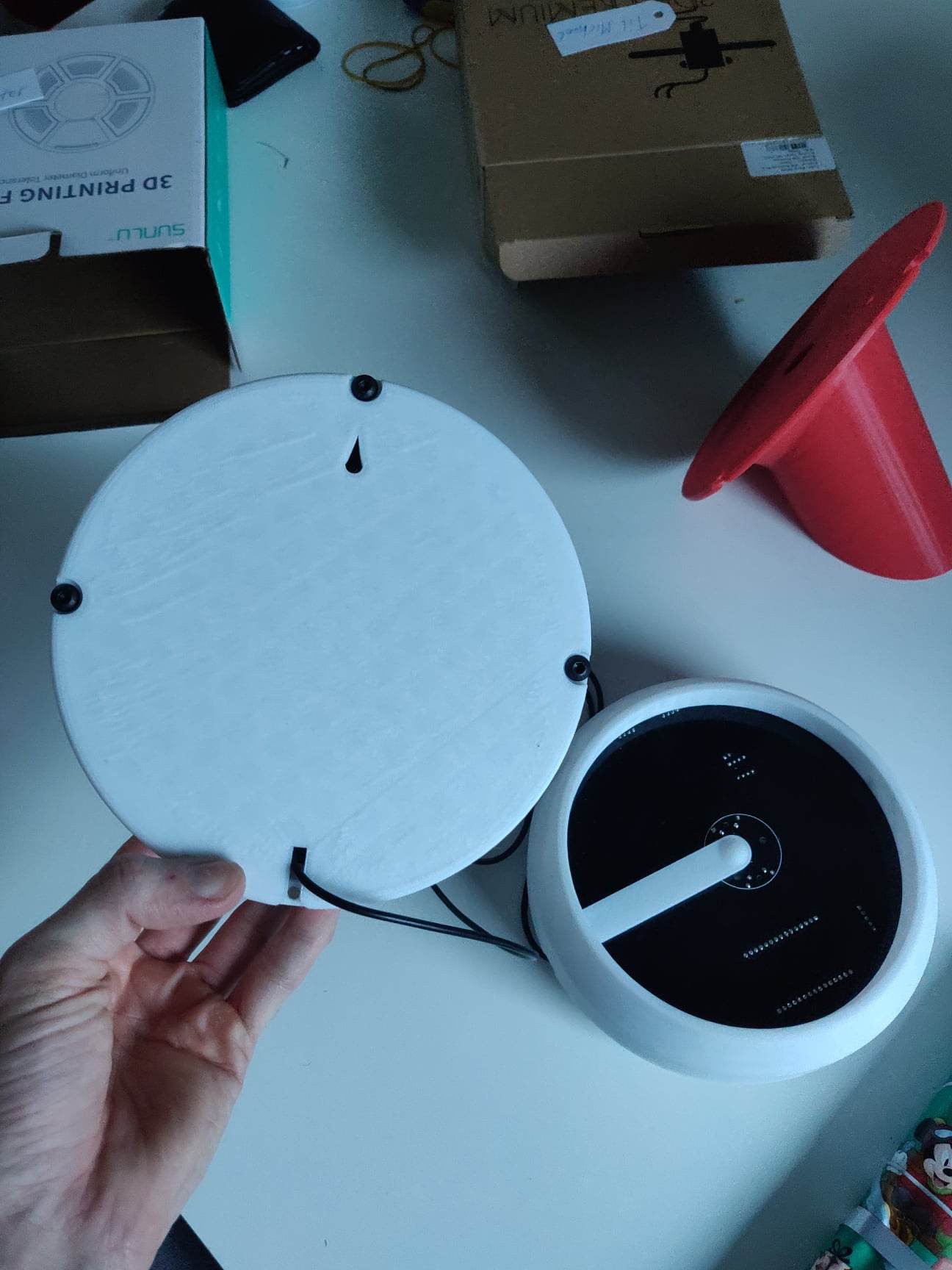
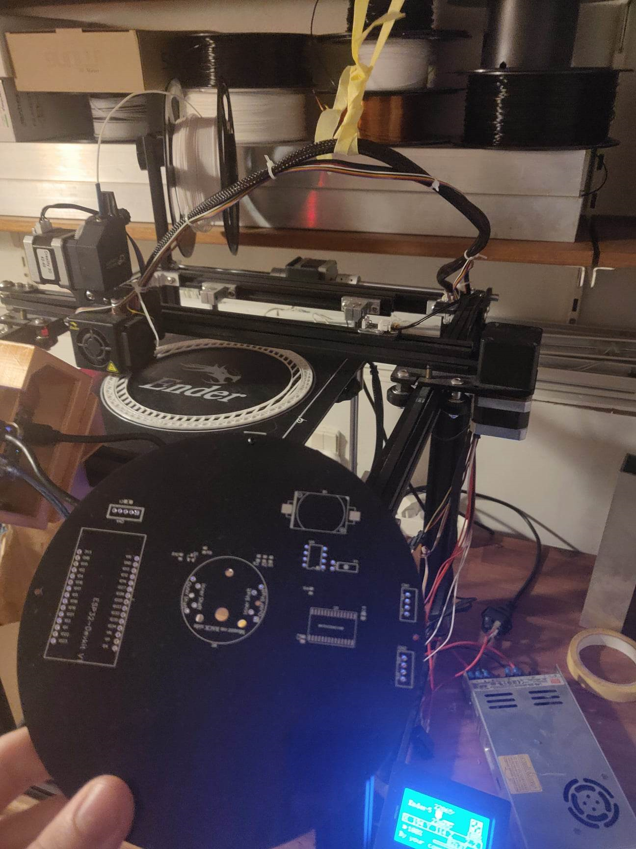
3D printer
I 3D printed the whole casing on my ender5 3D printer. A lot of fine tuning was done, to make it fit together, and remember all 3D printers are different. For an example the holes for the M5 and M2 screws had to be very accurate for it to fit, the print could otherwise crack. Speaking from experience!
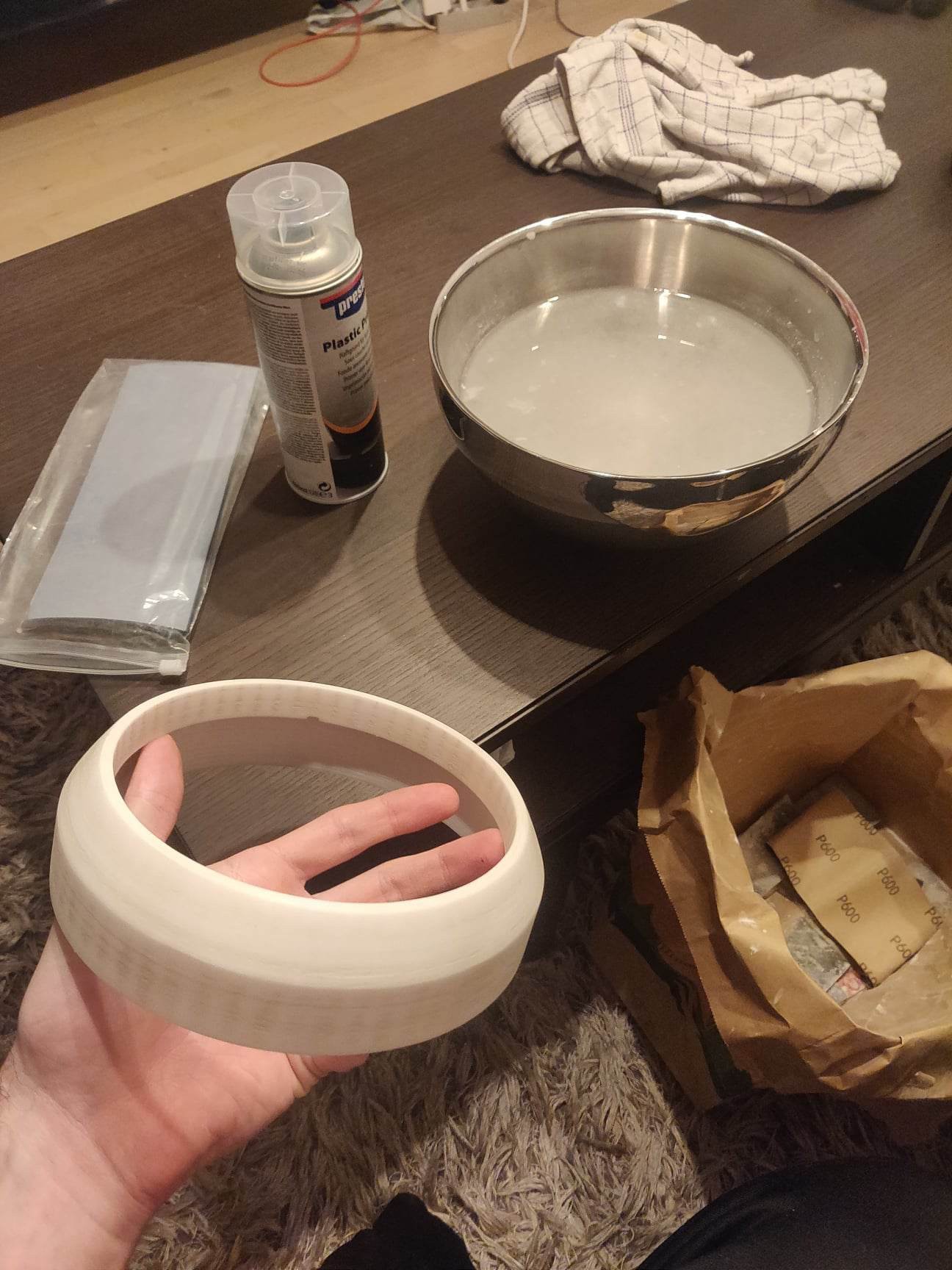
To make it look more like an product, than homebrew i tried different sanding and smoothing techniques.
![]()
![]()
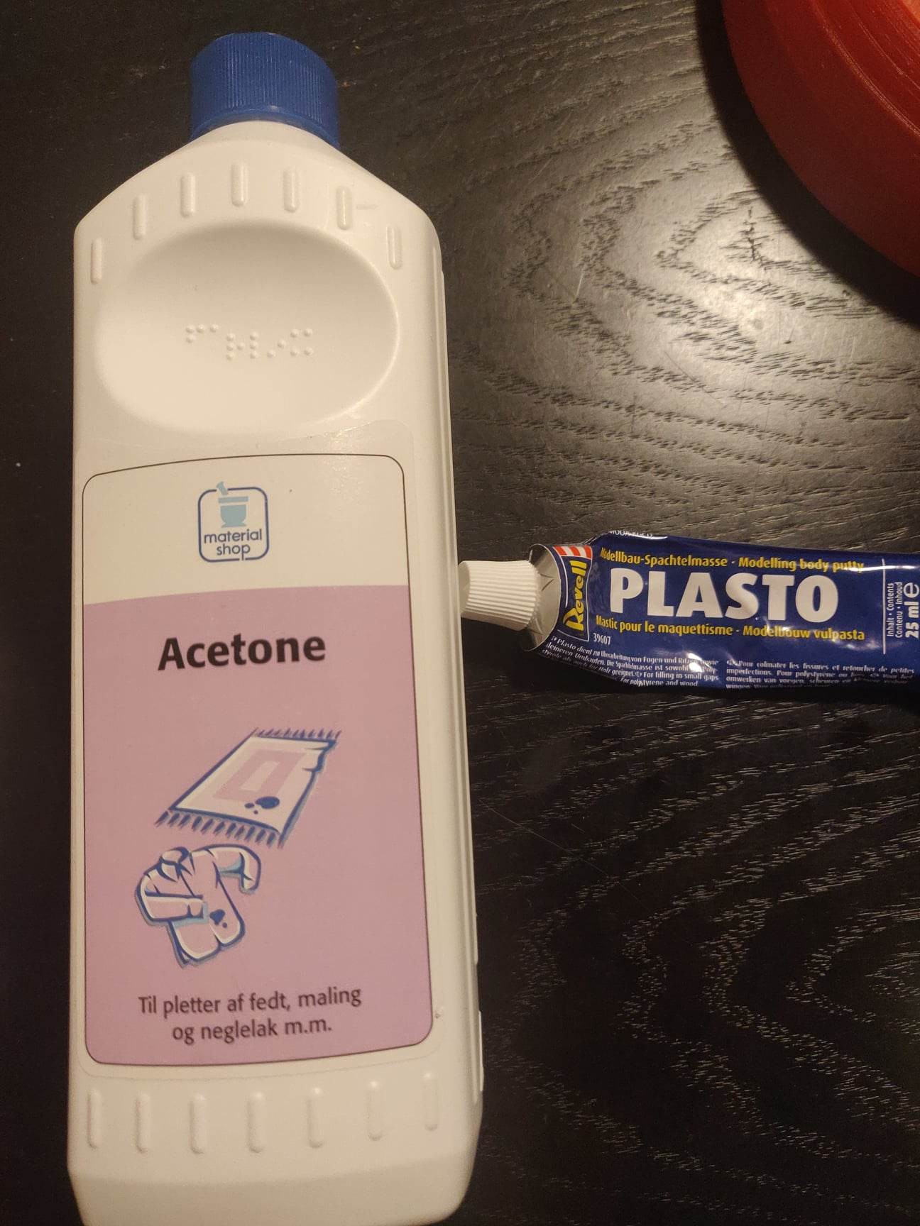
1. I tried an mixture of acetone and putty, as i had seen in a guide. I feel like the result could be the best with this solution. However a lot of time is required. First you sand the 3D print down with very rough sandpaper. You then mix the acetone(very little) and putty then paint it on the 3D print and sand it down again, with more fine sandpaper. Keep sanding it down until smoothness is achieved. Then lastly paint it your favorite color and keep painting it until the putty cant be seen anymore. This was hard for me because it was painted white.
2. A more simple solution is to apply filler spray and sand it down, keep repeating and lastly paint it.
I found that this simple solution gave a better result.
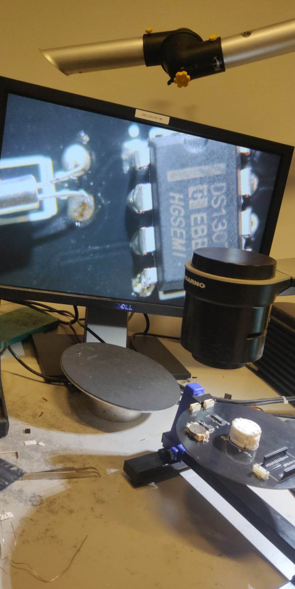
The PCB build
If you have zero experience with soldering, i would watch a video first. I am definely not good at this, and this is my first time soldering such small components. Fortunately my school has great gear for soldering.
![]()
There is a few errors in the PCB unfortunaly. The hall effect sensors are setup to non analog pins on the ESP32. And since the hall effect sensors are analog, this was not working as intended. This is unfortunate but as said before, the whole homing system is not working because the pointers would weigh to much.
Instead you set the pointers at 6 O'clock as precise as one can be, and turn on the system. As also can be seen in the video.
-
07/12/2022 - PCB's are here
12/07/2022 at 15:32 • 0 commentsThe PCB's have arrived very quick, delivery was only 7 days. So far I'm very pleased with it, a more thorough review will be coming shortly. I'm also 3D printing a test case.
-
11/30/2022 - 3D printer design
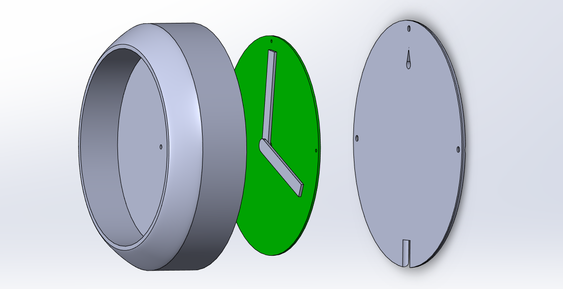
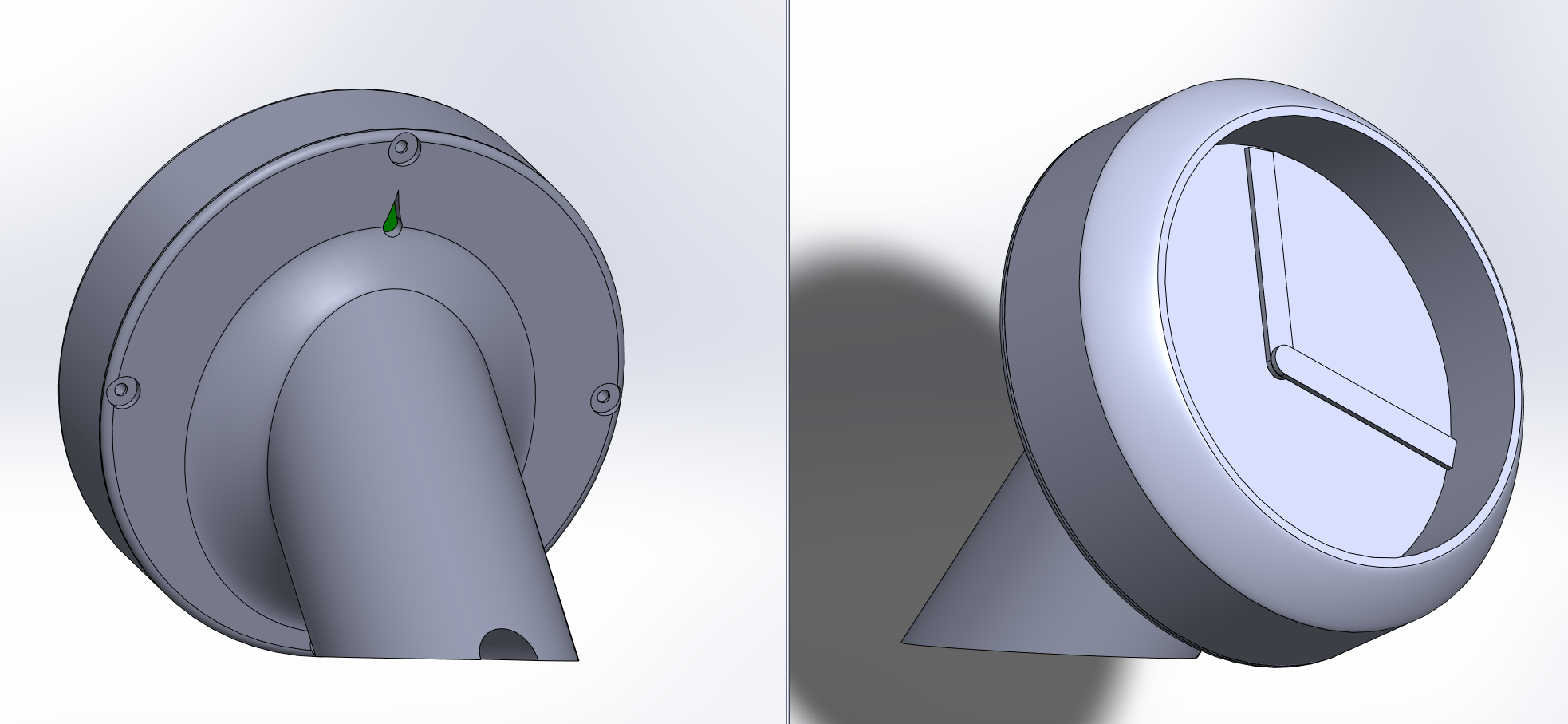
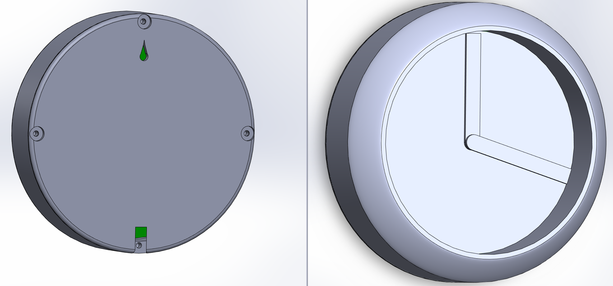
11/30/2022 at 03:03 • 0 commentsOoooh finally! My favorite part is designing the 3D model. I have used Solidworks. The Clock will be able to be setup on the wall, however I have also made a version meant for the desk.
![]()
These designs are almost done. Although I'm concerned with the hour and minute pointers being to close to the backside. The motor leaves very little space to be playing with. With the PCB at 1.6mm and the backside at 1.4mm thickness, and the space between PCB and backside, there will probably be 0.5mm. That leaves 0.5mm for the innermost pointer to the backside. Conclusion ... I will fix this problem somehow. I also need 3 buttons on the back
-
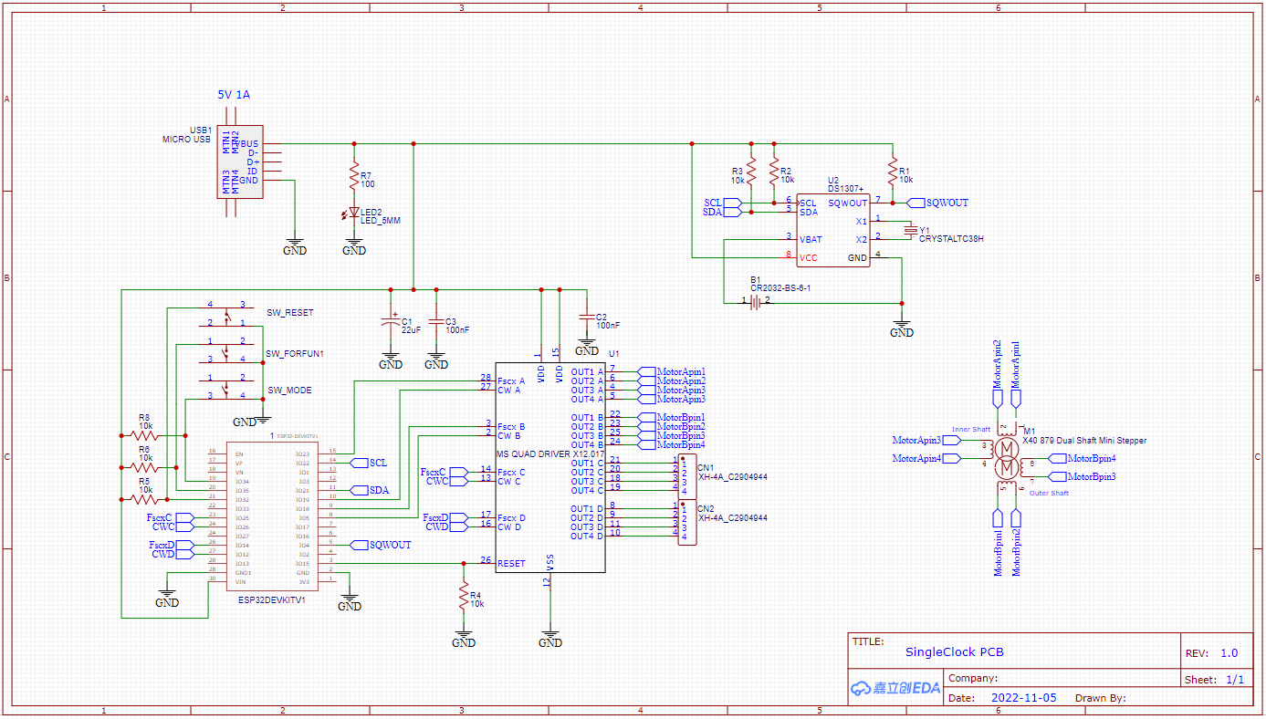
11/24/2022 - PCB done
11/24/2022 at 03:40 • 0 commentsThe PCB is done and I've also changed a few errors in the hardware schematic. There is also room for connecting another motor clock, because why not have the possibility. I have also added two hall effect sensor, just in case I want to make some sort of homing functionality. I have also added pin connections meant for some push buttons.
Exciting stuff! Will hopefully get these babies from PCBWay soon. In the mean time I will 3D design some case for the clock.
-
10-11-2022 - Found a bug
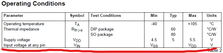
11/10/2022 at 19:07 • 0 commentsSo since the start I had a bug where no matter what I did, the inner shaft would move randomly, continuously. Sometimes and sometimes not. I always thought that it was my shitty breadboards that was the cause for interference. However I figured I might try to set the RESET pin to 5V input instead of the 3.3V that the ESP provides.
EVEN though the datasheet says otherwise. And of course that works..Will need to update Schematic to insert level shifter.
-
11-10-2022 - God I hate Hardware design
11/10/2022 at 00:46 • 0 commentsSo after spending literally a week figuring out how to make the best BMS system for my clock, while banging my head to the wall, I finally ... gave up. I know squat about battery systems. So a wired clock it is, for now. The schematic is done, and will begin on PCB.
-
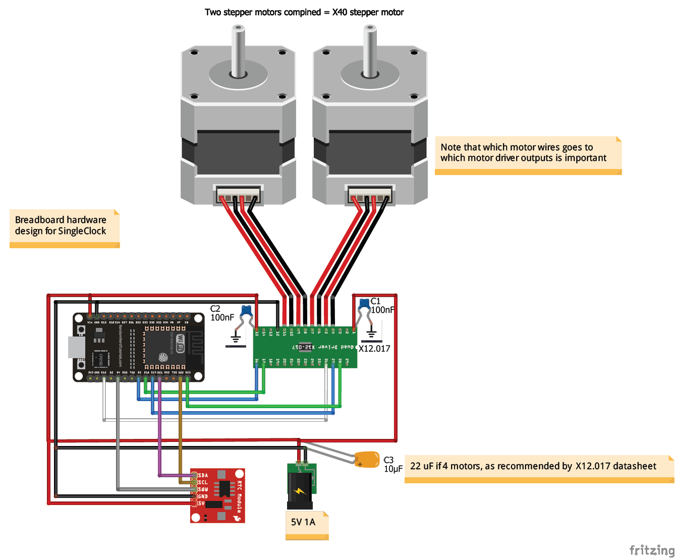
10-31-2022 Breadboard hardware design
10/31/2022 at 02:44 • 0 commentsI made a breadboard hardware design of the components.
The original Fritzing file is on my GitHub to use for editing.
Power consumption of 1A is estimated, will look deeper into that. I might even make it battery driven, for the clean look it could have.Next I will either make the PCB design or 3D design.
-
28-10-2022 Ocean code clean up
10/28/2022 at 07:49 • 0 commentsI have succesfully formatted my 600 lines main.cpp into something a bit more beautiful. Made a few classes and turned my 600 lines into 100 lines. My ESP32 flash was really happy and went from 73% capacity to 50% ish capacity. I have also fixed the bug, where there was missing some steps over long time.
I have pushed my project to github, both the ugly and less ugly code.
The project: https://github.com/flamefir/SingleClock
My last code revision: https://github.com/flamefir/SingleClock/tree/main/src/SingleClock%20-%20clean%20up%20code/SingleClock%20-%20clean%20up%20code
As i am just a student, please tell if any code, makes you vommit.
-
10-24-2022 final software test
10/24/2022 at 19:22 • 0 commentsFinal software test proved good, ish
Timelapse result:
The video shows the analog time on both my phone and on the clock, they follow each other
However the minute pointer is missing some steps, as can be seen in the video.
Next I will fix this step error, then clean up the code!
Making a literal digital clock
This is the start of a bigger project, splitting it up in different pieces. Sit back and relax, its gonna take some time ;-)