Jovan
Jovan-
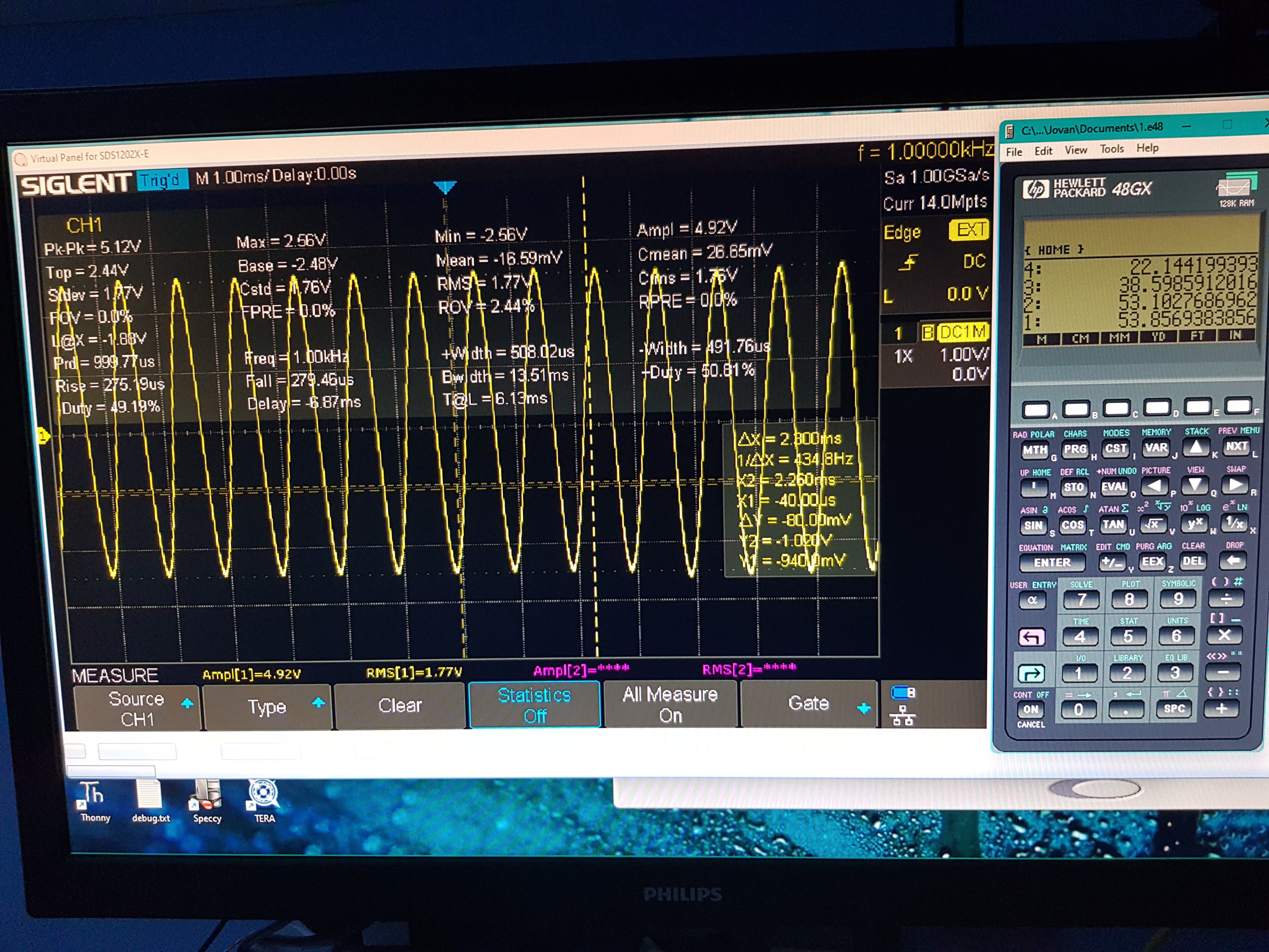
Final testring and confirmation of MOD's THD-N at 1kHz
06/05/2023 at 21:45 • 0 commentsFinal results of my Art DJPre-II MOD. As input I have used my handcrafted ultra low-distortion oscillator with almost immeasurable levels below 0.0004% THD+N, which had to be attenuated by -40dB.
ART-DJPREII-mod2-THD_ for_1kHz(-40dB_Input_WBOscilator-LM4562-0.0004prcTHD).bmp
I hope this modification project will demonstrate that every product can and should be scalable and open to improvements, and that the world would be a much better place with less pollution if every product were made with a little more care and fewer shortcuts, aiming not only for slightly higher profits, but also for greater overall quality.
Best regards,
Dr Jovan Ivković
-
Final modification for max +53dB boost and implementation of LPF
06/04/2023 at 18:52 • 0 commentsI see that I haven't updated the status of my modification work, so let me give you the last update.
On the ART-DJ-PRE-II I modified the following:
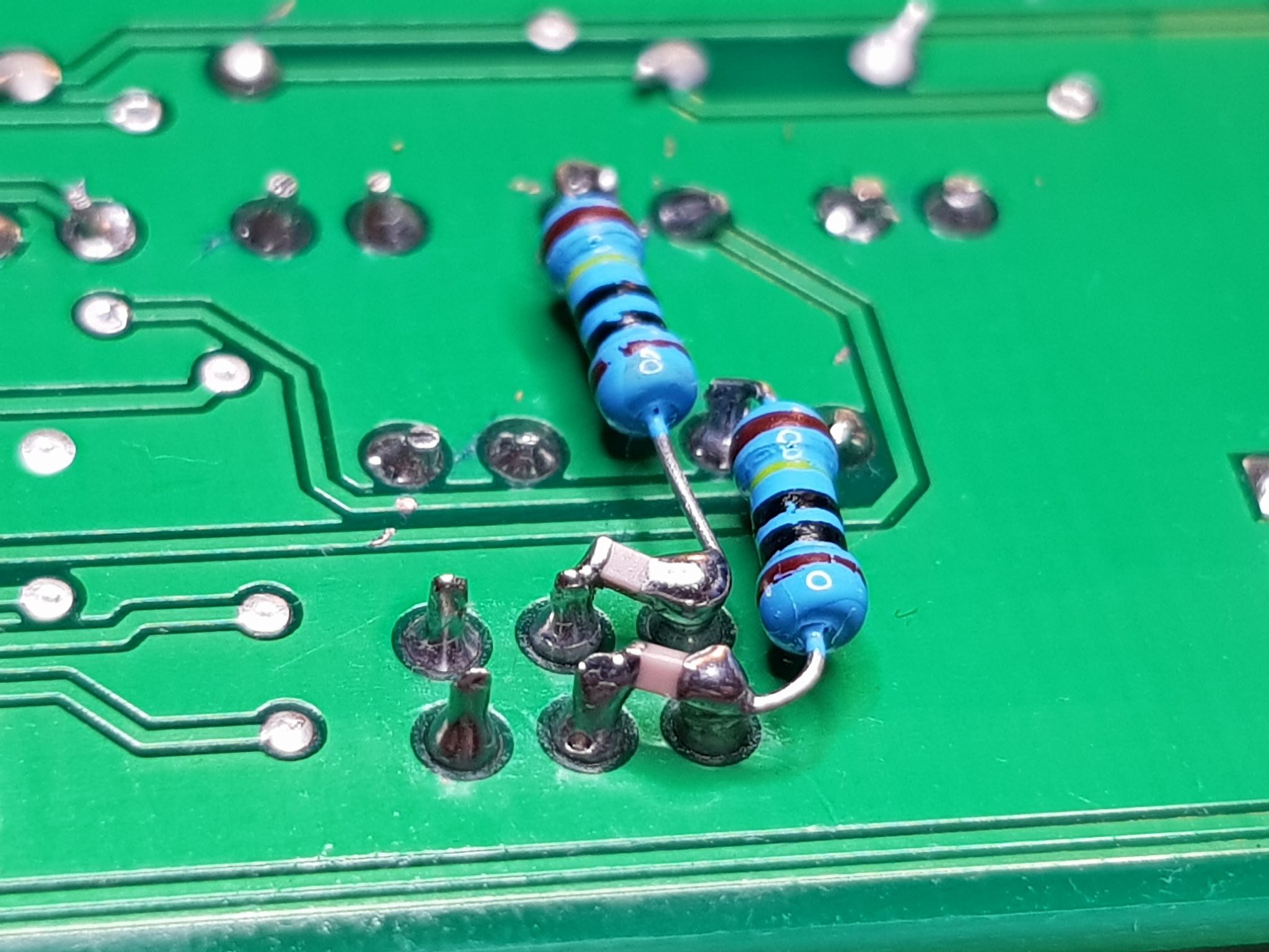
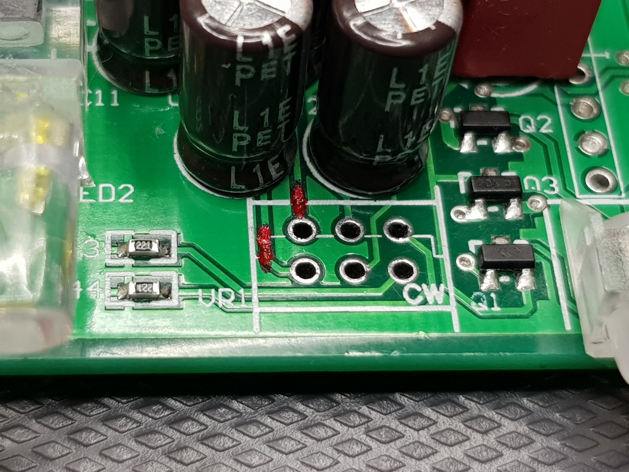
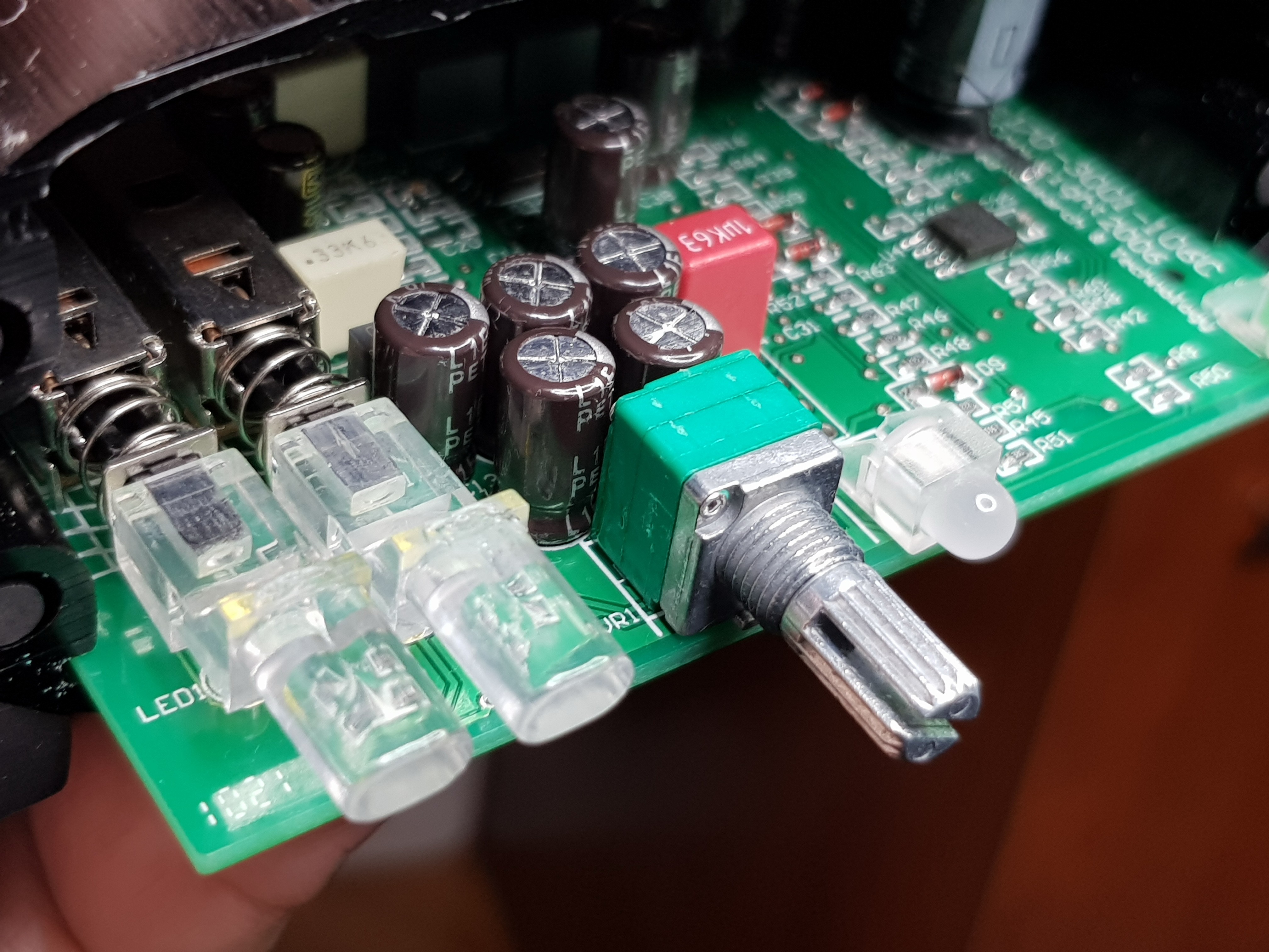
- The old 5k Log Potentiometer was retained but I separated pins 1 and 4 from the existing line and bridged that connection with a 1M resistor with the addition of a 100pF NP0 capacitor between pins 1-2 and 4-5. In this way, I released the potential to get +54dB of gain, and I managed to suppress (LPF) the higher frequencies outside the audible range with the reservation that at least the 2nd harmonic of the sound at 16kHz can appear without loss (illustration below) by doubling LPF cutoff frequency.
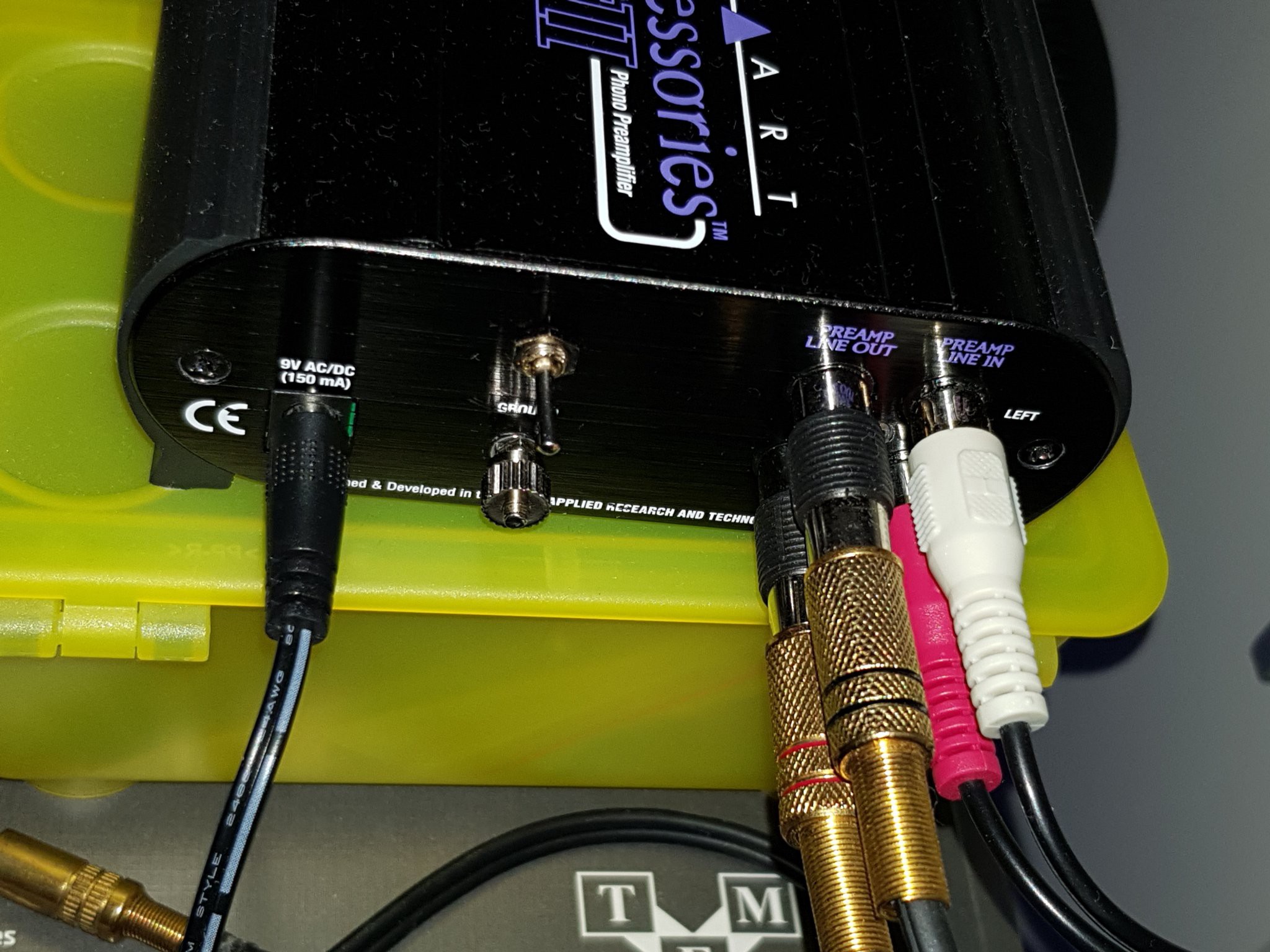
- I then added a 3.5mm stereo banana connector (metal shielded), which is tied to the output using a shielded separate Tasker C121 2x0.25 cable.
I thought about adding the logic for the XLR connector and installing it, but unfortunately, I'm running out of space in the case itself, and I don't need it at the moment, so I don't want to complicate it. I also gave up on the idea of installing an ADC with the addition of a BT controller, which would enable wireless streaming, since as far as I know such a solution already exists in the DJ-Pre-II version.
I am currently working on my own solution for a +60dB Phono Pre. Amp. which in its current design achieves a FOM to RIAA as high as 65105!, which means that the deviation from the RIAA defined curve at any point is less than 0.01dB. Of course, this implies the use of a passive RIAA network, which is at the optimum limit of -22dB with manually matched components. For now, even if it's only in the protoboard phase, the results obtained are fantastic, but more on that in another place and some other time.
Best regards,
dr Jovan I.
p.s. If you need expert help taking your devices to the next level, I'd be happy to help, so feel free to call.
![]()
![]()
![]()
![]()
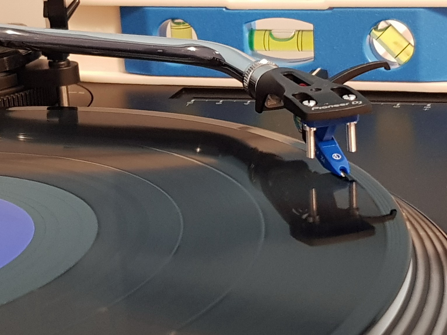
An after final assembling I tested it with my Pioneer PLX-500 Direct drive turntable and additional Pro-Ject Pick it 25A Phono cartridge. And and enjoyed the richness of the sound.
![]()
![]()
![]()
![]()
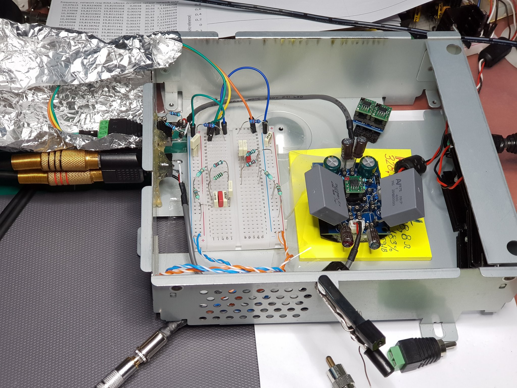
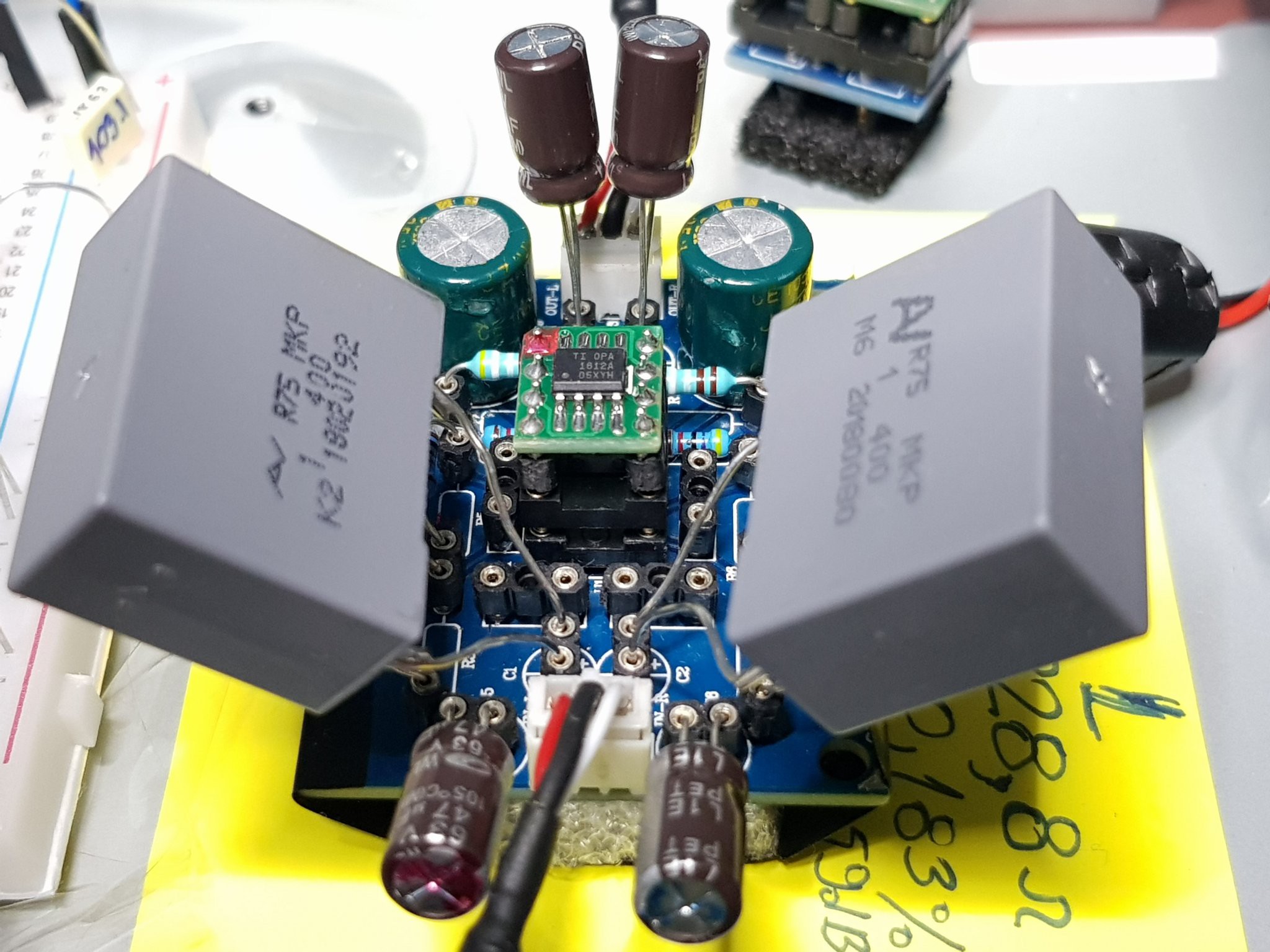
For some future MC cartridges, the current +54dB gain will be insufficient, so I started working on the ultimate audio preamplifier for +60db with minimal noise and based on passive RIAA, ultimate OPA 1612 and the use of PP MKP and FP capacitors.
![]()
![]()
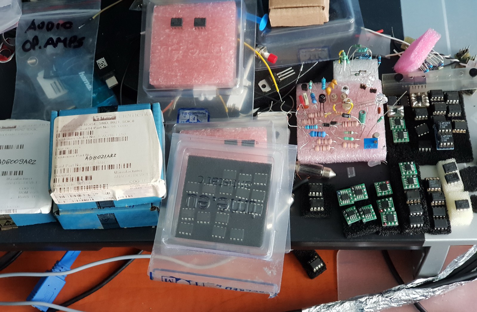
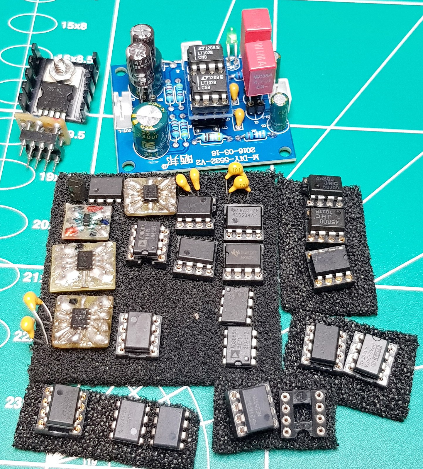
All Op.Amps used in test:
![]()
![]()
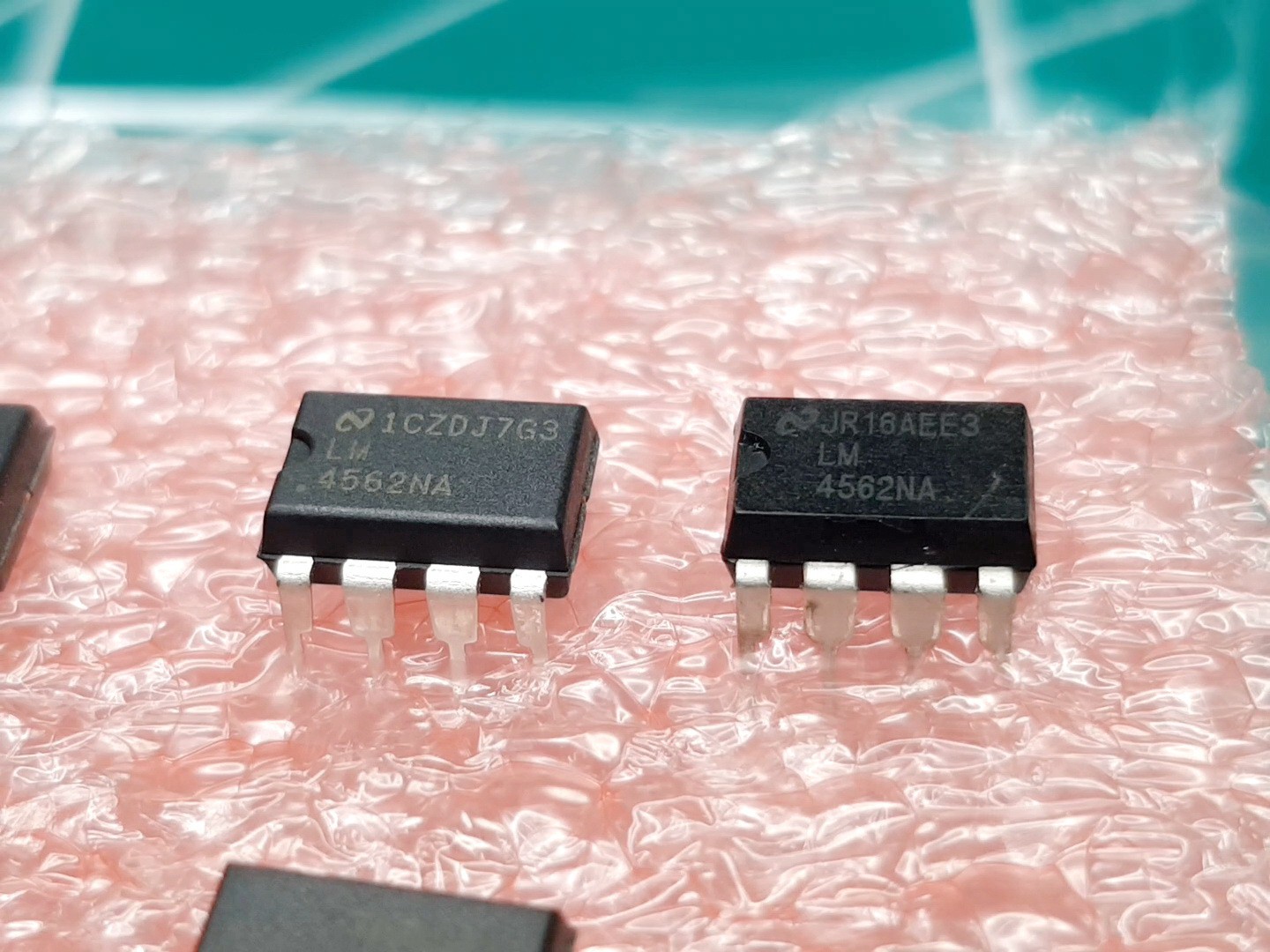
I even discovered along the way that some of the earlier purchases arrived as fakes such as this LM4562 on the right of next figure. Can you spot surface finish?
![]()
Best regards
Dr. Jovan Ivković -
OP. Amps comparation for best on +40dB as low input Omh performer
06/04/2023 at 18:17 • 0 commentsJust one clarification and little quiz. fist an answer to people who (indirectly) ask my why NJM and not some super-duper AD, TI-OPA, LME (like AD80xx/ADA4871 or OPA21/26/16xx, LM4562/LME497xx) Op.Amp for this Pre-Amp modification. Yes I tried loot of them (almost all known) and scientifically measure all of them in real-time application environment, and only after all of that I rejected all prejudices and choose one that have balanced impact factor of 90% on performance and just 10% price. So for example if OPA1612 is just 11% better I will blindly took them even if it is more then 9x more expensive (and it is).
When someone who has done "sponsored" research and says something like the AD79* OPA2132 or LM4562 is 100x better and suggests you replace your component with another one just so you can buy ie. get a 20x more expensive part with "0" impact, just say "goodbye and a pleasant journey".
And now quiz, for all of you who like to get and swap engineered prefabricated IC Op.Apms for "newer, more modern and forum says better Op. Amps" just by "sound of it name" and by looking at datasheets that was prepared by a producers marketing (not the engineering) department to look super-hyper-fantastic.
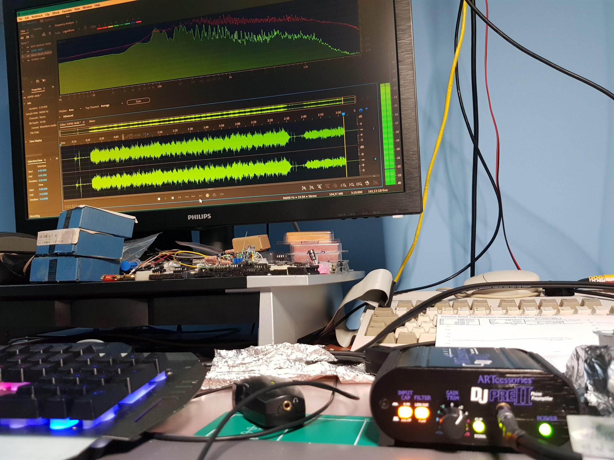
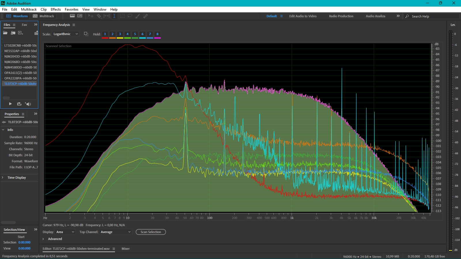
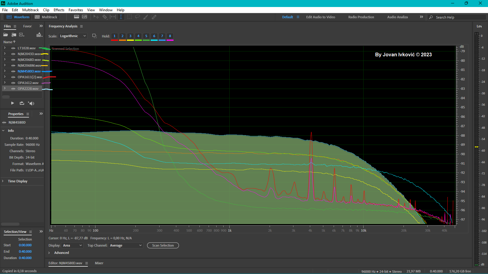
Look on this picture and give me answer what you think, which tested Op-Amp (list of tested is in left-up corner) have which corresponding color line of spectral image? To make it more easy I already mapped TL072CP as last one in "pink".
All Op.Amps are measured with same setup, and environment with BNC-50Ohm terminated canal input, on dedicated 12,6V battery powers supply, while the assembly is placed in a transformer sheet box (better protection against electric and magnetic fields) which was properly grounded. an audio cable ("Taskers C121 2x0.25 Professional Noiseless Audio Cable Low Capacity" was used with profy golden connectors, and setup has:190mO/260pF) routed the resulting amplified signal to an optimized* dedicated sound card. etc.
Take a good look at the picture as some of the answers will surprise you![]()
As a hint, look at this zoomed version:![]()
All Op.Amps was subjected to same conditions in setup done with +40dB gain and inputs was terminated with 50 Omh (BNC) - Recorded with SB (-116dB SNR upgraded) in ASIO mode. -
Can we make it gain more linear and boost some more
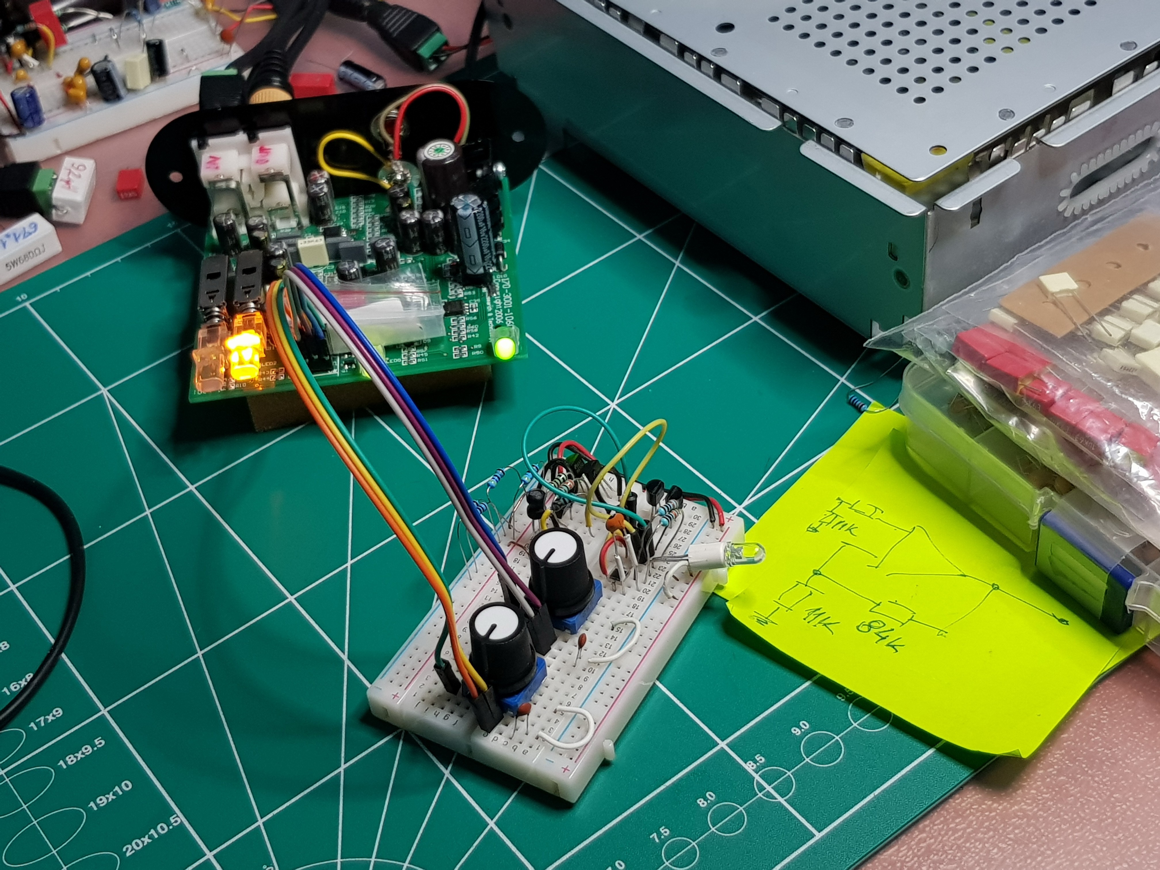
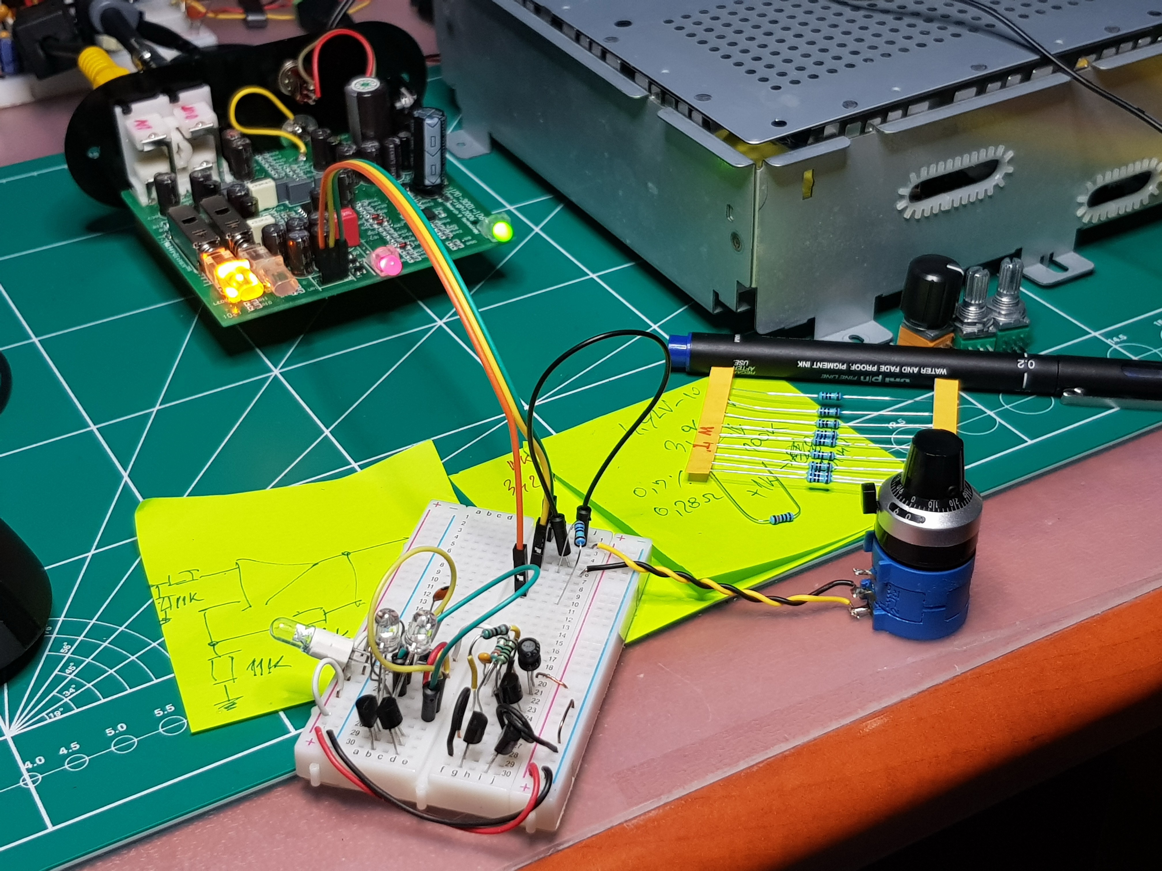
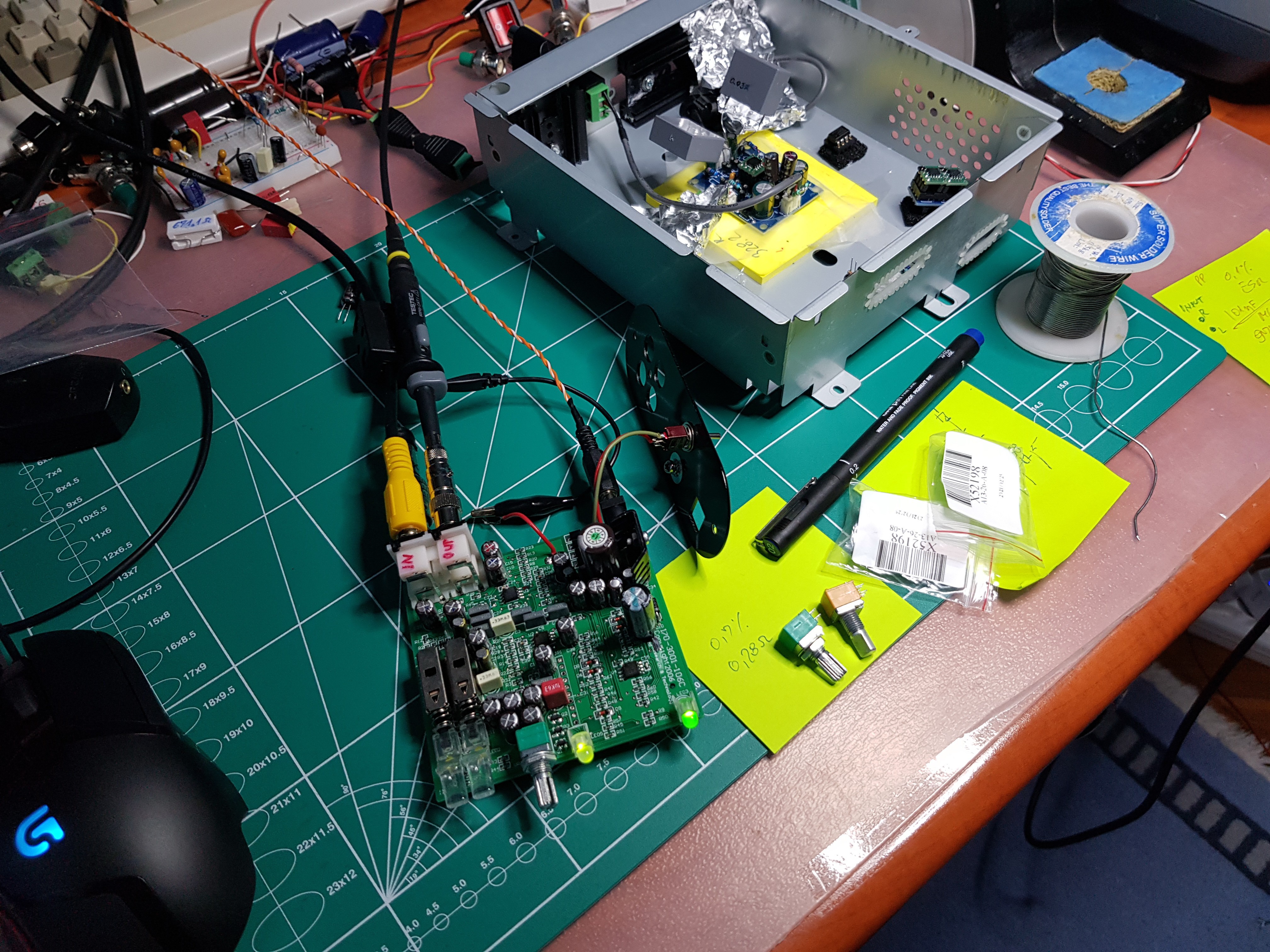
09/21/2022 at 00:54 • 0 commentsThat previous work partially presented in previous post prove to be good mod. That modified ART DJ Pre - II works stable and objectively measured much better then in original configuration. But now I have something even better, observing the position of Gain for my Pioneer Pro-DJ PC-X5 cartridge, which is no other then branded(OEM) AT-3600L i get puzzled why it needs the same ~+4 Gain trim which is like +39-40dB on printed scale, and on the other hand on my made Lab-Preamp (that metal box at my wok bench pics.) measurements shows that it can be put on +34-35dB to get same -1..-3dB signal levels. So I took of little 5k gain pot and find out source of problem is non linear etc. its logarithmic nature of strange applied amplification design.
It look like this:
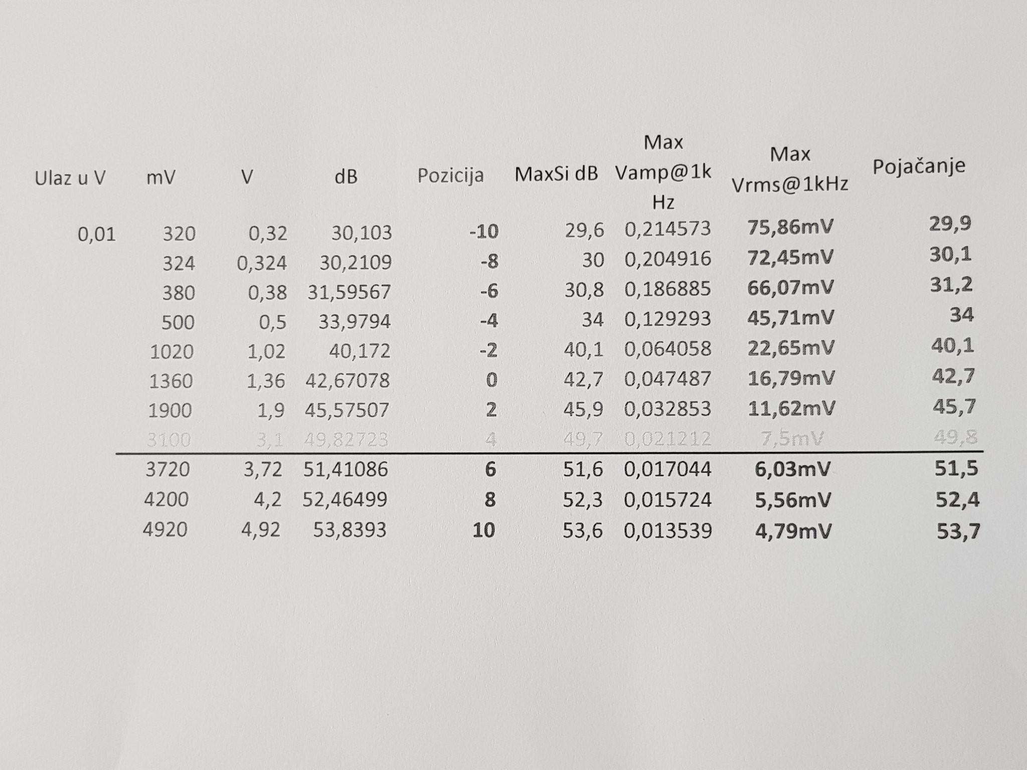
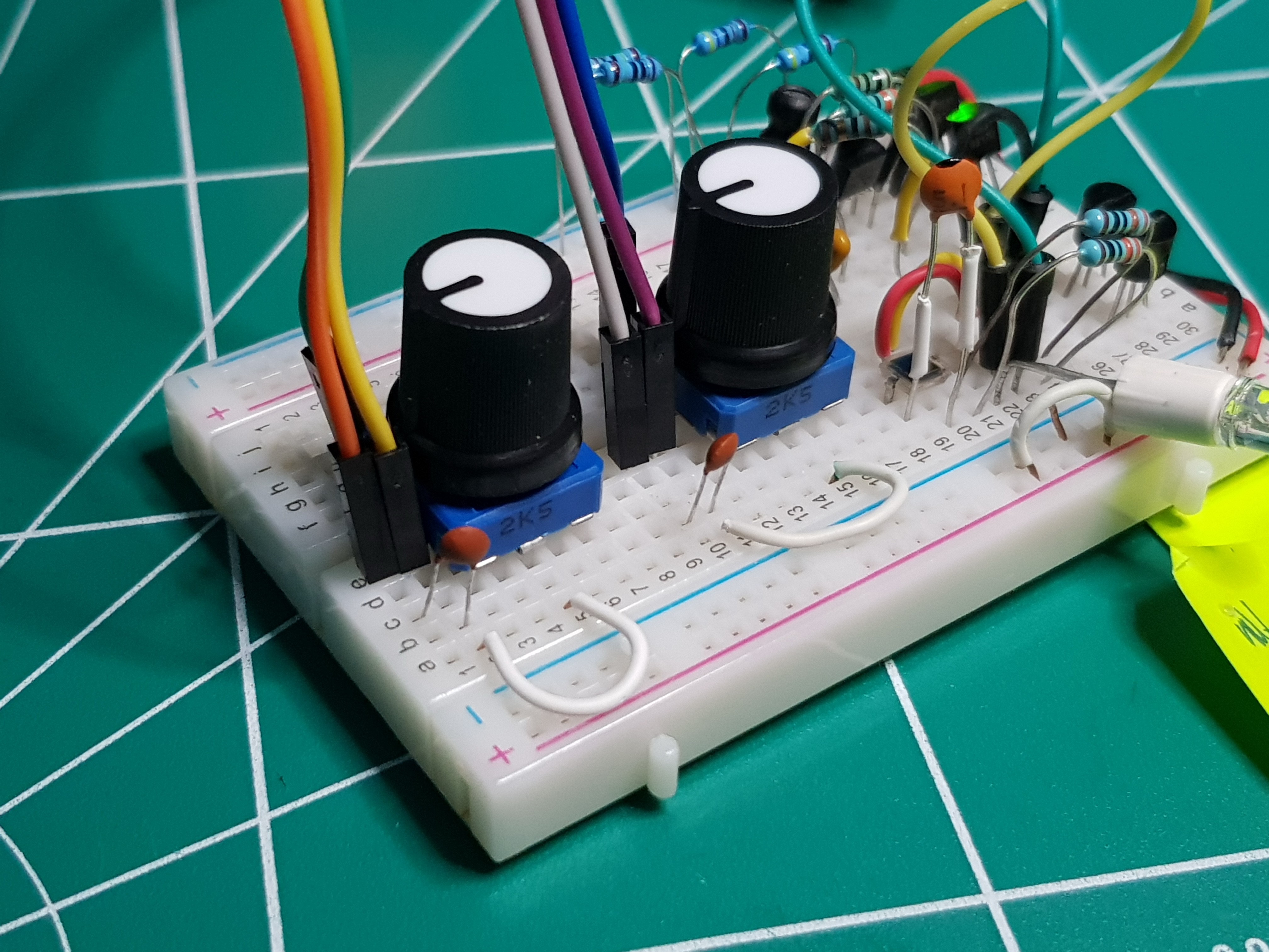
Vin-mV Vin Vout-5k-1M-OFF Ohm Position Vp-p (V) avg(3x) +dB 10mV 0,01 "-10 Begining" 5302 0 0,294 0,294 29,36695 5006 1 0,295 0,295 29,39644 4001 2 0,296 0,296 29,42583 3003 4 0,312 0,312 29,88309 1980 5 0,324 0,324 30,2109 "1/4" 1400 3 0,336 0,336 30,52679 987 6 0,372 0,372 31,41086 Zero "0" at 50% 681 7 0,488 0,488 33,7684 467 8 0,704 0,704 36,95145 "3/4" 25% 84,5 9 1,73 1,73 44,76092 "+10 End" 2,5 10 1,785 1,4849 45,03 In short by "fixing" inverse log position of DJ Pre II by switching to new 2,5k Lin pot. we can get almost linear selection of gain:
2K5 Lin potenciometar Position in % Omh no Vpp "+dB" 10mV 0 2500 0 0,56 34,96376 25 1 0,64 36,1236 33,3 2 0,69 36,77698 50 3 0,88 38,88965 66,7 4 1,09 40,74853 75 5 1,88 45,48316 100 6 4,92 53,8393 To get beyond +45dB up to that +53.8 gain, you need to disconnect Pot pin 1 and 4 or to bypass then with 100k-1M Ohm.
If you omit those resistors for Pot bypass (left open pin 1-2, 4-5) you will get no more then +53,9dB at the best.
So until my 2k Lin Burns (2 gang - stereo) Potentiometer arrives box stays open.Best regards,
dr Jovan I.![]()
![]()
![]()
![]()
![]()
![]()
![]()
-
What sparked my interest for this
09/21/2022 at 00:34 • 2 commentsFirst I have to give one big thanks to people from diyAudio form who for giving me insight into the potential and possibilities for improving an already very solid pre-amplifier design.
Even as audio design is not my primary sphere of interest, the recent transition to LP records and my effort to do the de-claudization and return to analogue "value" starting form the beginning of this year, made me interested in the improvement of the existing gramophone pre-amplifier. the fact that I got a built-in preamp with the Pioneer PLX500 gave me the freedom to upgrade the ART DJ-PRE II that I get as a reserve.
After a thorough analysis of the original set, I noticed that it has a terribly prominent harmonic at 50Hz and its orders. I became interested in the improvement, so I attached it to my linear laboratory power supply and noticed that the harmonic can be suppressed, but also that the device can work with 6.5 - 7V DC, and that it gets heated on one side when connected to an AC power supply.
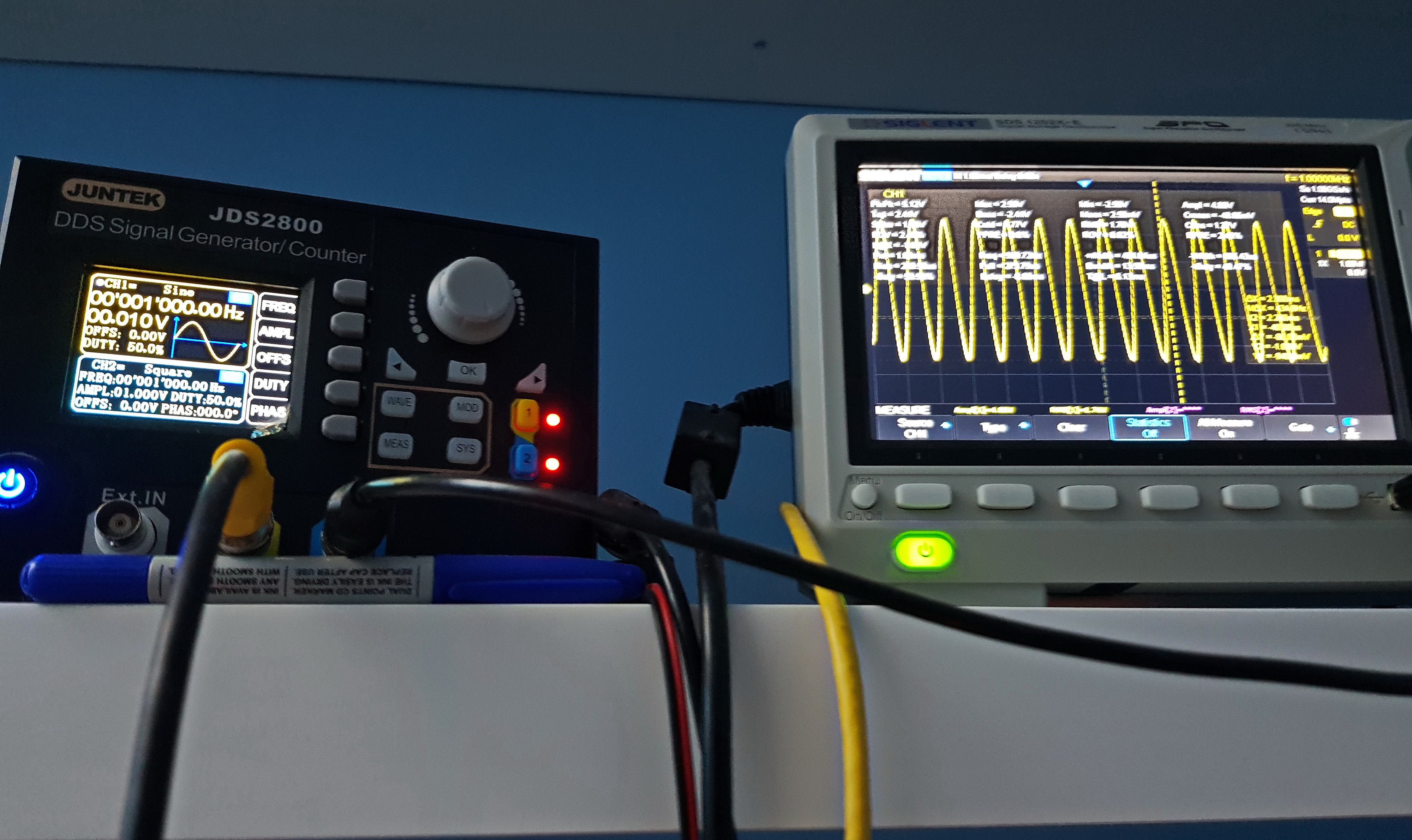
The test with the function generator showed a terrible tendency towards the appearance of harmonics of any dominant frequency (100,500,1kHz ...).
Keeping all the above in mind and knowing the tendency of fellow Audio "gurus" to create things "by ear" because in this engineering field 2+2 can be 6,613 etc. I decided to open the "thing" and see what it was doing. The first thing that caught my eye was the disproportionately poor design of the AC-DC conversion block, the Graetz bridge, then a small 470uF, then the Linear Regulator 7805 at 5V, and after that a small output filter, and only on the Op.Amp is it individually filtered, whatever arrives to them. An ordinary 7805 introduces no less than 50uV of voltage (AC phase) noise, which a good audio Op.Amp with SVR/PSR of -110/120dB easily rejects, but that is not the case here.
Why is it, because someone concluded that a simple CMOS op-amp with low en. of 4nV/Hz (at 100kHz!) is enough to get a solution that will be Low-Noise, "well, little tomorrow, maybe never". The ST TS972 has a typical SVR of -70dB which means it attenuates the noise level in the power supply by about 3162 times, before it appears as a parasitic value at the input of the Op.Amp. We all know that after that it will be 100 to 178 times more amplified. And the result of all that is the hum that can be heard and clearly seen on spectrographs.
The next characteristic of the TS972 is a THD (no noise, distortion only) of 0.003% which means that the first next harmonic will be 3.0E-5 weaker than the carrier signal which is only -90dB, if you think that is a lot add to this value and noise and gain and there you are in the audible range of below -70/80dB. But wait THD value is for AV=-1 only.
Since this Op.Amp needs to amplify the signal from the turntable whose resistance in the case of the MM head is below 1k Ohm, FET and CMOS solutions with low In in the fA/√Hz range are no advantage, moreover the high resistance at their input increases the thermal noise (Johnson-Nyquist noise).
So for a good solution we need any bipolar Op.Amp that can give at least SVR of -110/120dB, and below 8nV/√Hz at 10, 100Hz and even at 1kHz (and not in the ultrasonic range at 100kHz like TS972).
Also, the distortion should be displayed in the gain mode, not like the built-in ST TS972 where Total harmonic distortion is shown at f = 1 kHz, AV = -1!!!, RL = 10 kΩ is 0.003 % This THD is shown in ideal conditions for CMOS (like any other Op.Amp) since there is no Av=-1 gain and the output load is huge, nowhere near practical application for headphones or studio equipment set of 32,45...90 or 600Ohm (or even for 1k and 2.2 k Ohm according to RIAA spec.) This practically means that it is clear why the distorted images are such an expression because 0.003% at 1k becomes 0.03% and when it is amplified 20 times Av=20 ie. 26dB increases to 0.6%, i.e. -44.4dB difference between the carrier tone and its first harmonic.
So I took it upon myself to search the net to see if I was the only one who noticed these anomalies because the searches are full of praise and wonderful reviews full of praise for the -80dB characteristics of this pre-amplifier with also "little" distortion. So the device is even included in reviews and in the analyzes where it is compared with 100-200 USD more expensive models that show similar (in my opinion, frankly poor) characteristics.
All in all, since this post was long enough to make it a little shorter, I tore out all the Op.Amps, Ordinary electrolytic capacitors and thoroughly reworked the power supply with the necessary addition of components.
Since my idea was not to turn a 50 USD device into a 500 USD beast, I gave up on the OPA1612 or OPA2228 which were my primary choice, since the existing state of my inventory with 3-4 pieces I can't possibly replace due to the lack of components on the market and price hikes, I decide to save them for some other/new projects. Next I tested the LM4562 and its successor family LME497xxx and since I couldn't find a reasonably priced SOIC version I abandoned them also, I decided on the suggestion made by NwAvGuy in his analysis. Honestly my favorite for a cheap solution was the NE5532A at first, but it The NJM4580D outperformed it in my tests, and only one small thing decided that I should include the NJM2068D (MD) in the design instead, and that is the equivalent noise level, which in my tests is just behind the leading trio of OPA1612/1602, OPA 2228, and LM4562... even more form 1-10Hz up to about 400Hz its noise level is lower than LM4562 or OP227. LT1028 hash lowest values but i is best that is it hard to teme.
And it has specified and guaranteed RIAA caracteristics NJM2068D Equivalent Input Noise Voltage is as FLAT+JIS A, on RS=300Ω at 0.44 to max 0.56μVp-p
Spec do not show its en(Equivalent Input Noise) value but it si perform better then 3-4nV/√Hz devices on 10, 100 and 1kHz so it have to be below 4nV/√Hz.
Even its mediocre THD-N is shown at near real situation as sum of THD with Noise at AV=20dB gain amplification, VO=5V, RL=2kΩ, f=1kHz and it is THD-N is 0,001%
Simular new design NJM8068 (repackaging) spefied also as 0.001% even show that it can go as low to 0,0007% at AV=100 at 8-9V output.
When Ti put in spec for OPA1612 as stellar level for THD-N like 0.000015%, we must have in mind that it is mesured on no gain platform AV=+1 so that real condition Pre.Amp wil degrade that for any aplification level it performs, so at AV=100 (20dB relative) it is =
20x Log(THD-N/100)+ 20x Log(AV) ---> -136.478+40 => -96.478dB which is translated to NJM specs equal to 100% * 10^(-96.478dB/20) = 0.0015%
Now it is clear why on practical tests "King of the hill" is not always one that we all expect to be.
And the most important thing is when all supplier have stuff an waiting until next year, I managed to buy them for 1 USD each.
My mod list is the following:
Replaced blue LED with green LED which is much dimer
Added On/Off switch on chassis
Added power supply switch (to do this, I interrupted -cut- traces on the bottom of the PCB).
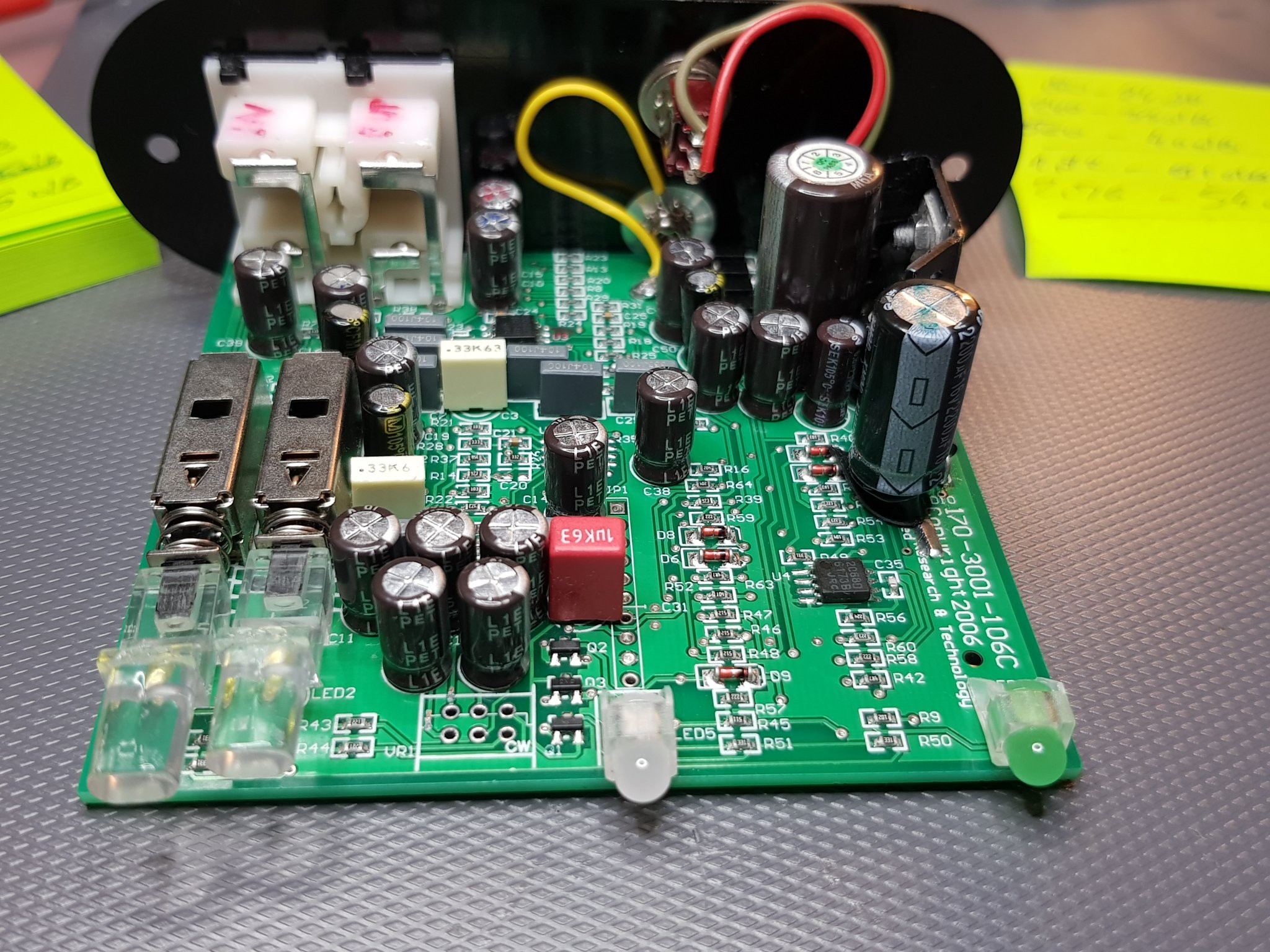
Added 2200uF/25V LowESR high ripple electrolytic Cap. (brand name)
Boost working condition by replacing 5V (Korean) for ST L7810A low noise 10V linear regulator
Added Lin. Reg protection diode for hi cap. load switching
Added another 2200u/25V LowESR high ripple electrolytic Cap. (brand name)
Replace all onboard ordinary electrolytic Cap. and replace them with audio grade (brand name) equivalent LowESR high ripple electrolytic Cap From Panasonic and Samwa.
Replace 1uF electrolytic on WIMA MKP in audio path and with MKT on power path.
Replace condensers for 100pF input filtering
Replace addition 100pF condensers for 200pF filtering with 220pF NP0 ones, so that now I have 0pF and 220pF input filtering
And most importantly I replace TS972 with little larger NJM2068MD (D-sufix version for guaranteed RIAA req.)
This post is becoming even longer so I will put all other stuff to my blog
All of that work will be explain in 4 modification phases (or maybe more) in this Project.
Best regards ,
dr Jovan I.
Audio - Phono preamplifier boost
Clean hack of the otherwise very solid ART DJ-Pre II phono preamp with the aim of improving the existing design and enhancing its features