 Martin Goodwell
-
1How to build your cyberdeck
A Spark
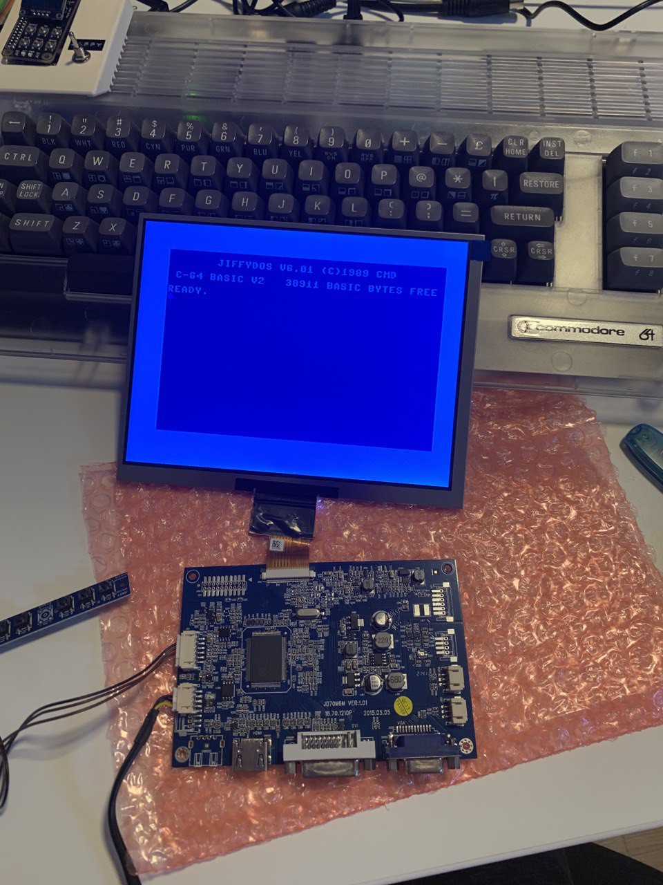
When I saw a 8 inch 4:3 display online, I was hooked. It even featured all the inputs one can dream of: HDMI, DVI, VGA, and composite.
4:3 is important because it's close to the original aspect ratio of CRT monitors.
The idea was born: "I could build a cyberdeck out of this and one of my C64s."
![]()
The display consists of the actual display, a driver pcb, and a keypad to control the monitor (select input source, control brighness, power on/off, etc)
-
2Printing the display enclosure parts
A home for the display
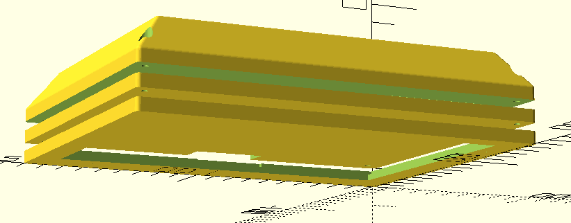
The main part of the project would be to design and create the enclosure for the display. So, here we go
![]()
The enclosure consists of 3 layers:
1st layer (bottom-most) actually holds the TFT screen. (display_tft_front.stl)
2nd layer (middle one) will act as a backplate to the screen, and be the mounting point for the driver pcb. (display_tft_middle_6.stl)
3rd layer (top-most) will act as the protective cover. This will need openings for the various connectors. (display_tft_back.stl)
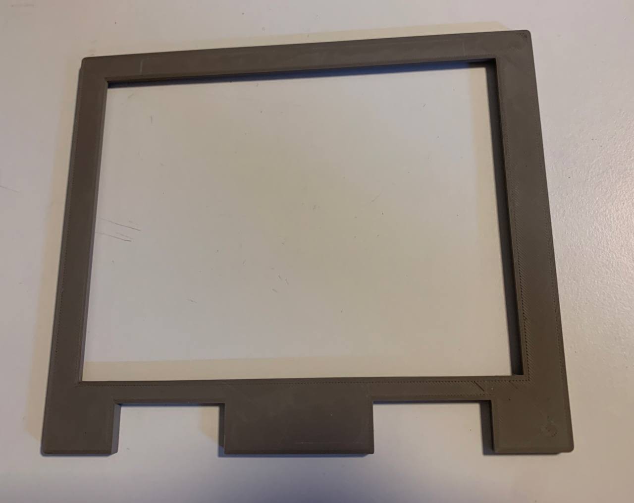
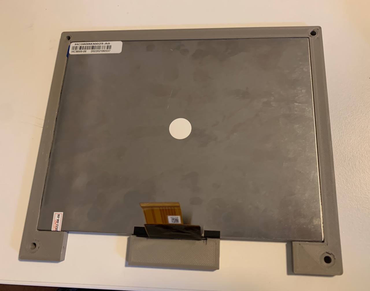
The screen layer
This would keep the display in position.
![]()
As the three layers of the display will need to be fixed together, this layer also contains 4 openings for screw inlets. So, the screws fixing the three layers will come in from the back side and end up in this layer.
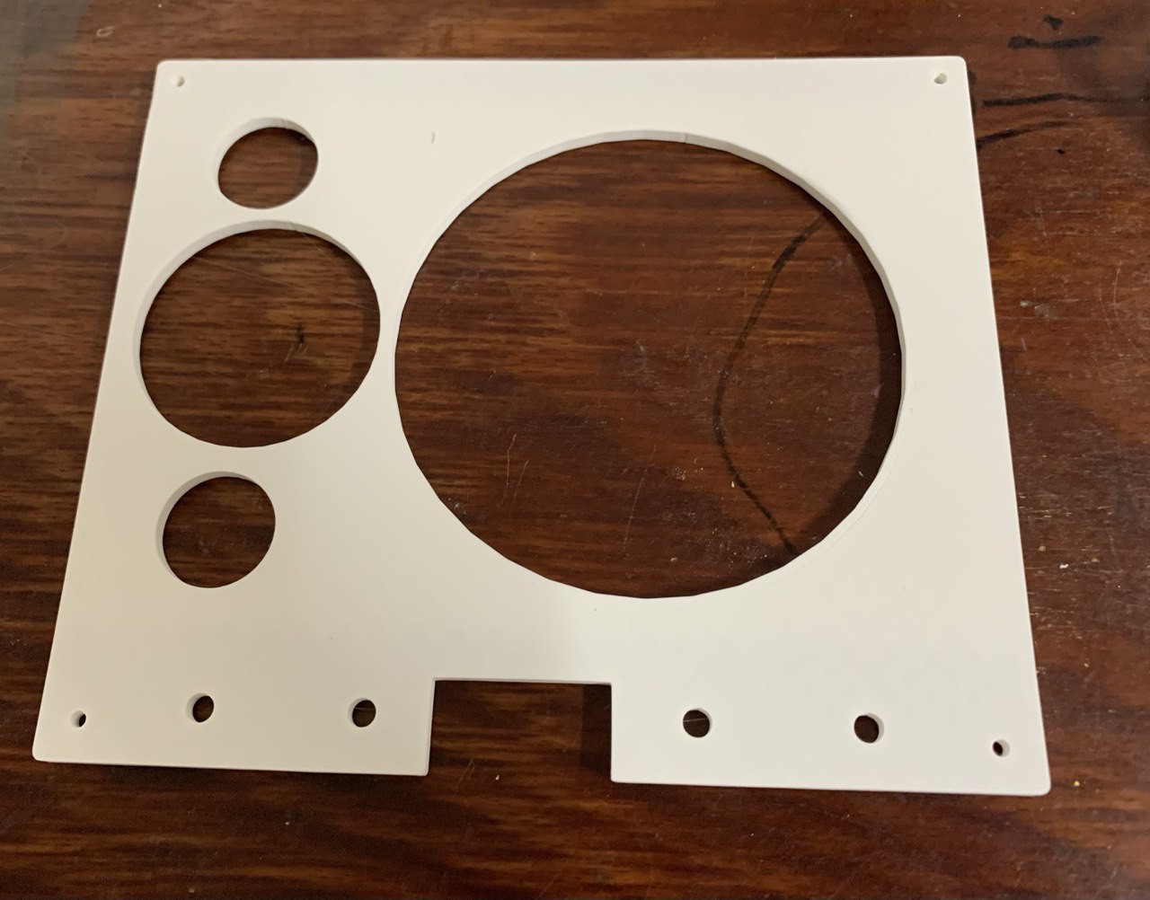
The middle layer
This would keep the screen in place from the back side, and it provides the mounts for the driver pcb.
![]()
The square left-out space at the bottom is needed for the flat-cable connection between driver board and screen.
The four big holes at the bottom will be used for fixing the hinges on the display case.
The four small holes at the corners provide a way for the screws to finally fix the layers together.
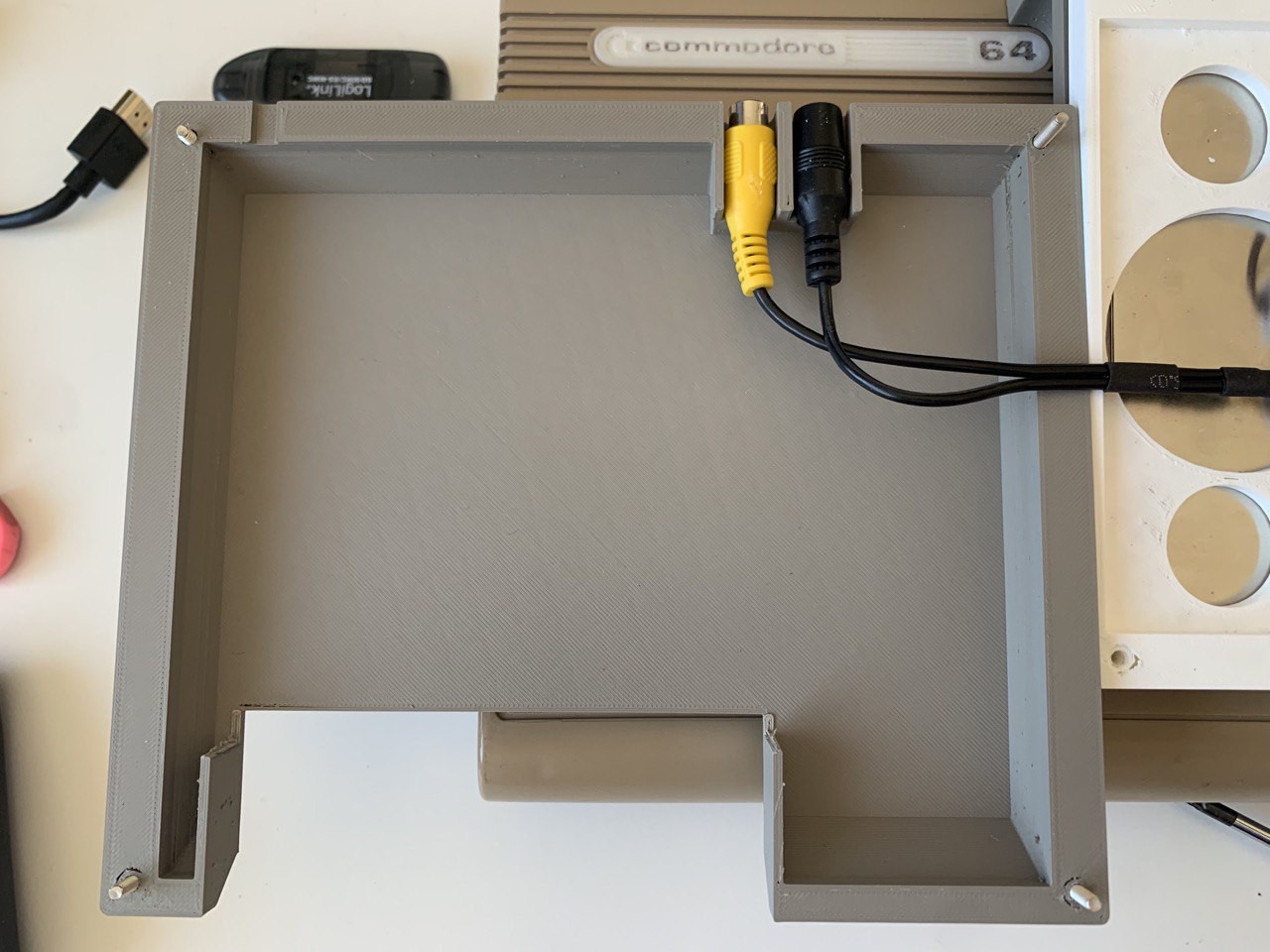
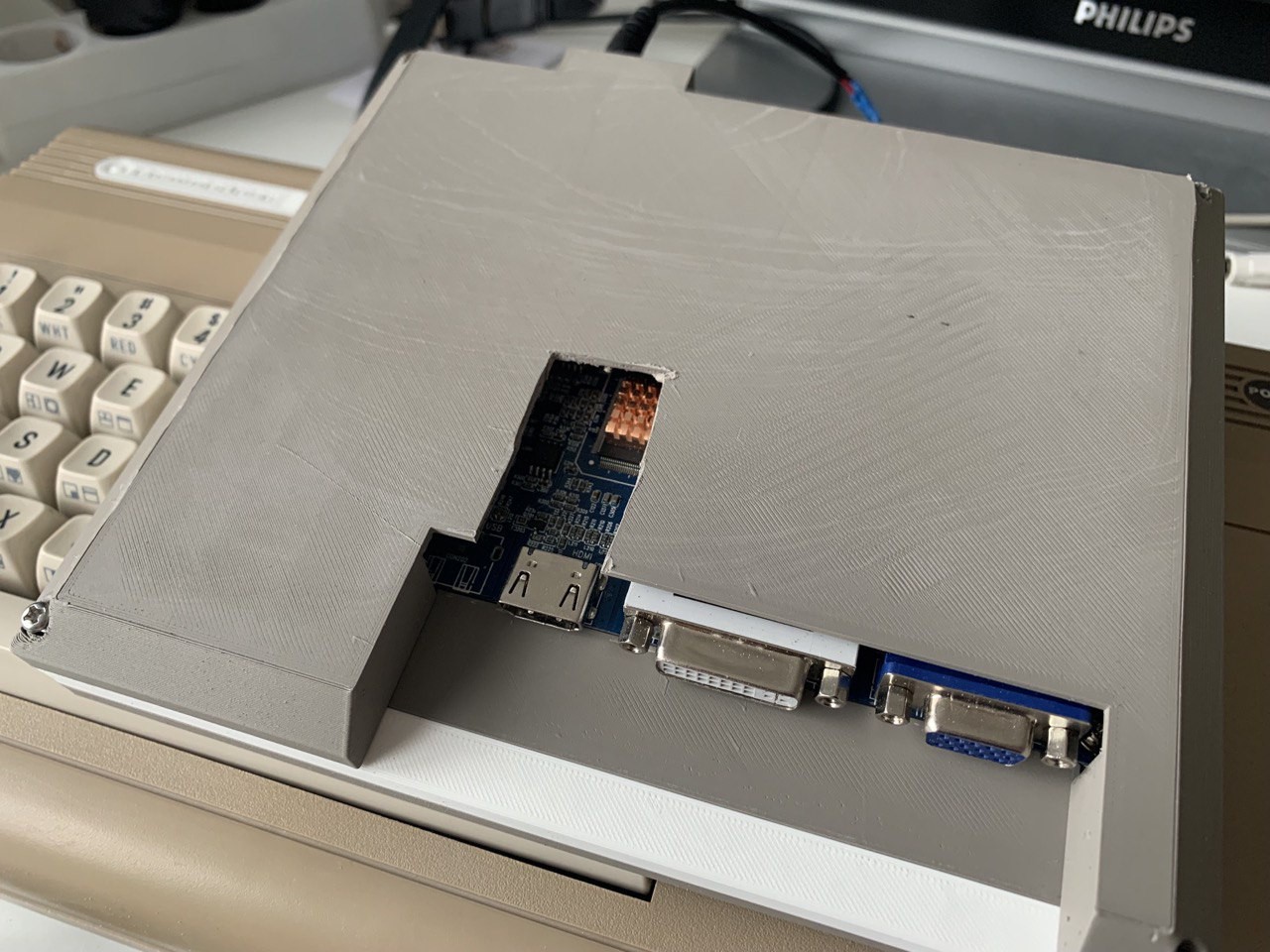
The back cover
This not only acts as the protective cover (it literally has your cyberdeck's back), it also provides openings for the connectors of the display.
After all, the display should not only be usable with the C64, I'd like all the connectors to be accessible from the outside.
![]()
-
3Assemble the display enclosure
Place four M3 screw inlets into the 4 corners of the front-layer
For the middle layer, you'll need four M3 inlets for fixing the driver board, and another four M5 inlets for fixing the hinges.
Melt these into the printed parts and you're ready to connect them (the inlets are still missing from this picture)
Then, place the screen inside the frame
![]()
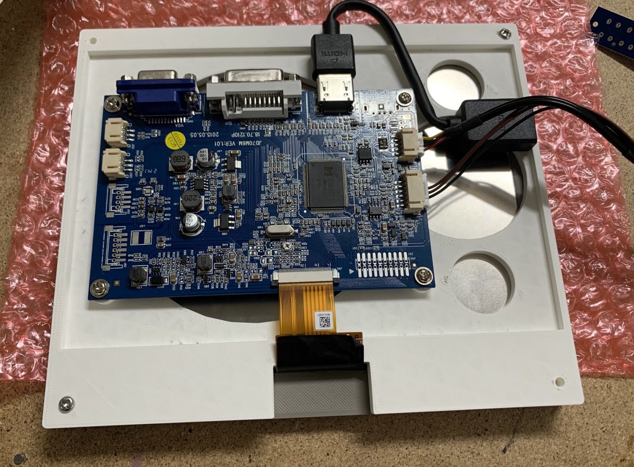
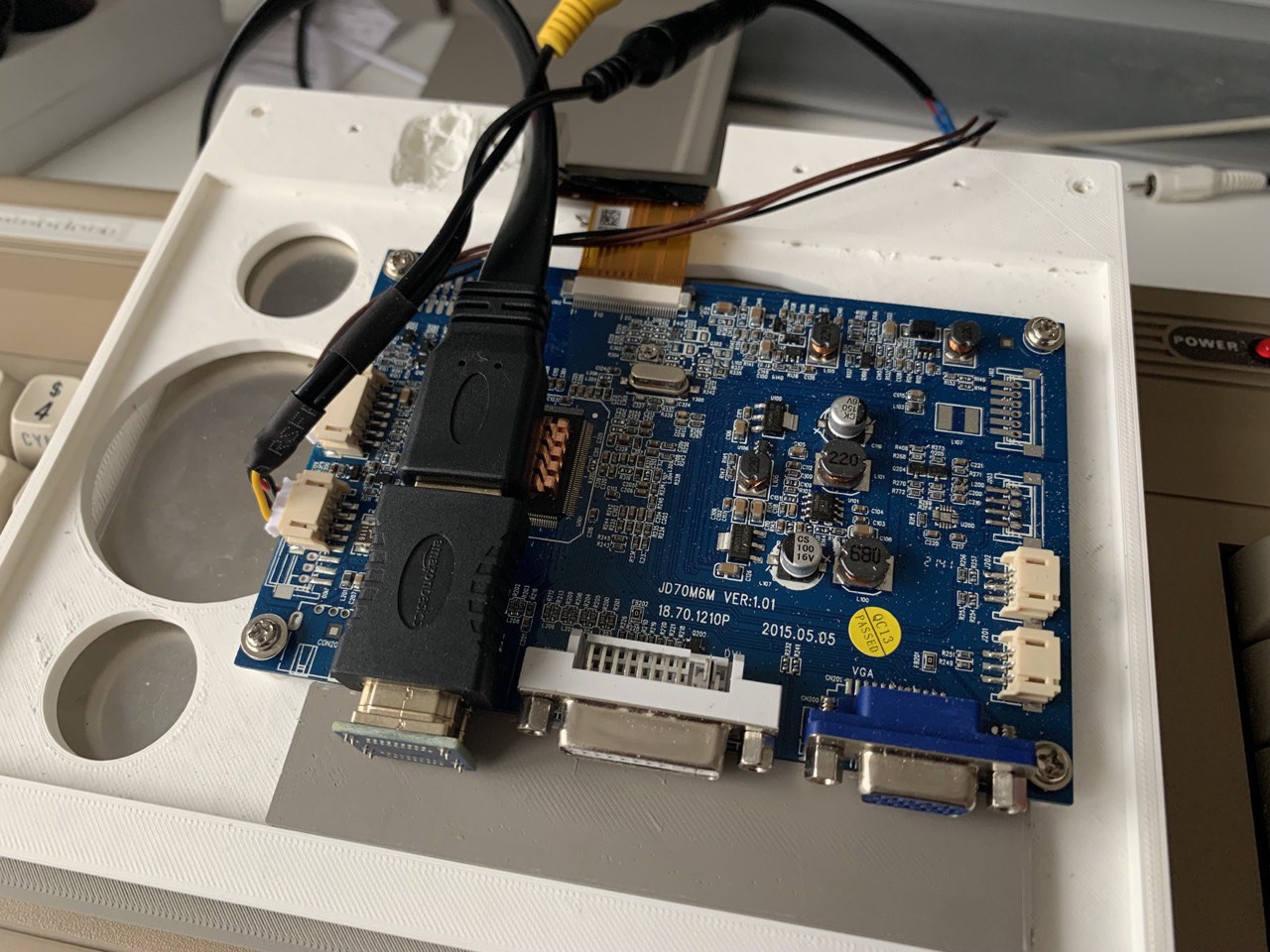
After that, put the middle layer on top of it and fix the driver board to it. Make sure that the flat cable between board and display fits. Otherwise you'll need to either cut or re-draw and re-print the layer.
![]()
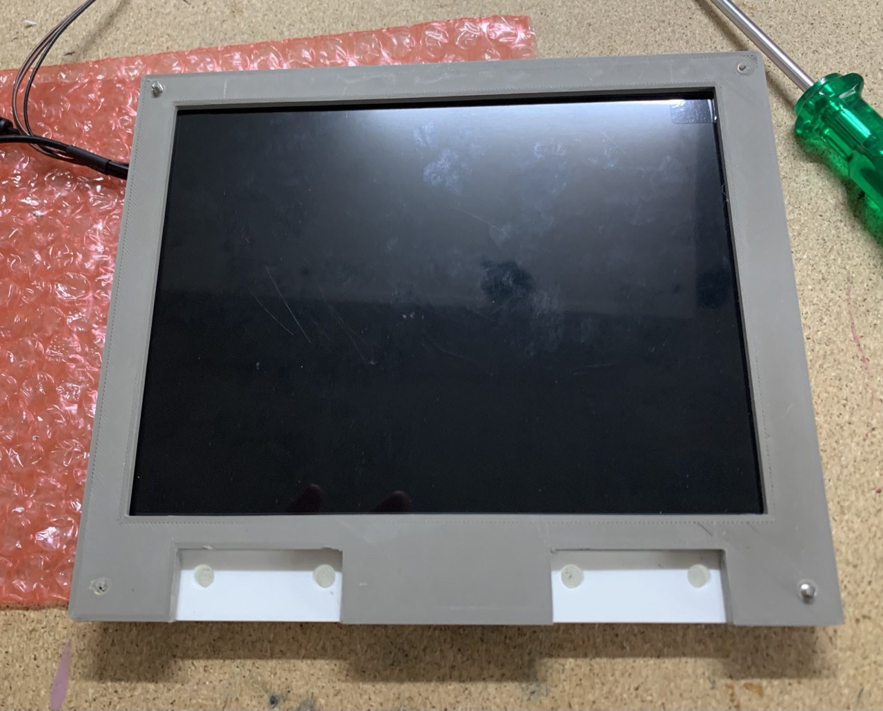
This is how it looks from the front by now. We're also still missing the inlets in the middle layer in this picture.
![]()
Next, you can put the back cover on and fix the screws from the back. You should have a perfect display enclosure by now.
![]()
As you can see, we have a direct few through the round openings directly to the backside of the screen. This isn't nice to see and might be a potential problem for damaging the screen.
So I printed an extra plate that exactly fits the opening. Looks much better. (display_blind.stl)
![]()
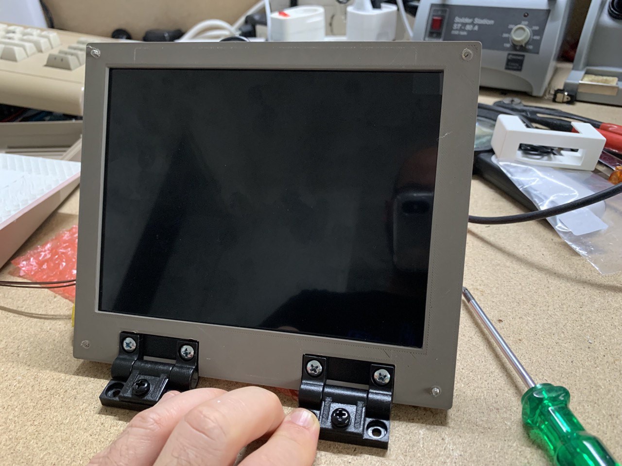
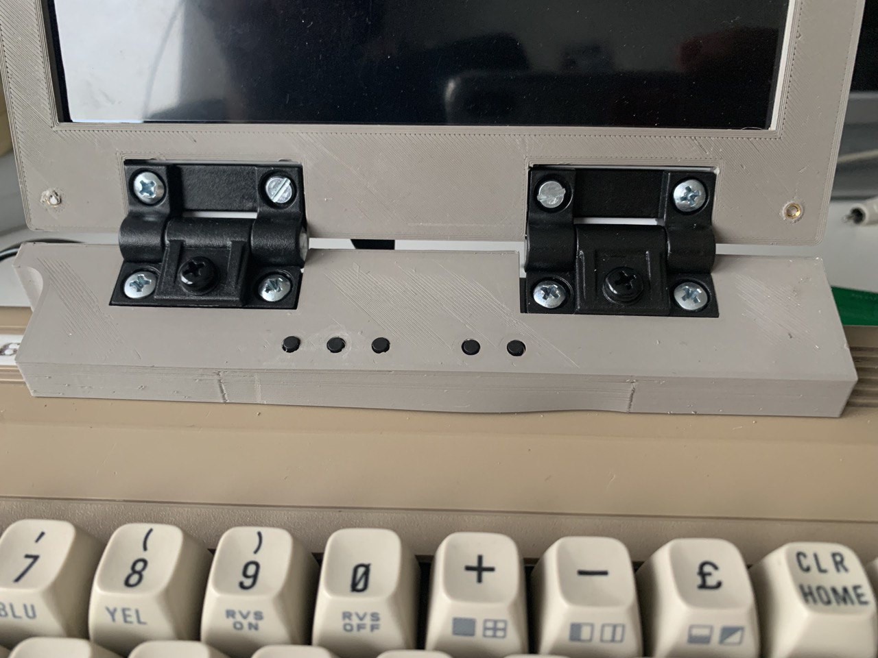
Mount the hinges
With the enclosure being done, feel free to apply the hinges to it.
![]()
-
4Mount the display to the case
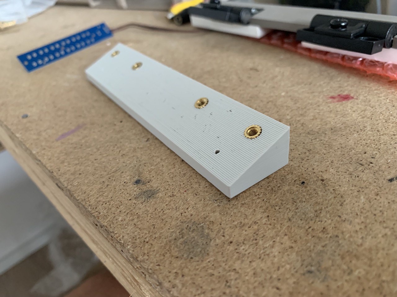
Print the mount
This mount will be used to fix the display on top of the case. This is needed, otherwise the display would collide with the keyboard. (socket_2.stl)
The screw inlets seen on top will be used to fix the hinges we just mounted to the display enclosure.
![]()
![]()
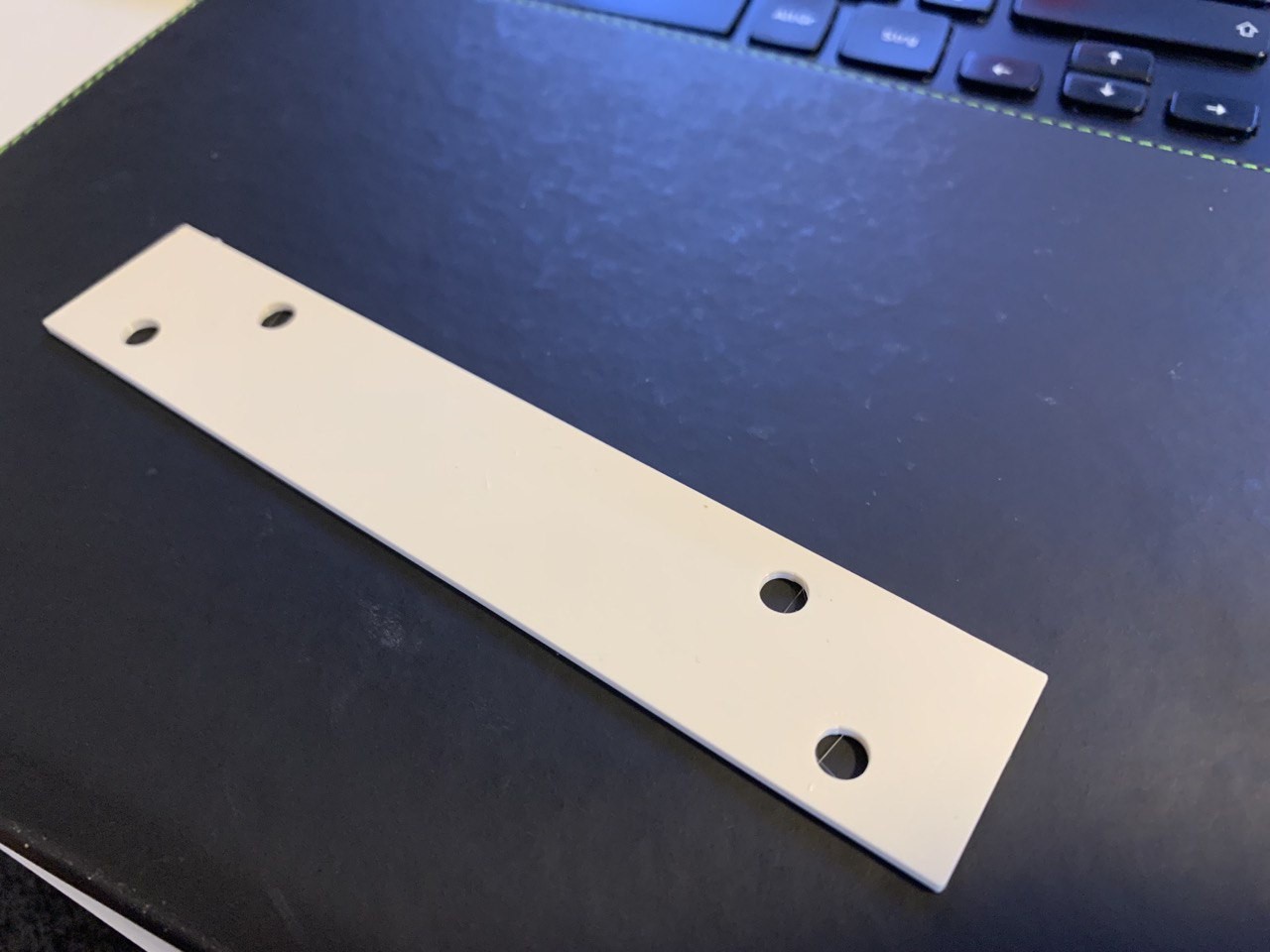
On the inside, there will be a small plate with the holes for the screws in the same position. (socket_plate.stl)
![]()
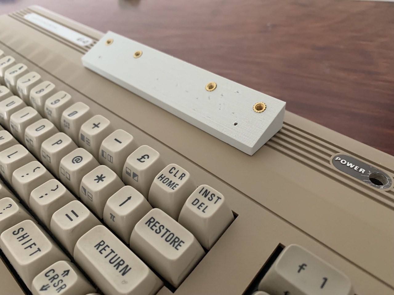
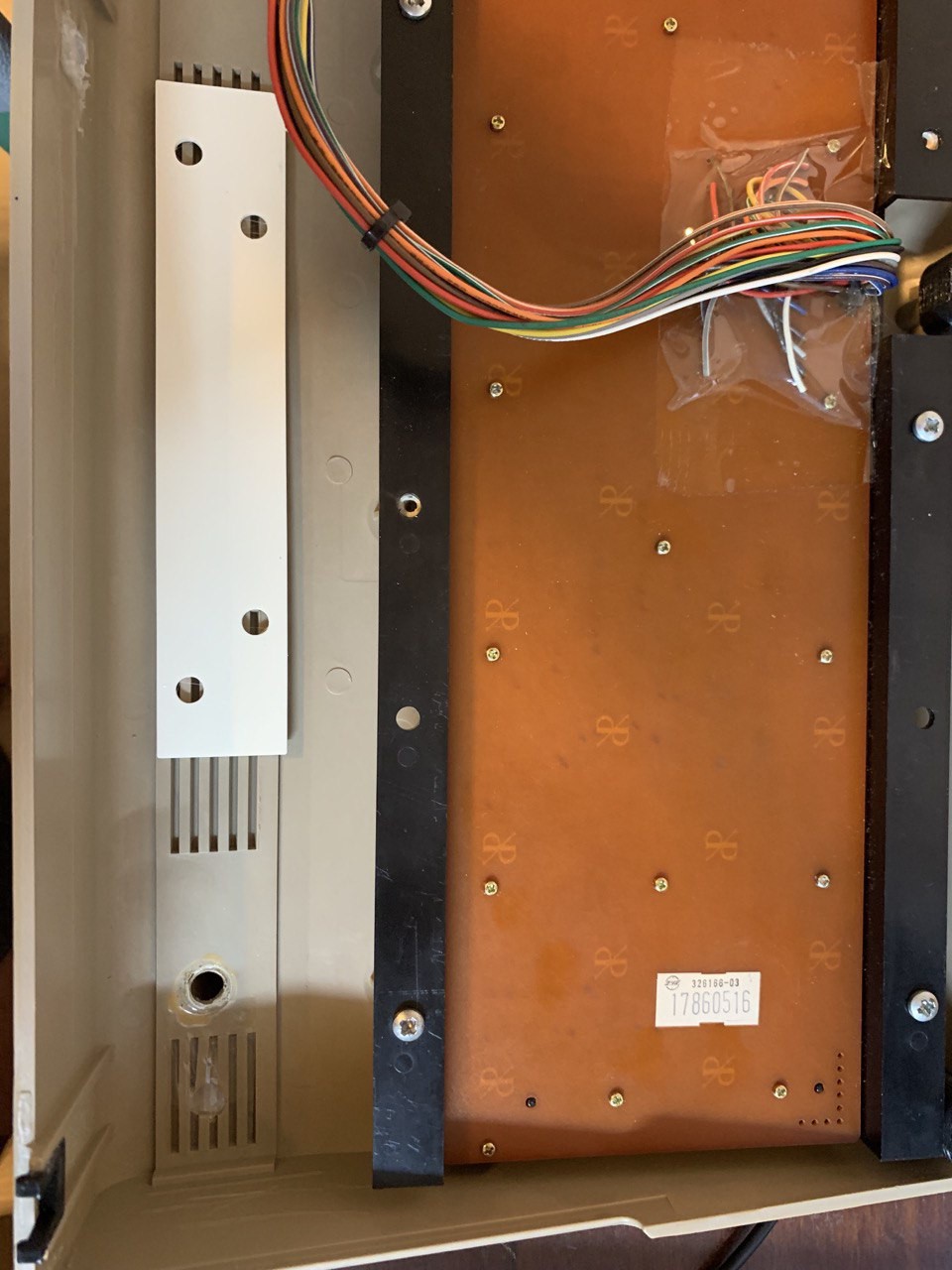
This is how it looks inside. Unfortunately, you'll have to drill 4 holes into the case for this to work.
![]()
As you can see, the case I used has already seen better days, so I didn't use a perfect case for this, but one that was already "modified".
Mount the display
The hinges can now be fixed to the socket on the case.
![]()
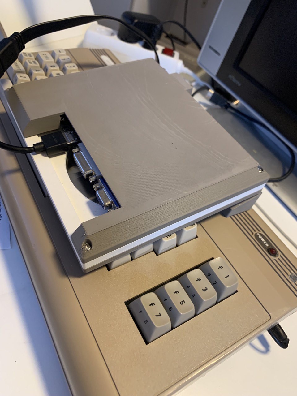
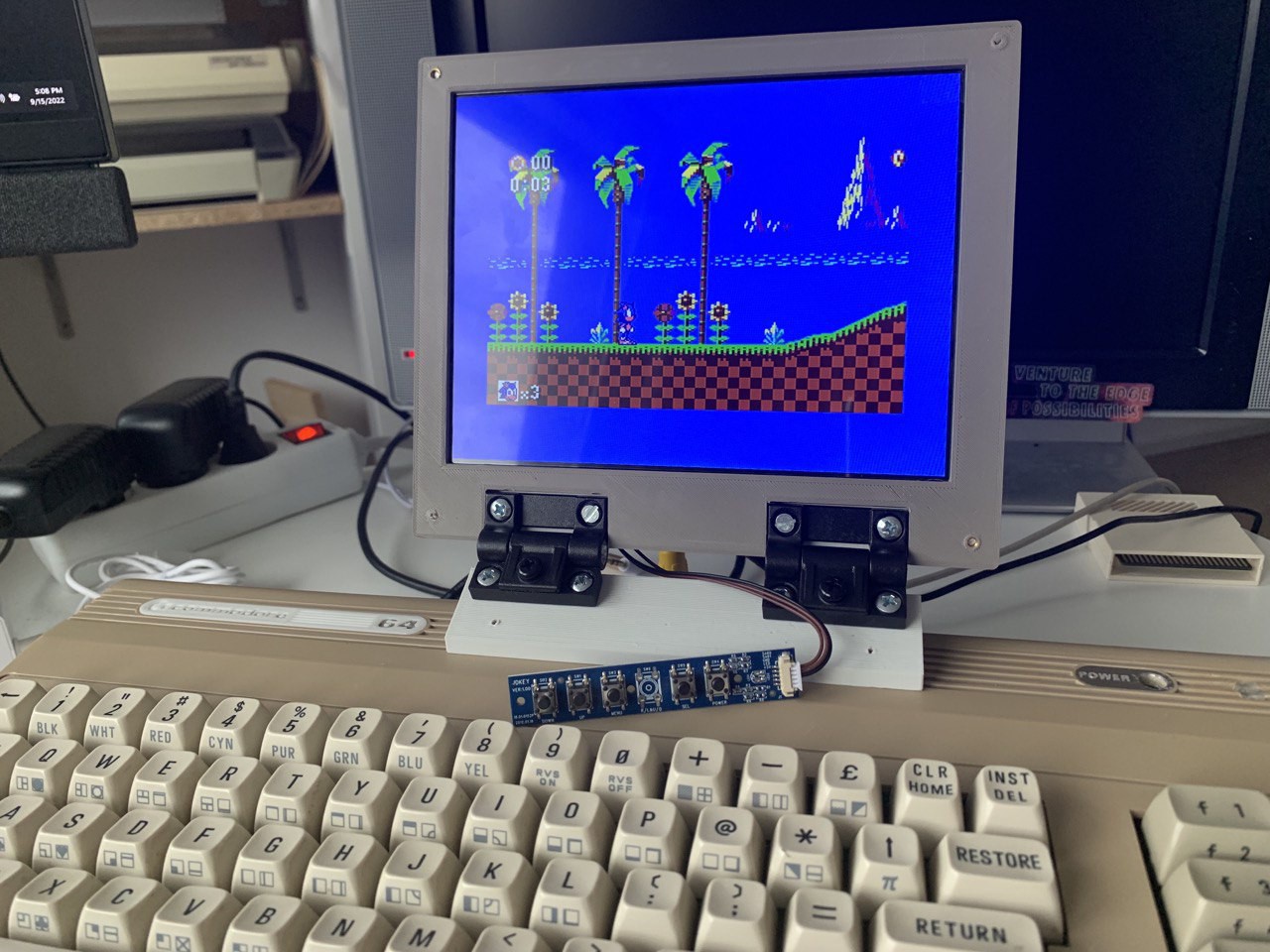
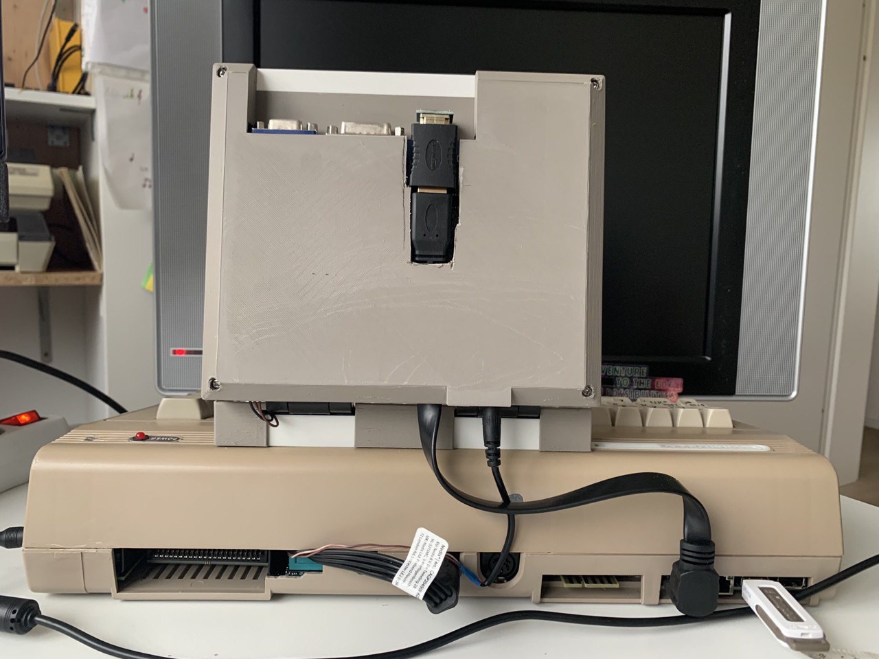
Testrun
This is also the perfect time to do a testrun. Connect the cables and enjoy a game of Sonic before we move to the next step.
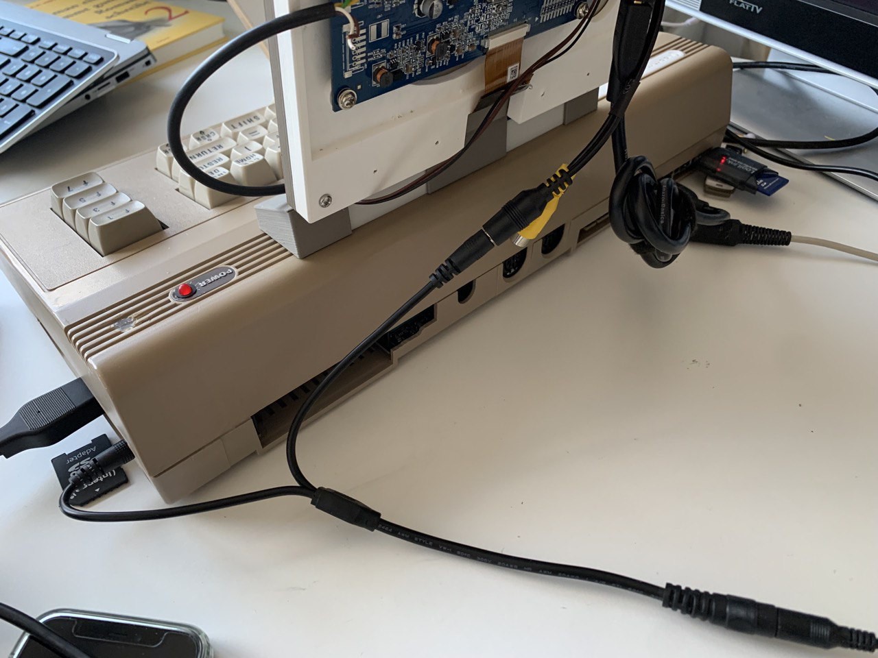
It's the nature of testruns that they look ok from the front, but are a mess in the back :-)
![]()
Cover the socket
The white socket doesn't really fit the brown case and the brown display enclosure. So, let's print the cover for that. (cover3.stl)
As you can see, this is hollow, so you should be able to just slip this onto the socket.
![]()
The cover will also hold the control-keypad for the display in place. This is not the most sophisticated piece I ever designed and printed, but it does the job.
However, this one part might see another iteration sooner or later :-)
-
5The side panel
As was clearly visible in the testrun, we still have cables hanging out.
Mostly this refers to power cables and video cables.
Solving the power cable mess
The C64 has a side-panel that has openings for the power connector, the power switch, and the joystick ports. This is great, but the power plug goes directly into the mainboard. So, there's no way to connect the power plug in it's original place without soldering on the board. And we're not soldering on original hardware here.
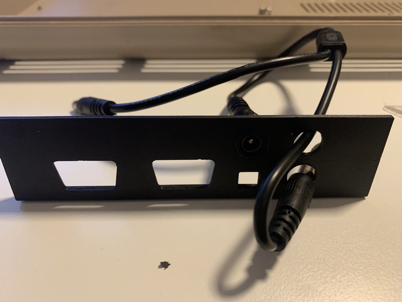
The solution: create a custom side-panel (side-plate_u64.stl)
![]()
Basically, an additional power plug opening is added above the power switch opening (hardly visible in this picture). And we're adding another opening to have a power cable coming out of the case and going into the original power plug.
This is what it looks like: power coming in on top, one side of the y-cable going out again and into the original plug of the mainboard.
![]()
Larger view
![]()
The other part of the y-cable goes out of the case on the back (through the opening of the RF-connector, for example, or next to the module expansion port) and into the power plug of the display.
It is way too long at this point in time, we'll fix that later.
![]()
Video cable
The HDMI cable (this is the Ultimate 64 board, which provides HDMI out) needs to go into the display.
But a regular cable is waaay too long, and a short cable I ordered is just a tad too short. The problem is that the connector on the display-driver board point into the wrong direction.
![]()
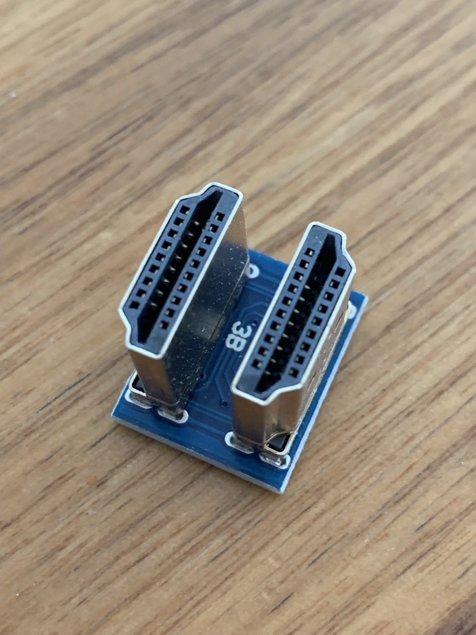
The solution exists: a 180 degree adapter plug
![]()
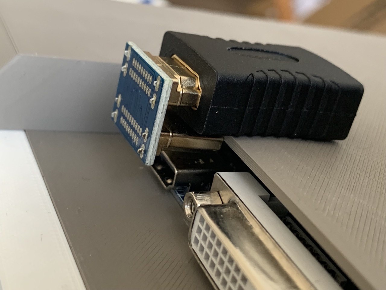
However, this has a male connector, our cable is also male, so we need another adapter
![]()
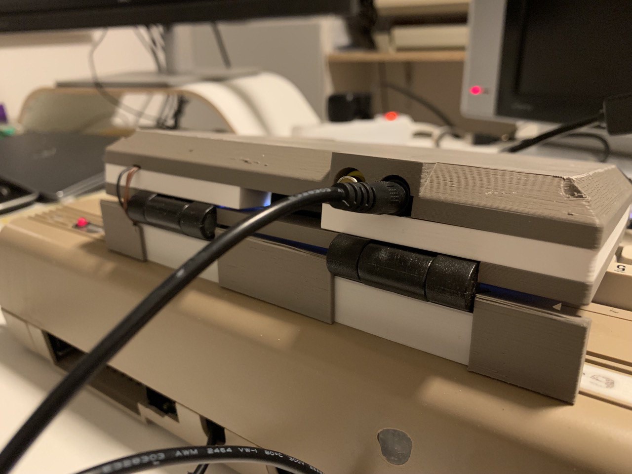
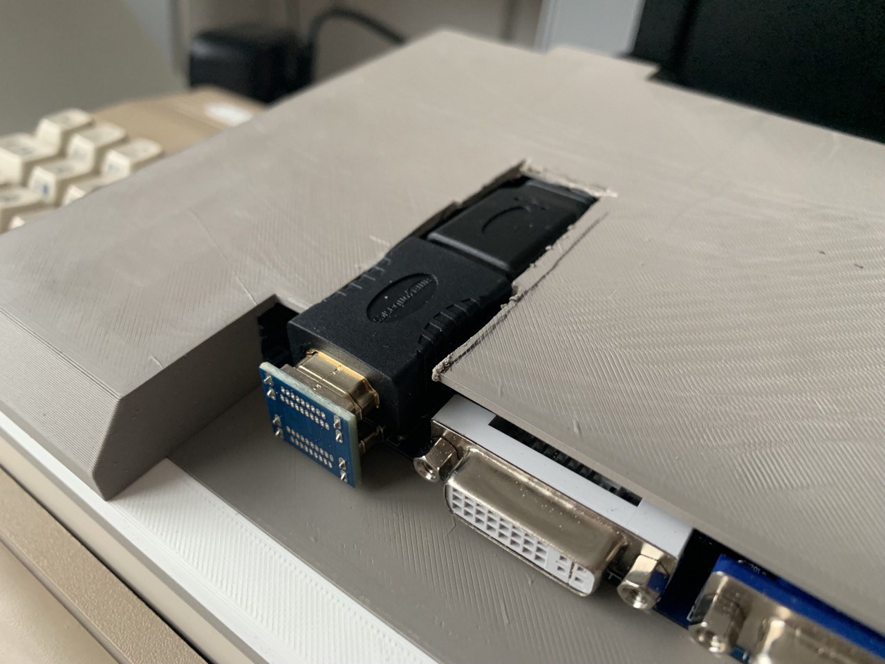
Next challenge: with the adapter in place, the female/female connector collides with the enclosure. As I didn't want to spend another couple hours to wait for the print to finish, I decided to use a rotary tool to fix the issue.
![]()
And you should, too. Not only do we reduce waste, it's very unlikely anyways that my print models exactly fit your project. So, just think whether you need to re-design the 3d model, or if you can just make the existing one fit by using rotaty tools and glue.
![]()
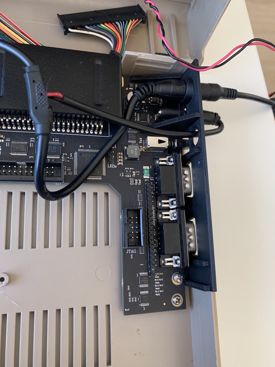
While doing this, the idea was born to keep the cable inside the enclosure as much as possible, as opposed to running it on the outside.
![]()
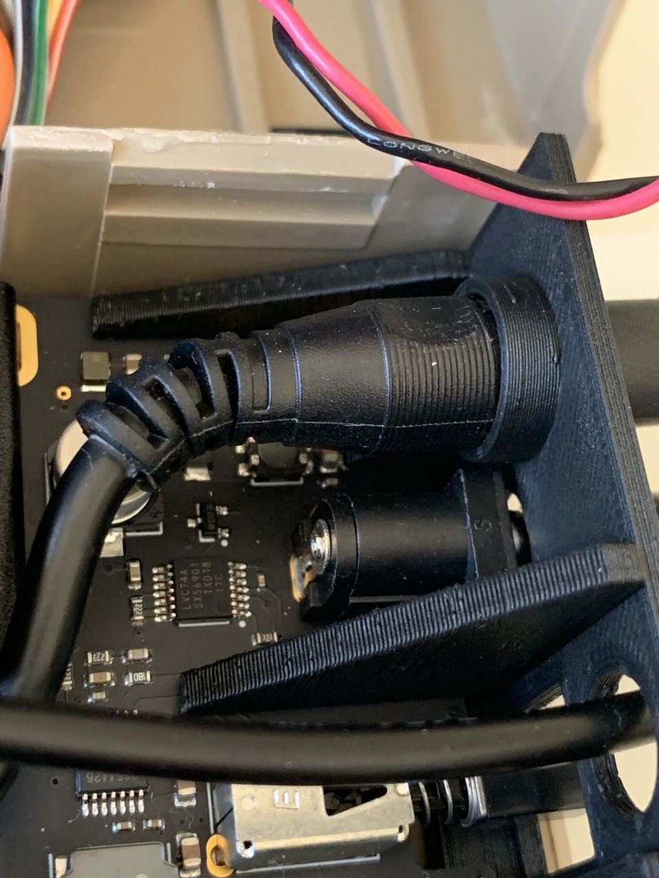
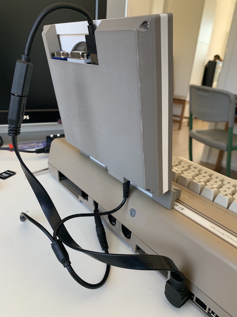
Done. But how did I get the cable into the enclosure, without another rotary tool session?
![]()
Turned out that the opening for the flatband cable is also a perfect fit for this. Pure coincidence, but I can just slip the cable into the enclosure through this opening :-)
Speaking of rotary tools and other "aftermarket" changes to your 3D-prints: on the left-hand side of the picture you can also see the cable for the display control-panel coming out of a small cut in the socket cover, right (left) next to the hinge.
Done
![]()
Looks good already, I'll still need to glue a cover on top of the HDMI-adapter-adapter-cable opening to make it look better. But the cable mess is largely gone.
-
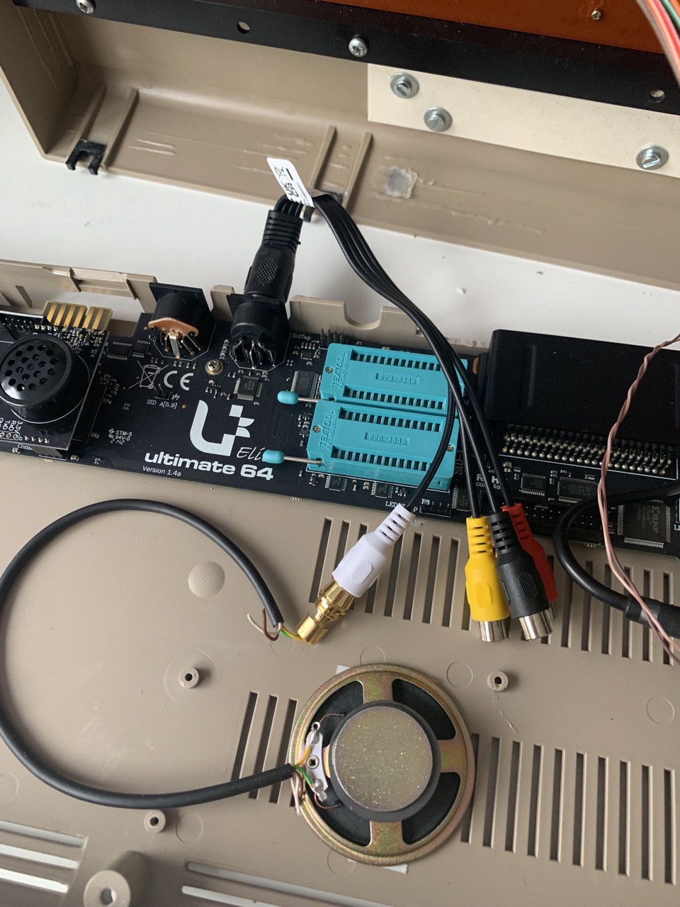
6Audio?
Unfortunately, the lacking audio output is the only shortcoming of the otherwise perfect retro display. So I'll need to think about a different solution.
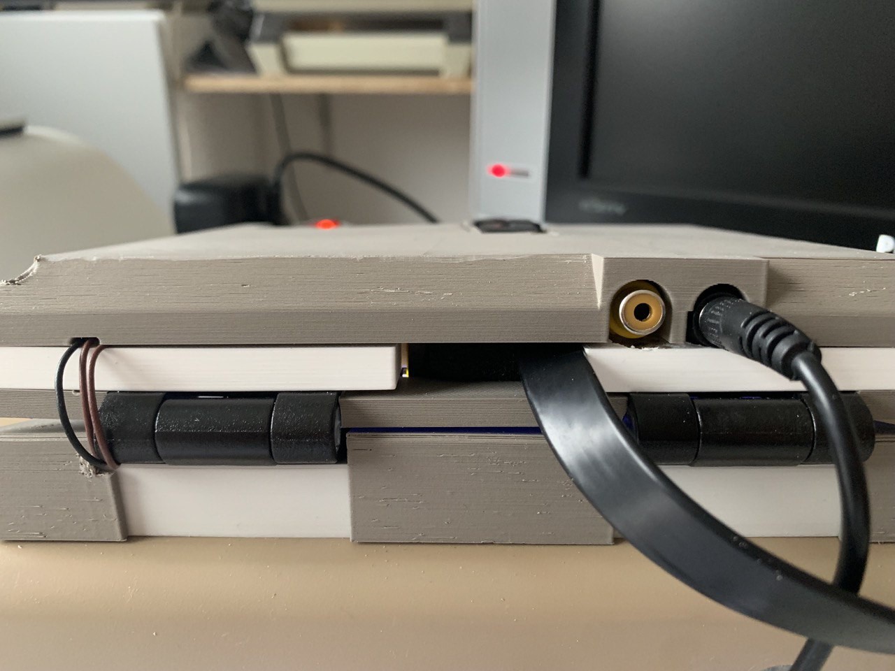
On the C64, the Audio/Video connector (among others) provides connections for Video-Out and Audio-Out on the DIN-plug.
![]()
What I did was just let the cable run inside the case and directly connect a speaker. However, this is unamplified, so it's hardly audible. Adding a small amplifier board with a knob for adjusting volume will be one of the next steps of this project.
However, this is how it works and this is how you can also do it. Of course, instead of connecting the speaker internally, you can always connect your big living room amplifier via cinch without any modifications to this. Just don't let the cable run into the case, but keep it outside.
Real C64 Cyberdeck
Evolve a real c64 into a portable decking device. Obsolete? Maybe. Useless? Definitely NOT.

Discussions
Become a Hackaday.io Member
Create an account to leave a comment. Already have an account? Log In.