This project is shelved (after only 12 logs?!!) and moved to #YGREC-РЭС15-bis, sorry for the inconvenience.
#AMBAP: A Modest Bitslice Architecture Proposal was meant to be a discussion about a bitslice-oriented architecture, not an almost-complete relay computer, so I moved it here!
The point of this project is to build a (somewhat) working computer without semiconductors (as functional/essential parts, see at the bottom of this page) that can at least "play" the Game of Life (see #Game of Life bit-parallel algorithm) on a Flip Dot screen and eventually process some numbers (outputing them to a dot matrix printer for example). Computer I/Os and basic GPIOs are considered too.
My goal is totally ridiculous but "it's for education purposes" because who would use a 25IPS computer (that's 25 instructions per second !) that draws hundreds of Watts ? I would like to see how it was possible to build a decent system with the technology of the 40's (Konrad Zuse and others will be proud of me). However there is more to this because it will be the first physical implementation of the methods and ideas of AMBAP !
Logs:
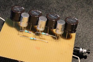
1. Capacitors and diodes
2. Clock generator
3. Dual Diodes (the hard way)
4. Output TTY
5. CC-PBRL : Magnetic hysteresis and fanout
6. Power-On routine
7. Parity or not parity ?
8. New DRAM array
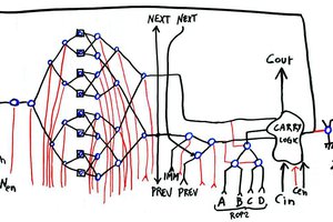
9. Structural sketches
10. More balanced trees !
11. Architecture update
So far, the features are:
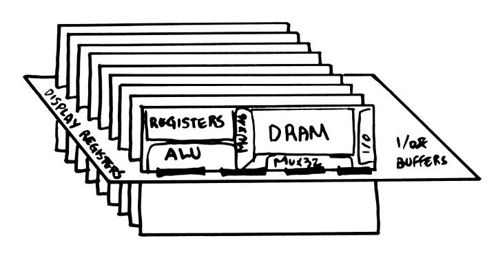
- 16-bits datapath made of 16 identical "processing" boards (each is one "bitslice") with a) register set b) ALU c) data memory (actually, 2 more boards are needed to provide parity protection)
- About 3000 relays :
- 1000 for the RAM (row&column decoders of DRAM),
- 500 for the register set,
- 500 for ALU,
- 500 for instruction fetch and decoding,
- another 500 for I/O...
- Expected speed : about 20 to 30 instructions per second (hopefully 25 but the memory system might slow things down). AMBAP is very RISC-style so "instruction" means ROP2, ADD/SUB/CMP or single-bit shift, with eventually one memory access in parallel. To be determined and confirmed.
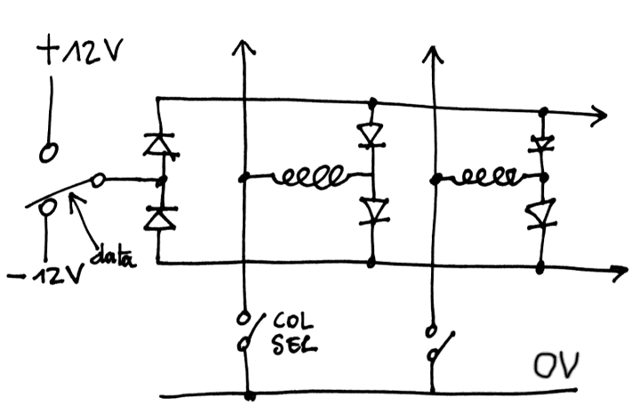
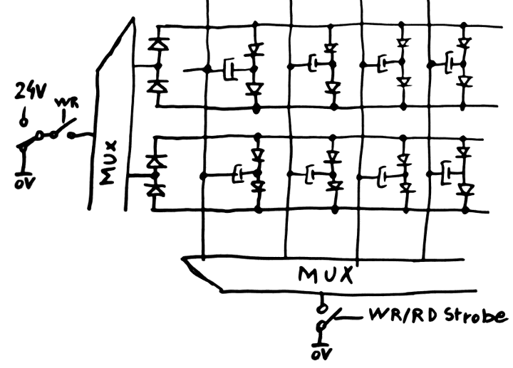
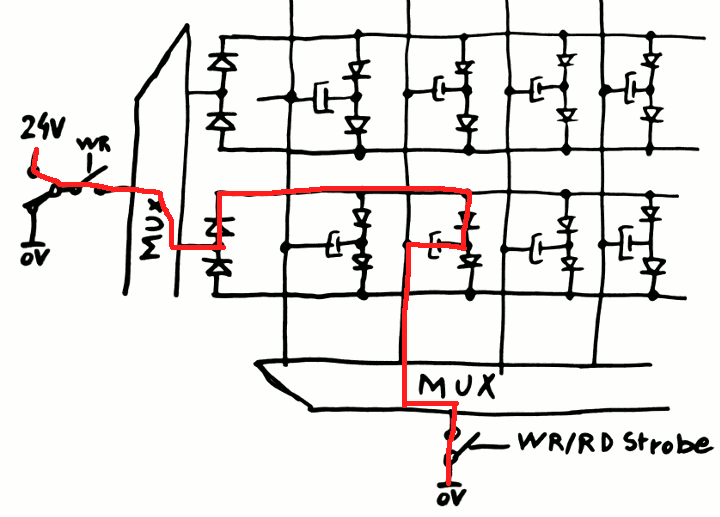
- 512 words of DRAM, made of 9200 capacitors (and 18K diodes). The refresh circuit uses idle memory cycles, when the processor does not access the Data Memory Bus.
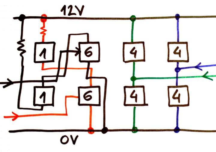
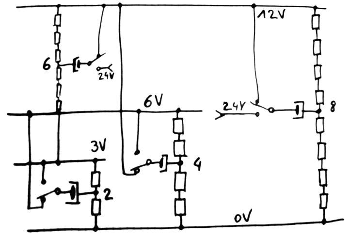
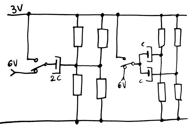
- Uses РЭС15 (low-voltage russian SPDT relays) with the specially-developed CC-PBRL topology (Capacitive-Coupled Pre-Biased Relay Logic) with 3.3V, 6V and 12V domains. This enables higher power-efficiency and lower ripple on the power supplies.
- Power supplies are symmetrical : 0/12V/24V for the high-fanout signals, and 0V/3.3V/6.6V for the simpler logic parts. Relays are great at jumping from one power domain to another :-) The higher voltage is usually less loaded and requires a smaller power supply but more decoupling for the transients (or so I thought, until I counted all the high-fanout signals...).
- Display through a (memory-mapped) Flip-Dots Luminator matrix. You can spy the activity in real time and see the stack as it updates, for example. Or play Tetris or #Game of Life bit-parallel algorithm.
- Programming model / ISA : 8 registers, including 4 "normal" registers and 2 pairs of "address/data" for register-mapped memory access. It's a very basic RISC architecture without the load-store part. Like ARM there is a small shifter in front of the ALU (which is incredibly handy for the Game of Life code).
- Programming : using diode ROM, either soldered or with DIP switches... Several programmable cards should be built.
- PC is separate and (unlike #YASEP Yet Another Small Embedded Processor) requires dedicated JUMP instructions (not considered or evaluated yet).
- I/O through an expansion board and explicit instructions (later, one day). Or might be memory mapped, who knows.
The instruction format is not defined yet. I'll design it on the go but it will be mostly control signals for all the circuits. RISC ideas make it pretty straight-forward. The method is to first design the "datapath" (registers/ALU/Memory)...
Read more » Yann Guidon / YGDES









 Stefano
There has been a great deal of value to me in my involvement with the project. Would like to share it with the CPS Tester team so they can also read it and implement something new.