Timo
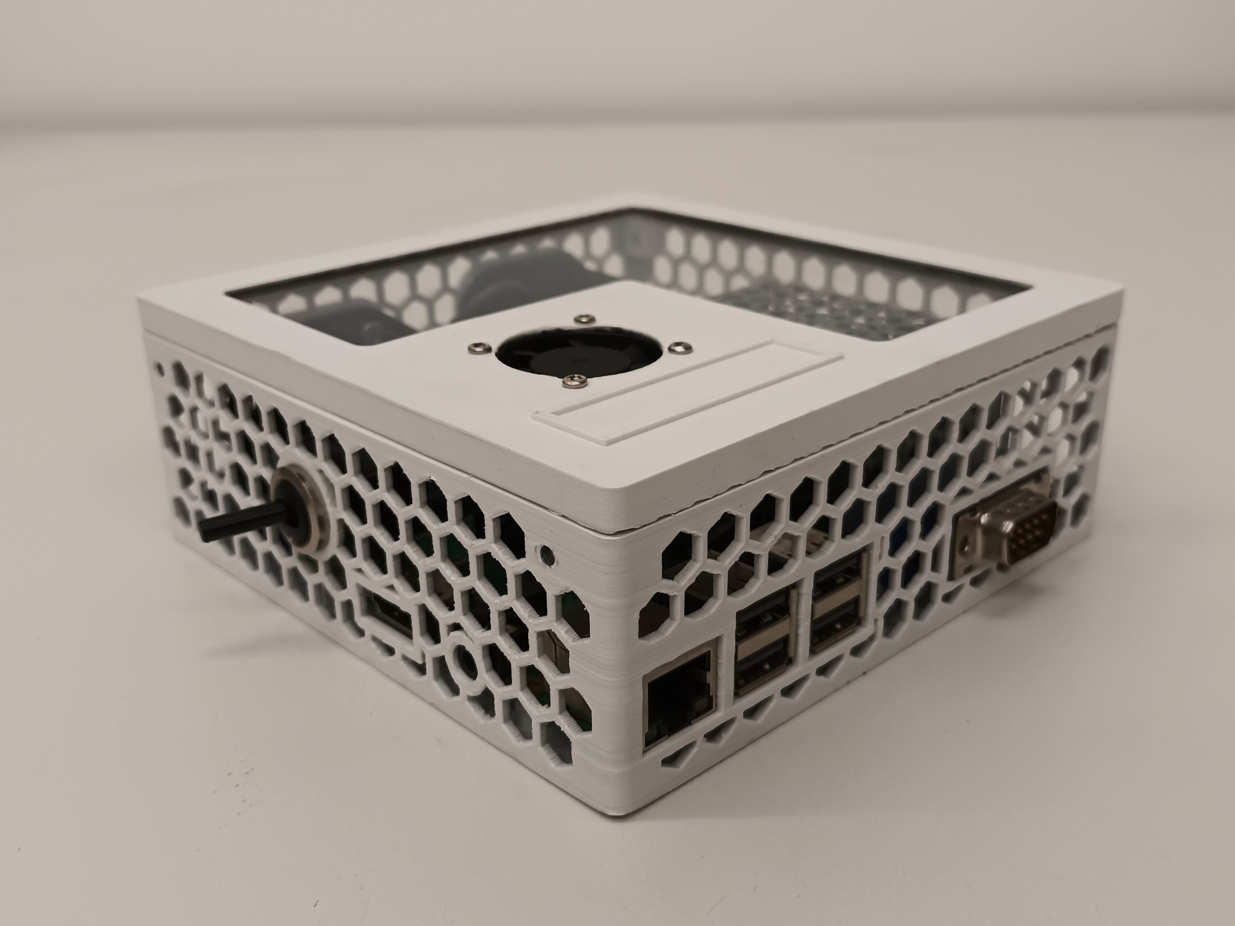
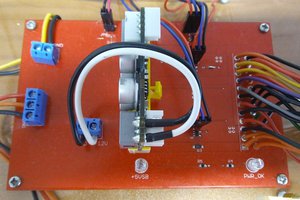
TimoThe picture shows the Raspberry Pi and my carrier board.

The main features of the carrier board are an RS232 driver, a fan header and the power supply.
Fan Header
Although the case lets lots of air inside, the CPU gets warm up to 50°C in idle. The fan can be controlled by the RPi via a GPIO. I set up a program which starts after booting the OS. It reads the CPU's temperature and sets the fan speed so, that the CPU's temperature is 35°C..
Power Supply
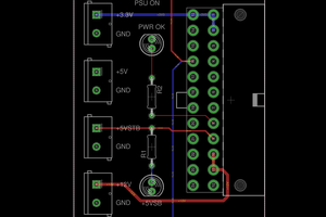
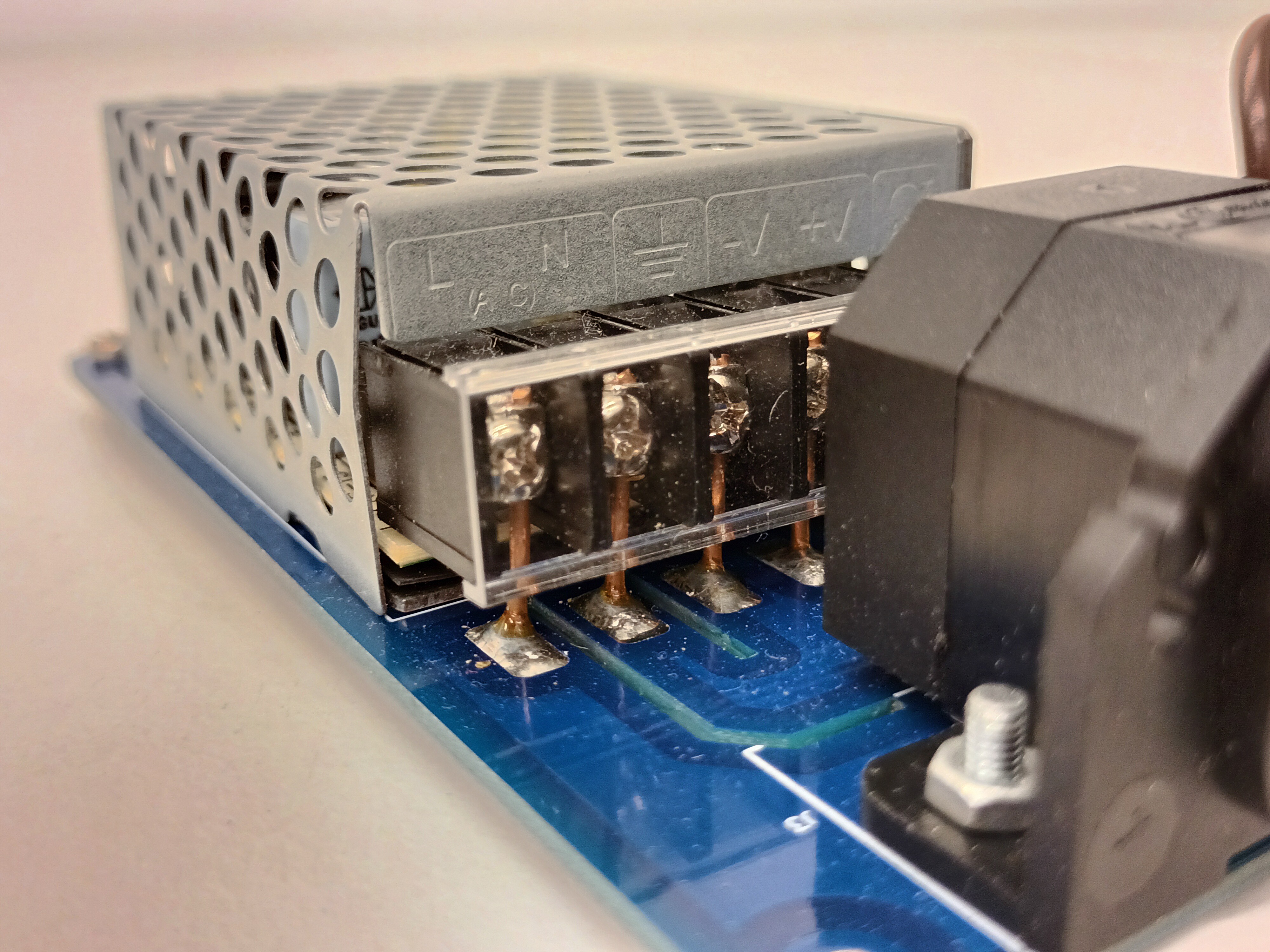
+5V power is provided by a closed frame power supply which can source a current of 3A which is plenty for the Pi. The supply can be completly separated from mains voltage via a switch, so no standby power is drawn. Additonally main voltage is passed through the switch to a second connector, which in turn is used to power the monitor.
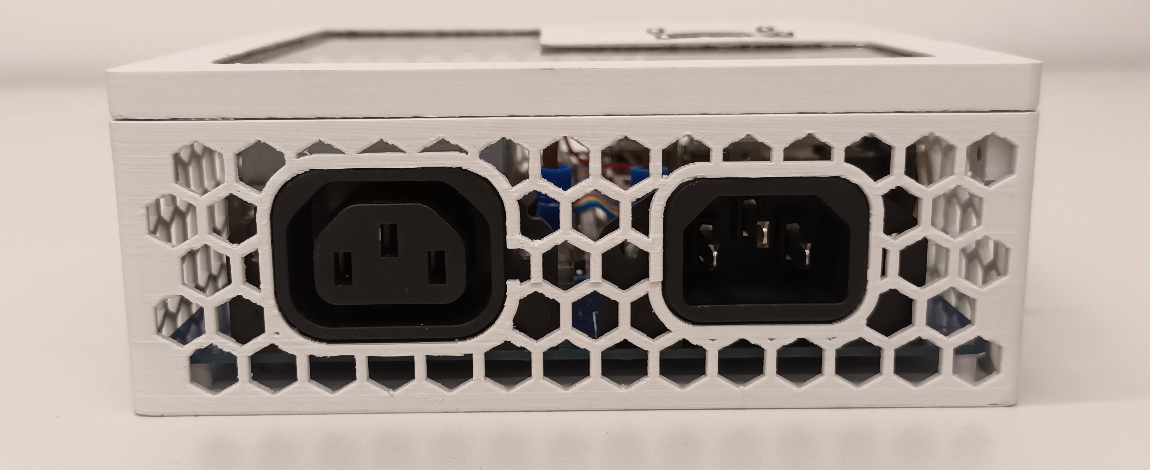
So after powering down the RPi, power can be disconnected from workstation and monitor by just one switch. Also just one flip of the switch turns on the hole system.
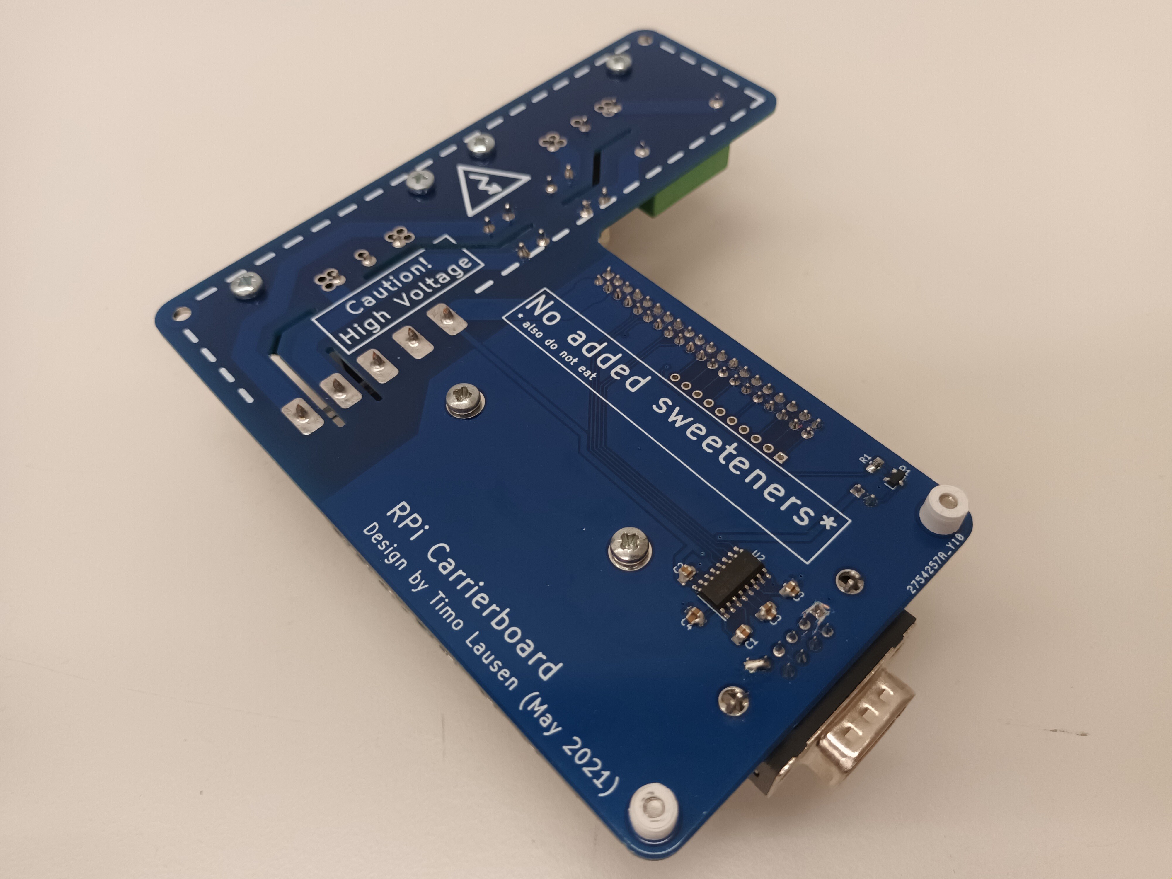
PCB
A view of the nacked carrier board.
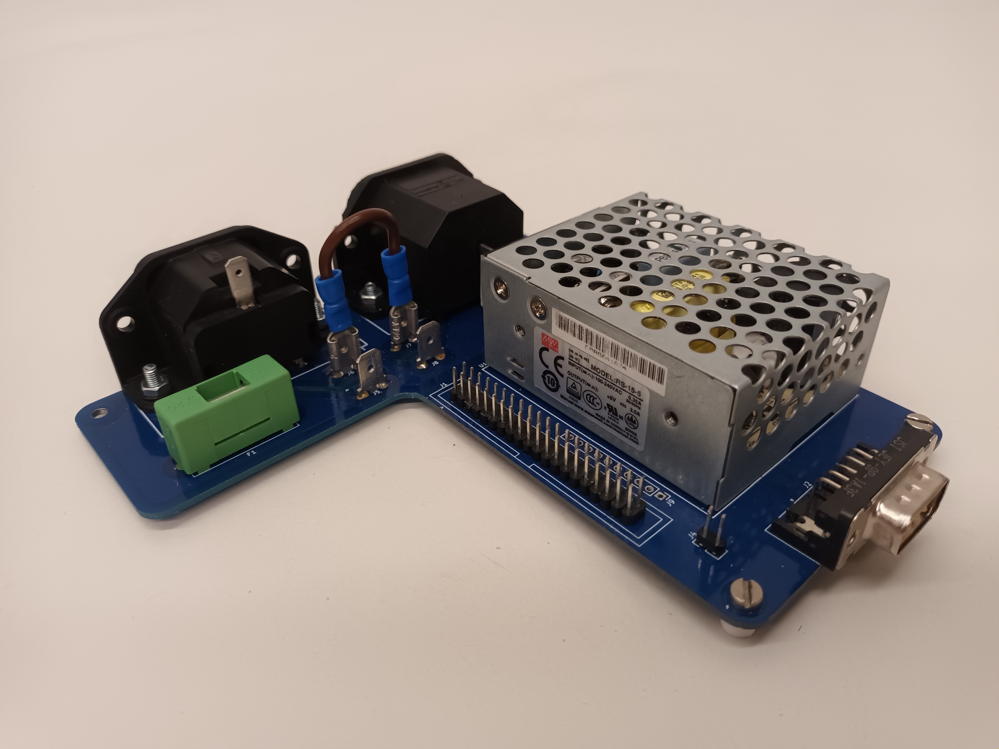
The closed frame power supply is screwed onto the pcb. Short wires are soldered into the pcb and connect the screw terminals of the power brick.
 Dave's Dev Lab
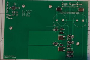
 NuclearPhoenix