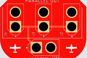
To use it, remove the SOT-23-5 linear regulator `U7` from the board and solder the replacement to the two outer-most pads of the 3 pads on the bottom. The middle pad on the bottom and the two pads on top will not be soldered. Then solder a wire to the power switch pad labeled `C` and the pad on your replacement part. That's it! The PCB fits very nicely in there and is held on by the two pad connections to the main PCB of the GBC.
While you're at it, replace the electrolytic caps `C32`(100µF, 6V), `C35` (22µF, 16V) and `C38` (100µF, 4V) on the bottom portion of the main PCB near the batteries with new ceramic or tantalum caps.
That's it, have fun!
 NuclearPhoenix

 Dave's Dev Lab

 Timo
Timo