Solder the 40 pin female connector to the BCI2103 pcb.
Cut a 6 foot piece of 25 conductor 20 awg cable. The CF5-05-25 cable has numbered wires.
Remove 4 inches of sheath from one end and 6 inches from the other.
At the end with 6 inches of sheath removed, strip wires 1-24 leaving 1/4 inch of bare copper.
Attach the 33001-3004 terminals to wires 1-12.
Attach the 33011-0004 terminals to wires 13-24.
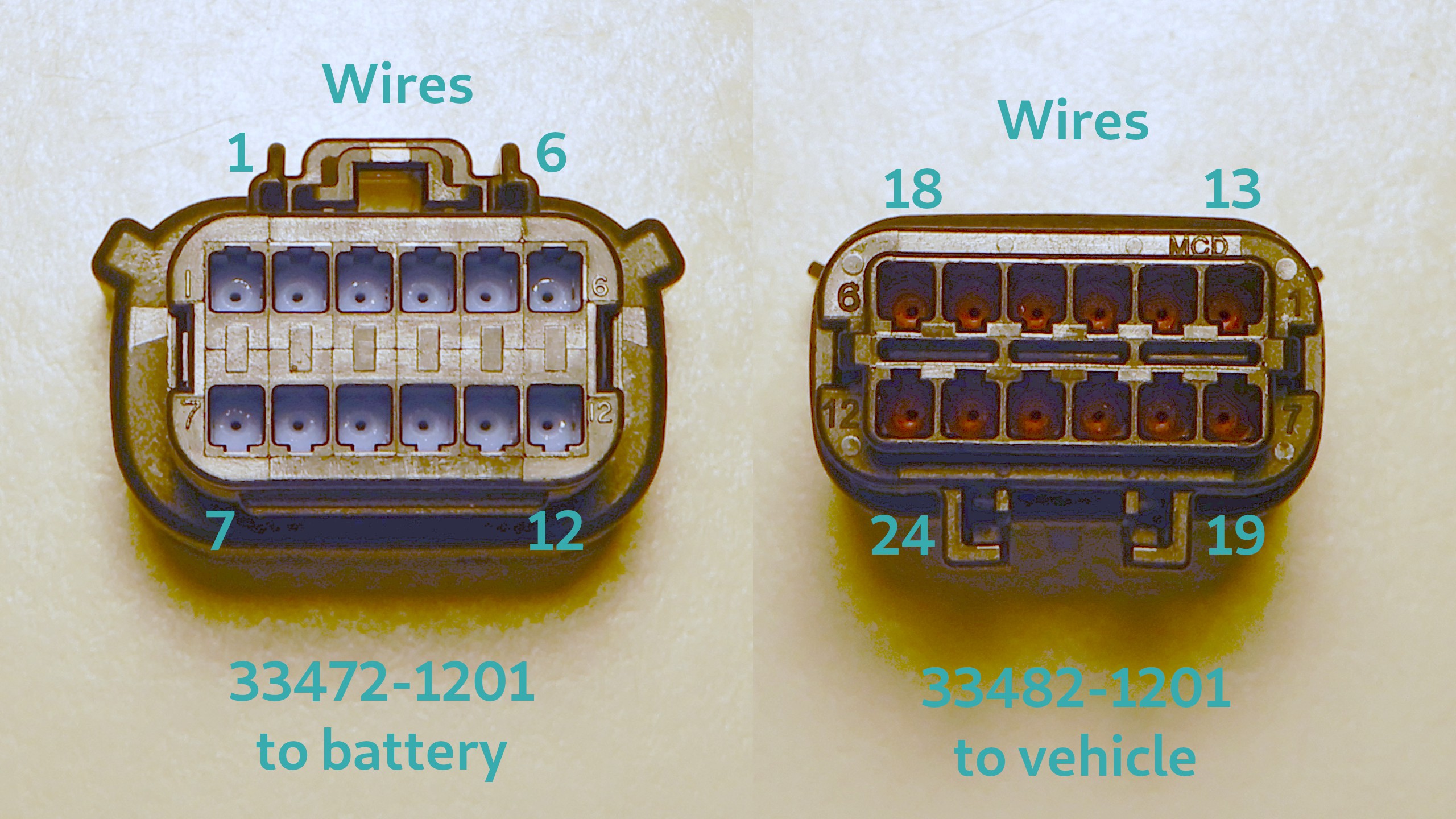
Insert the wires into their numbered positions. Since the connectors are numbered 1-12 and we are connecting two connectors to one cable, the numbers for the second connector are offset by 12. Note the ordering differs between the connectors.
Slip a cable gland over the cable from the other end which has 4 inches of sheath removed. The exterior end goes towards the connectors. The interior end goes towards the wires.
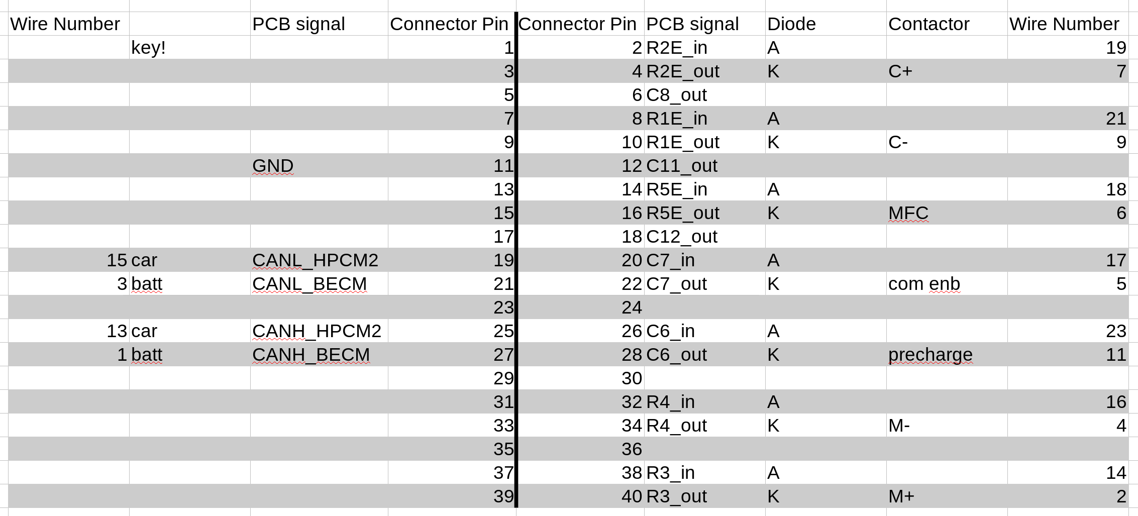
Solder the wires to a BCI2103F pcb according to the wire numbers shown. It might be best to cut, strip, and solder one wire at a time. Some wires remain unconnected. They are needed only to seal the connectors from water.
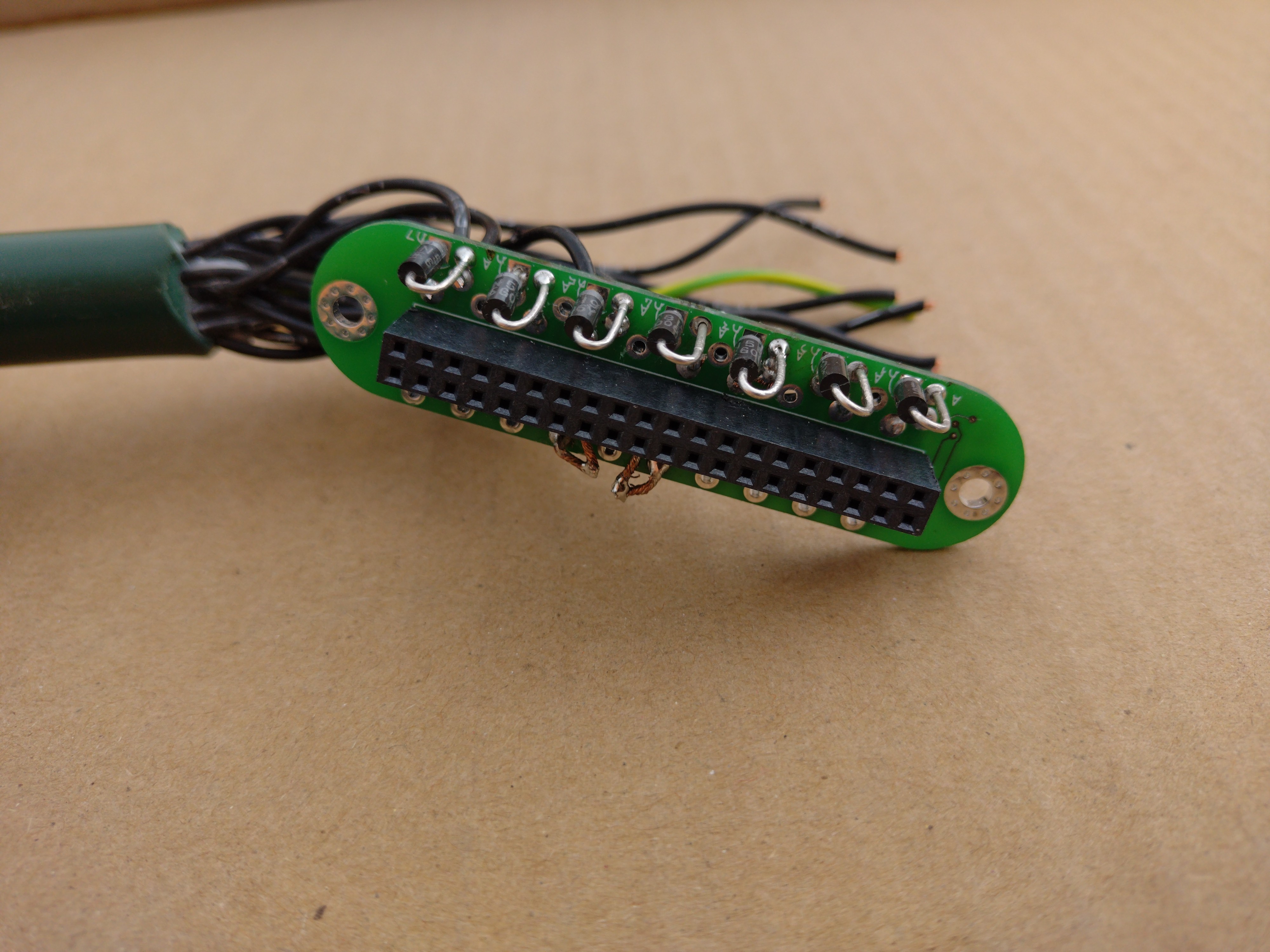
Solder the 1N5819 diodes.
Connect the two connectors together and check for continuity across the diodes.
Add a small jumper wire or solder bridge to connect the two CANL lines together. And connect the CANH lines together as well. This will ensure the most reliable operation since there is no software to make use of the CAN bridge feature yet. The jumpers allow CAN data to pass through the cable even if the 40 pin connector is disconnected. The diodes allow the contactor control signals to pass through from the vehicle to the battery pack.
Wrap the connector end with electrical tape for protection.
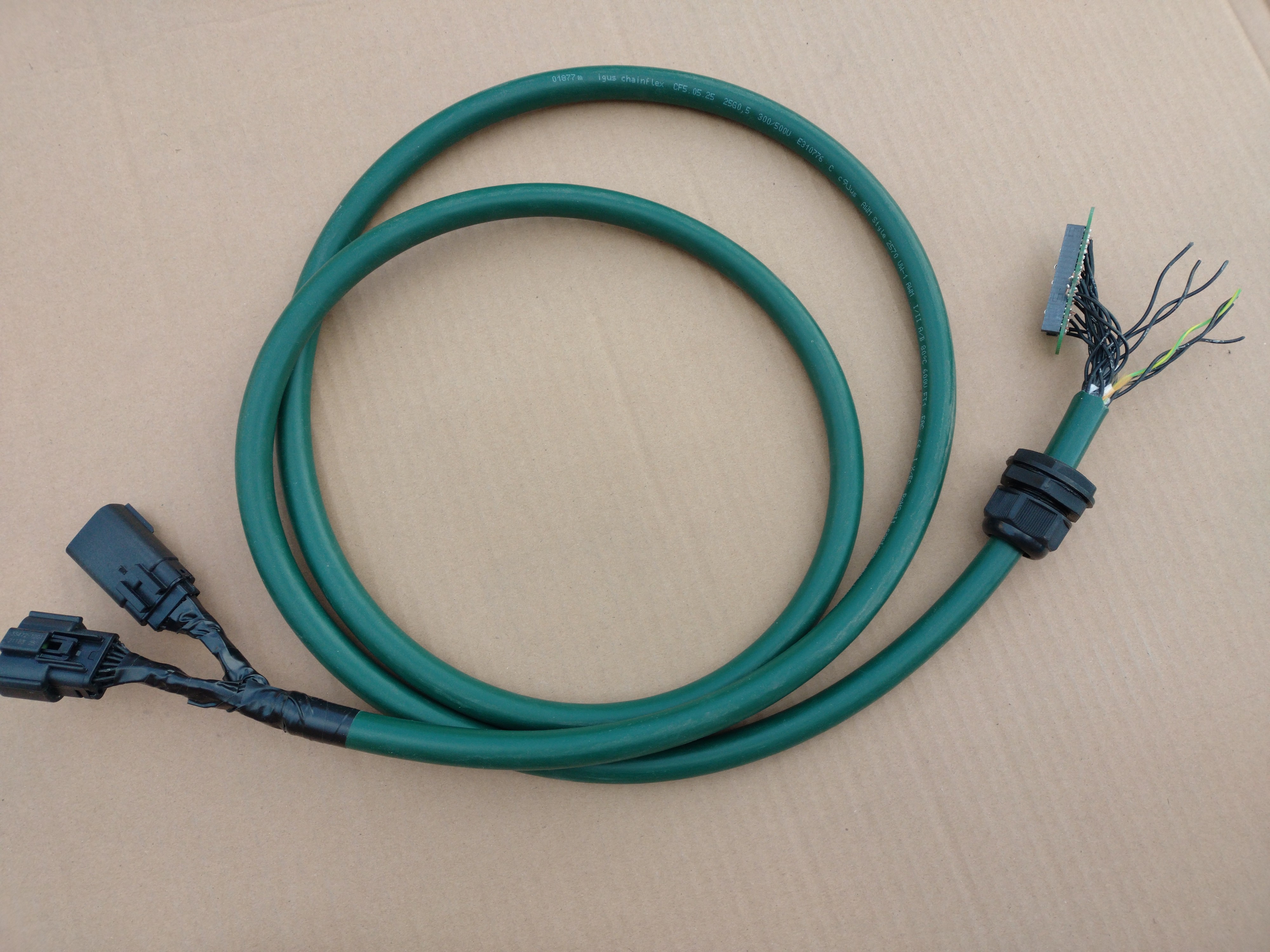
Overall view of the completed cable assembly.
2
Installing the Battery Interface Cable
Raise the vehicle on a lift or ramps and jack stands.
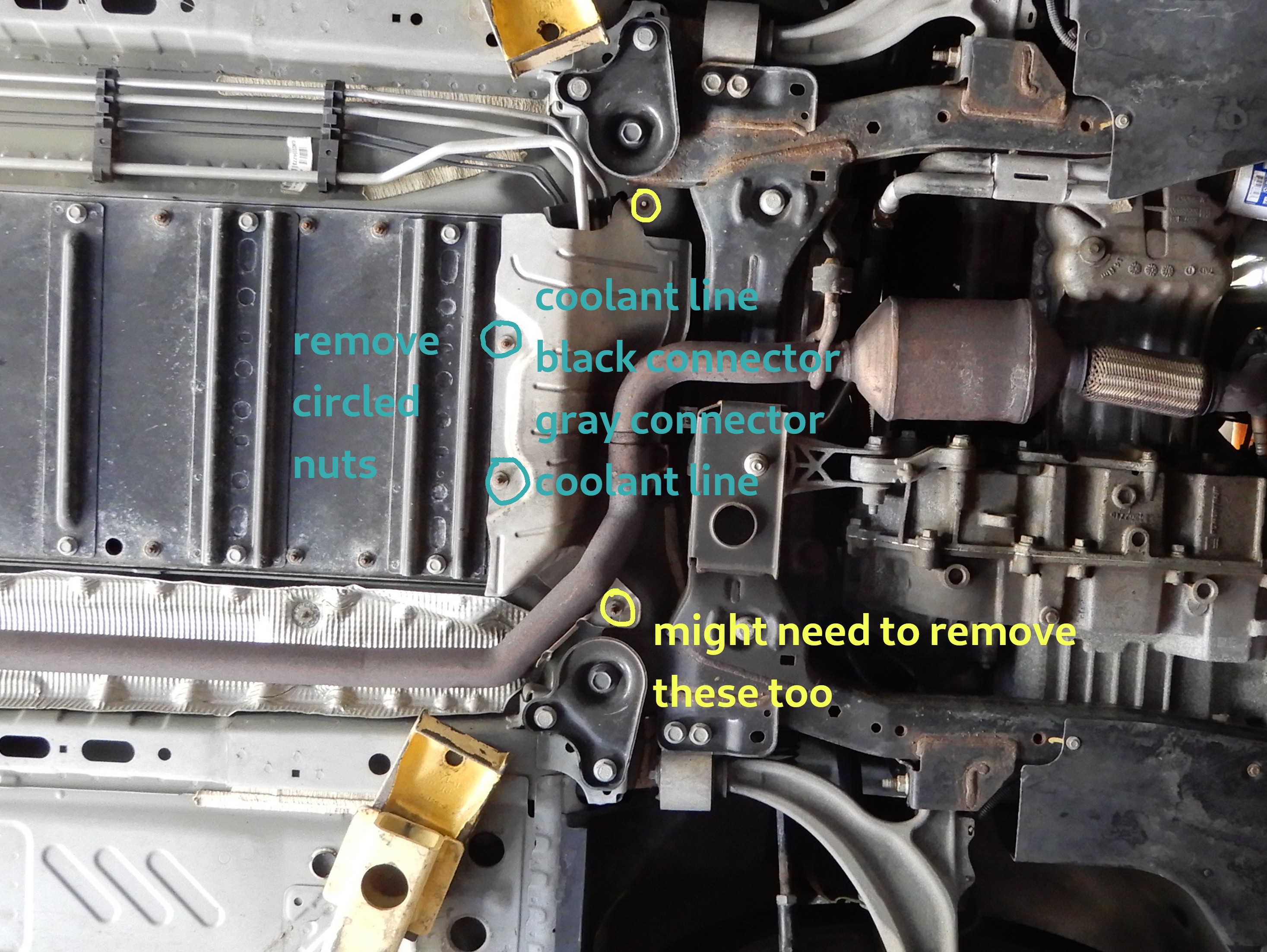
Remove the blue circled nuts on the heat shield. It's common for these bolts to break, so we will try to not remove all of the heat shield bolts.
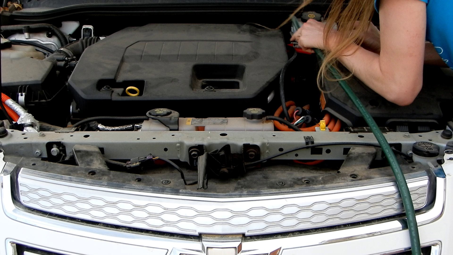
Fish the Battery Interface Cable down from the top. Connector end goes down. Use the main high voltage supply cables to the inverter as a guide.
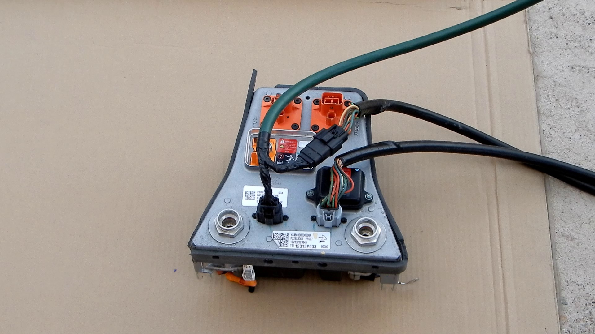
Unplug the black connector from the battery. Connect the Battery Interface Cable to the matching connectors on the battery and vehicle wiring harness. This connection is shown on a spare contactor module for clarity.
Reinstall any nuts removed from the heat shield.
Wrap the PCB end of the Battery Interface Cable with an insulating material to prevent the diode leads from shorting to other underhood components.
3
Mounting the solar panels
Install the Yakima Jetstream roof racks according the instructions.
Get 8x 8"x7/8" bracket, 4 for each solar panel.
File out the end hole to fit the square part of a 1/4"x1" carriage bolt.
Drill out the next hole to fit the round part of a 3/8"x1" carriage bolt.
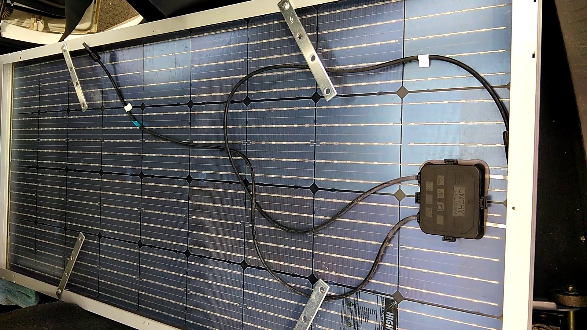
Slide a 1/4"x1" carriage bolt through the bracket and through the frame of the solar panel. Secure with a washer and nut inside the panel frame. It should be tight enough that bracket can be easily rotated by hand but tight enough that it does not rotate under its own weight.
Orient the brackets like shown.
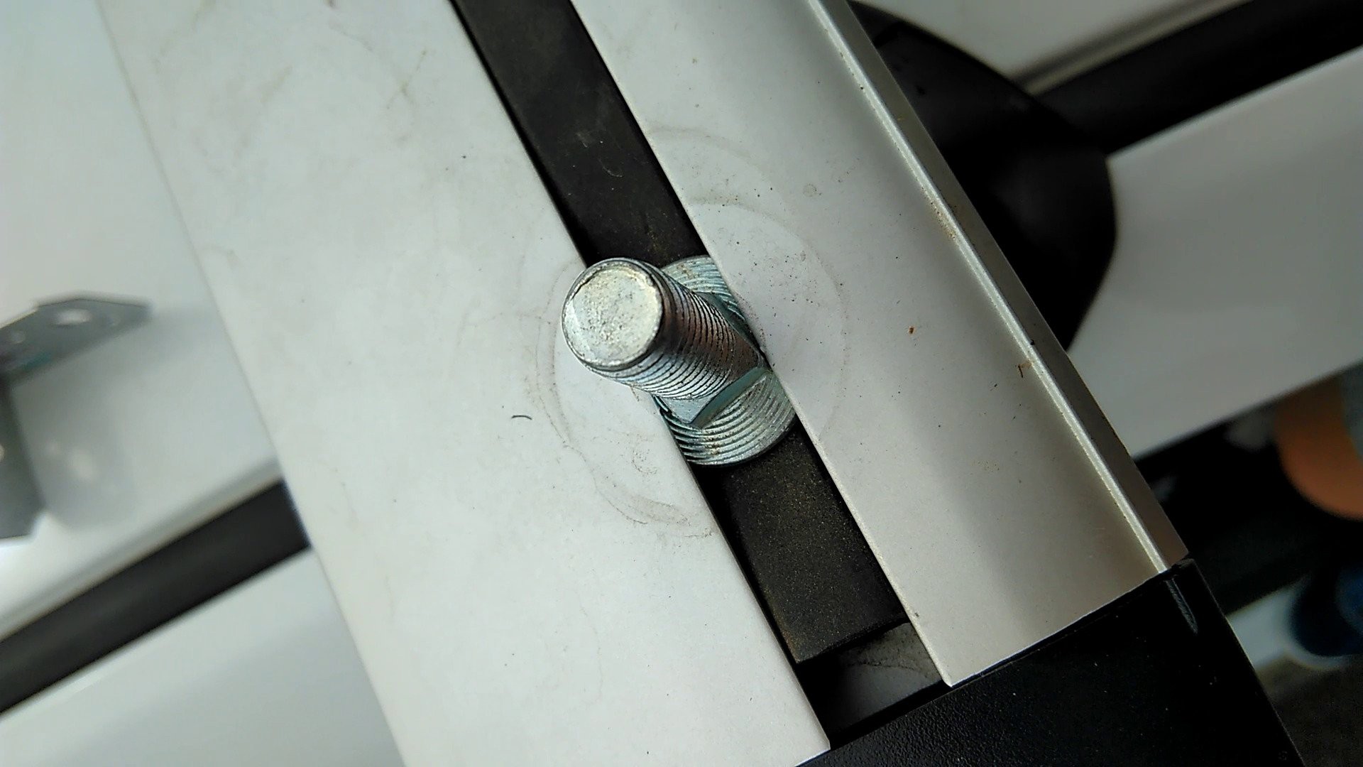
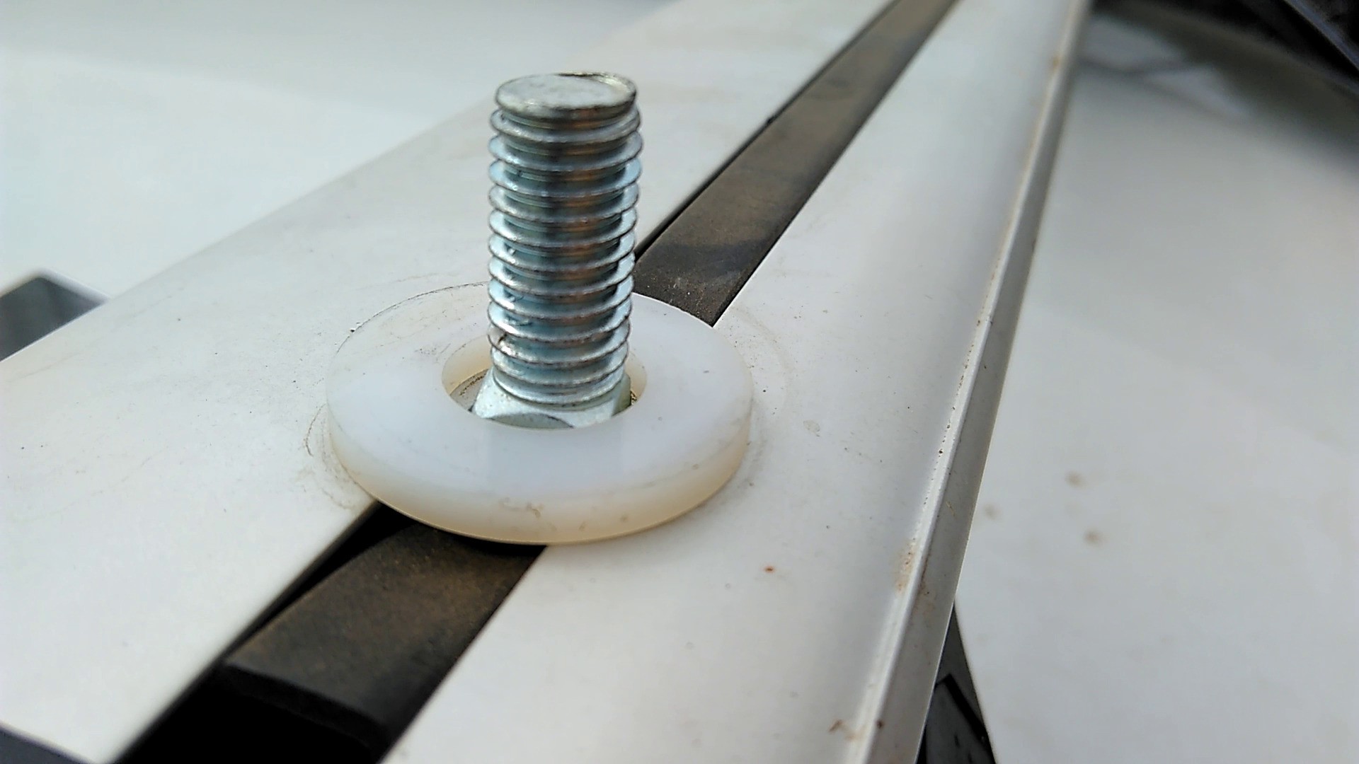
Slide 4x 3/8"x1" carriage bolts through the channel of each roof rack bar. One bolt towards each end of the bar and two bolts near the middle.
Place a 1-1/8"x0.54"x1/8" nylon washer over each carriage bolt. The washers should sit flush on the roof rack bar.
Carefully lower each solar panel onto the carriage bolts. The bolts can be slid along the channel and the brackets rotated to find the right positioning.
Carefully open the hatch to check for clearance between the hatch and the solar panels.
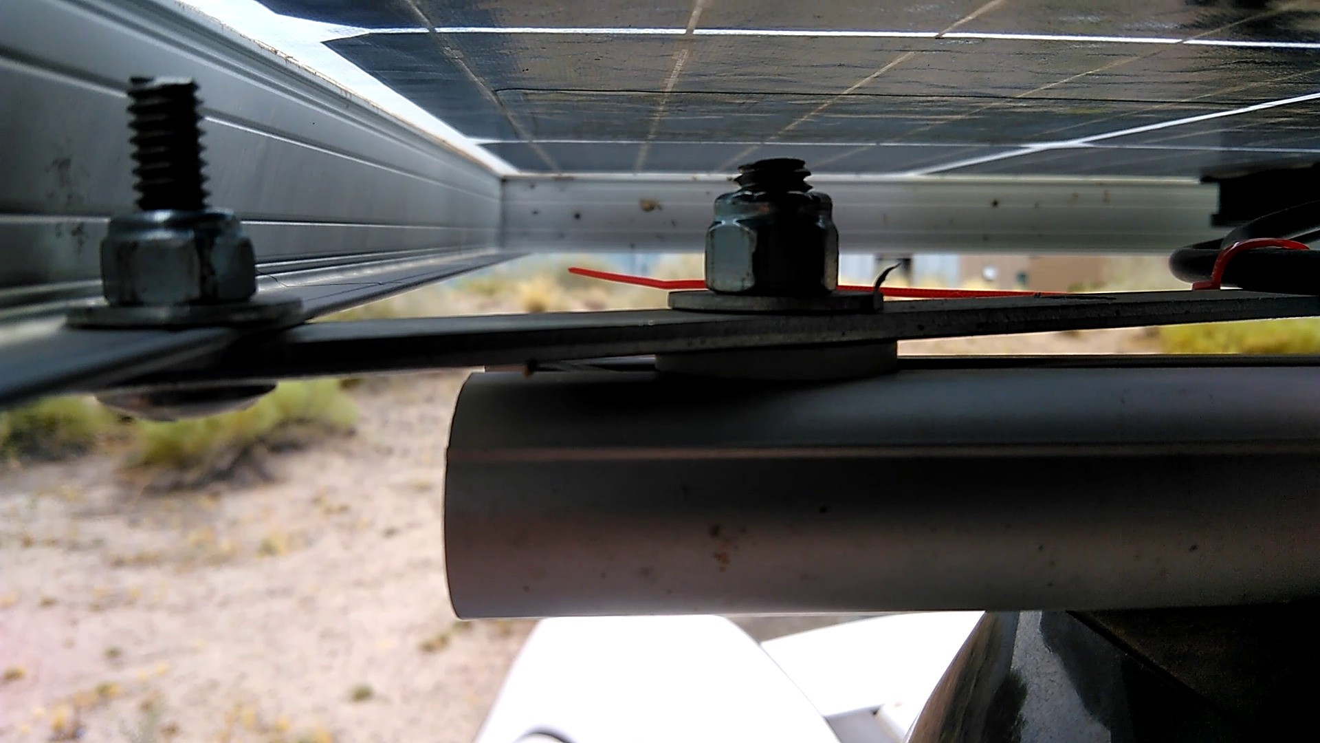
Secure the solar panel brackets with a washer and nut.
Tighten all nuts firmly. Remember to tighten the nuts inside the solar panel frame as well.
Cut a piece of 14/4 SJOOW cable to reach from the solar panels to the mounting location of the DC-DC charger board.
Attach MC4 connectors to one end of the cable.
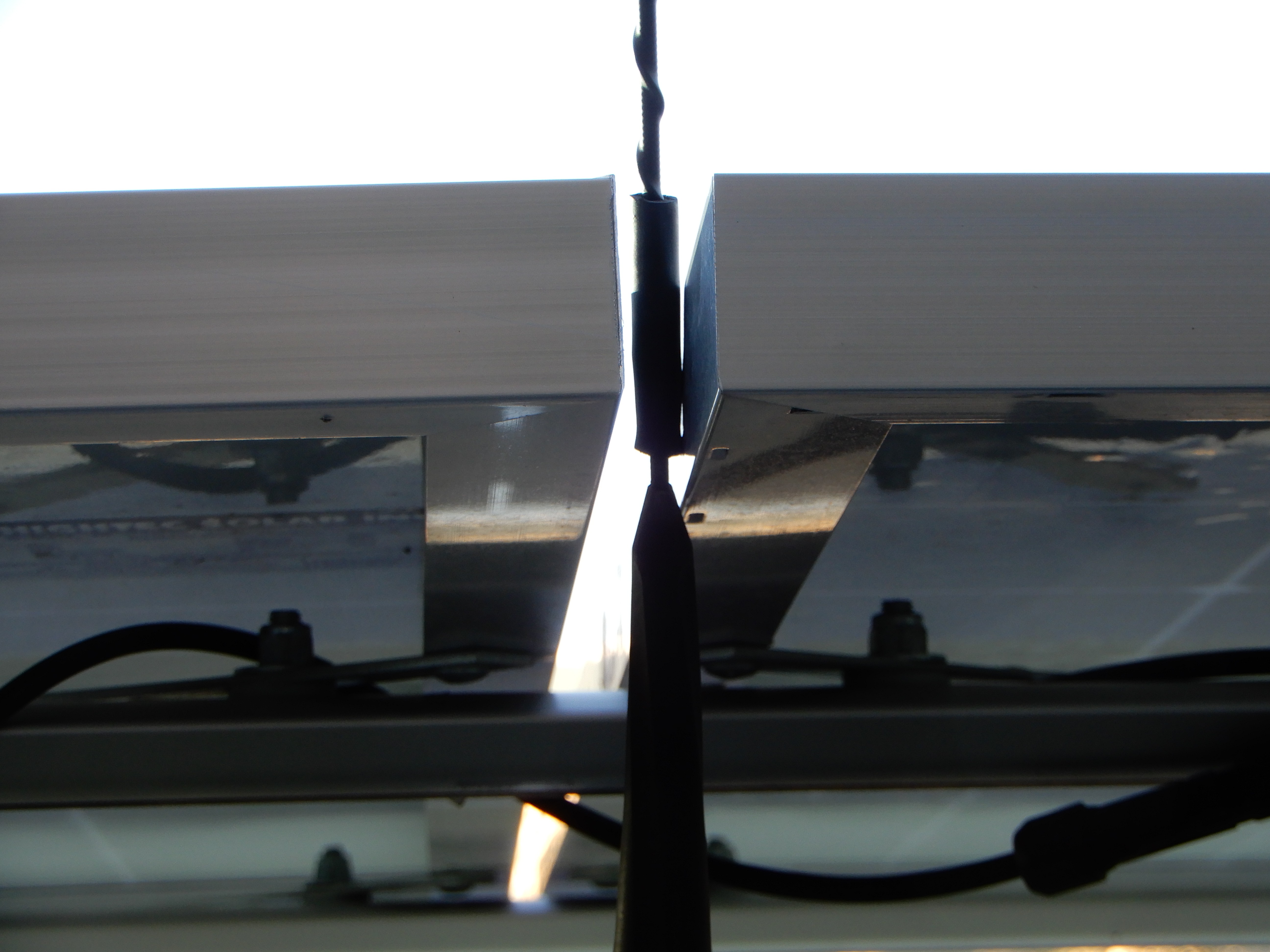
Route the cable under the solar panels but above the roof racks, then down the side of the windshield. Keep it towards the outside of the wiper pivot and run underneath the foam block where an existing wiring harness runs.
Optional: Slide a 2" piece of 14/4 SJOOW cable sheathing over the radio antenna to prevent antenna wear against the solar panels.
The PCDB2105 was designed for a 72 cell solar array. Since these are 36 cell "12v" panels, connect them in series.
4
Building the HV Interface Cable for G1 Volt
This is the trickiest part because the high voltage high current EV coaxial cable is not available to consumers. And the HV connectors are nearly as difficult to get and figure out what parts you need. I used a 4 conductor cable to keep a ground wire near the HV power even though it was not a coaxial shield or twisted pair.
Acquire a Chevy Volt AC compressor and HV accessory cable from a junkyard or online.
Cut the HV connectors off, leaving about 18 inches of cable attached.
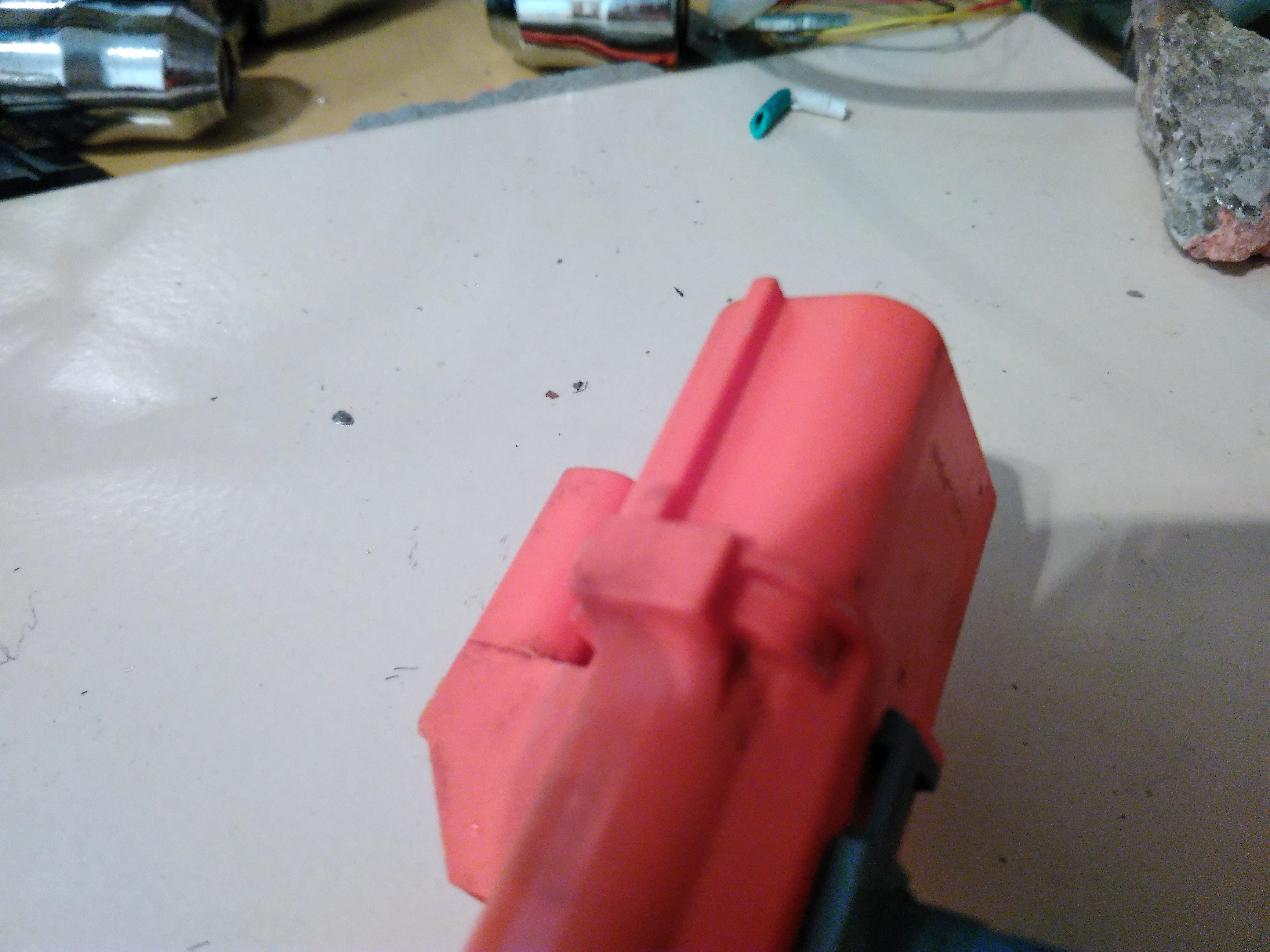
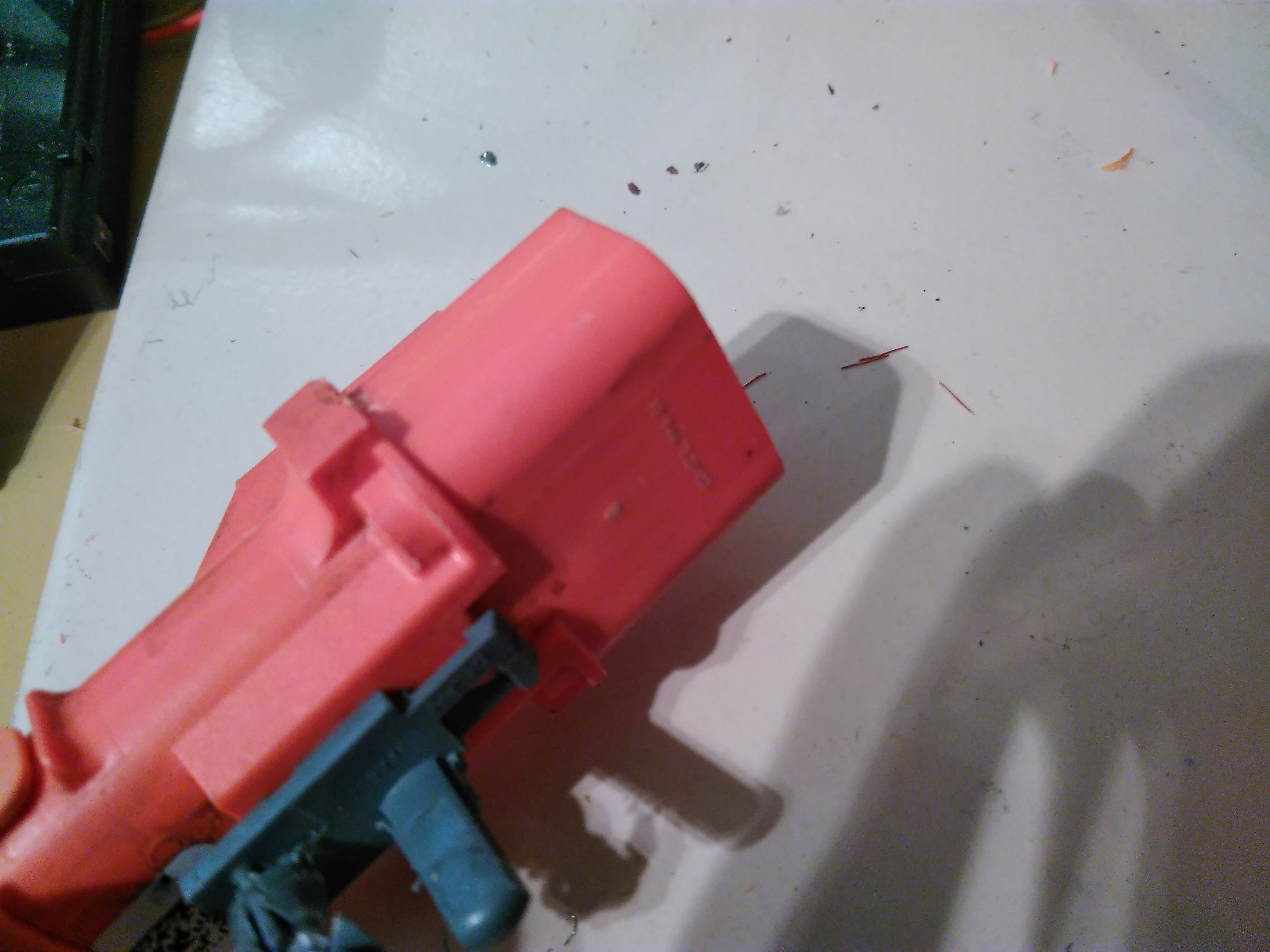
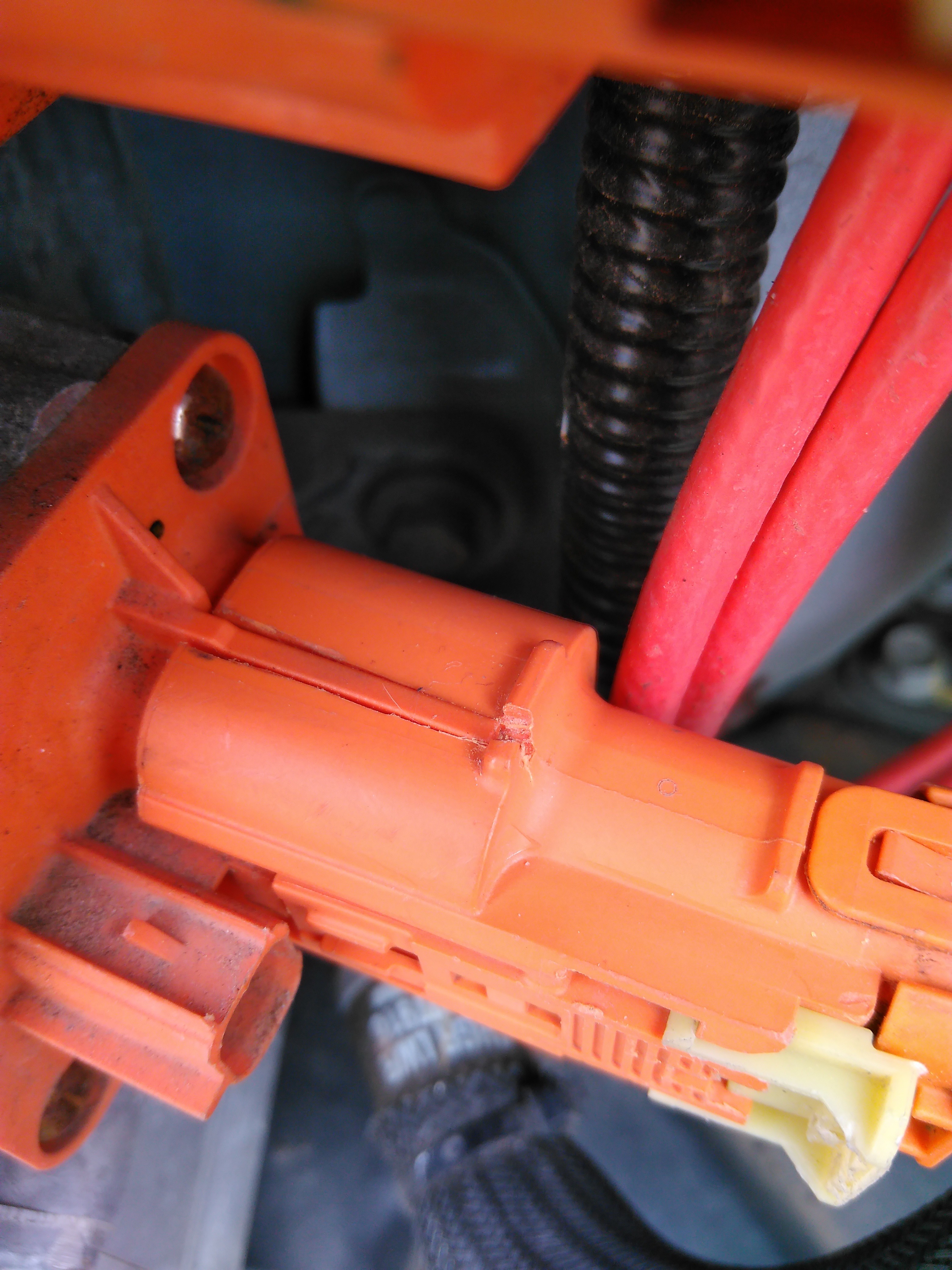
Shave off the key ridge from the side of the connector.
Cut a notch in the side of the other HV connector to allow it to slide onto the connector on the charger.
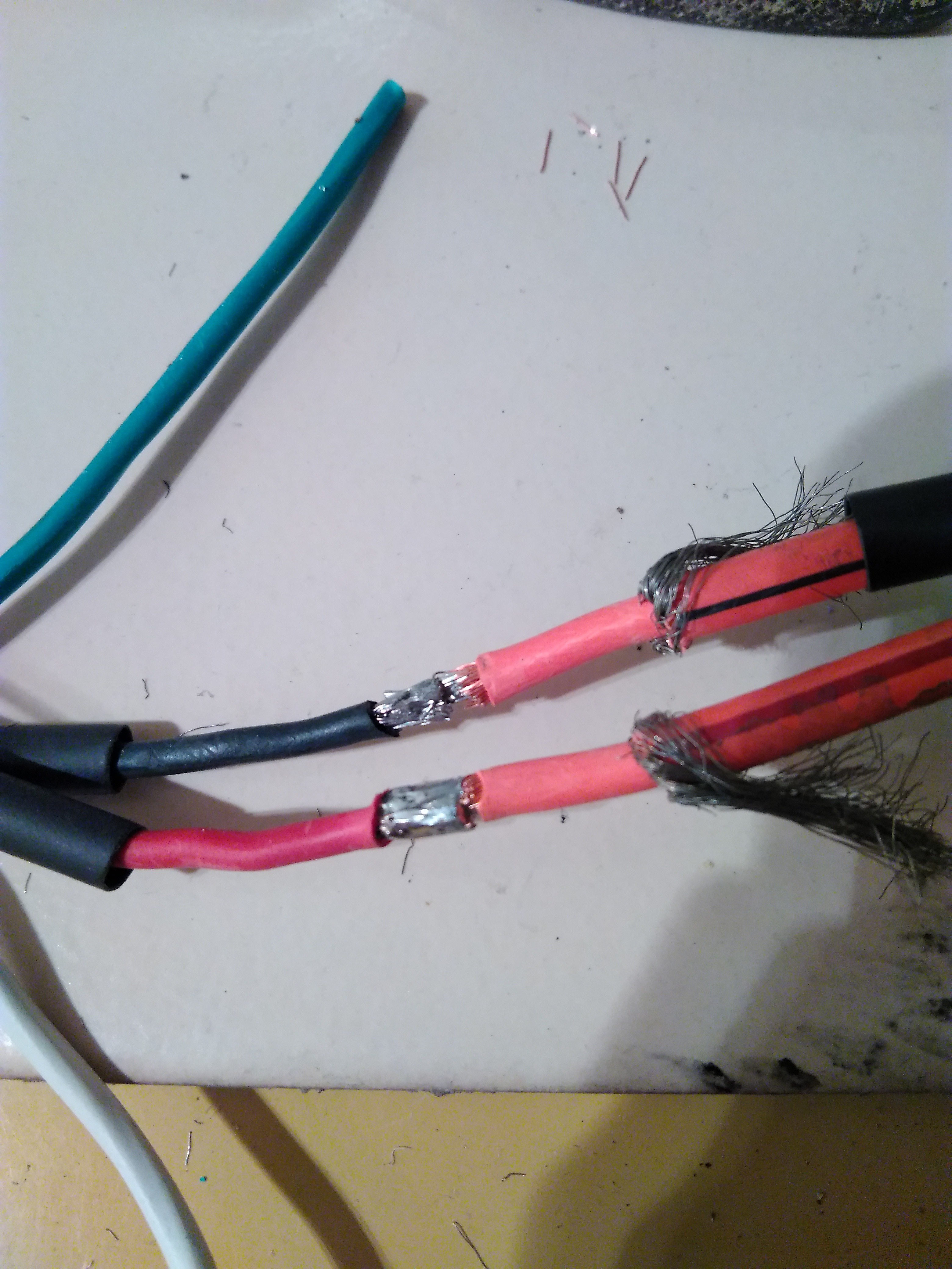
Strip about 1.5 inches of the outer insulation.
Peel back the coaxial shield.
Strip about 0.5 inch of the inner conductor.
Before soldering, slide a generous amount of marine grade heat shrink tubing over the wires.
Cut two 6 foot pieces of 14/4 SJOOW cable. Strip one end to 1/2".
Solder the red and black wires to the inner coaxial conductors. Look for a red or black stripe on the exterior insulation.
Connect the HV connectors together and test for continuity from red to red and black to black.
Slide heat shrink over the inner conduction joints and shrink.
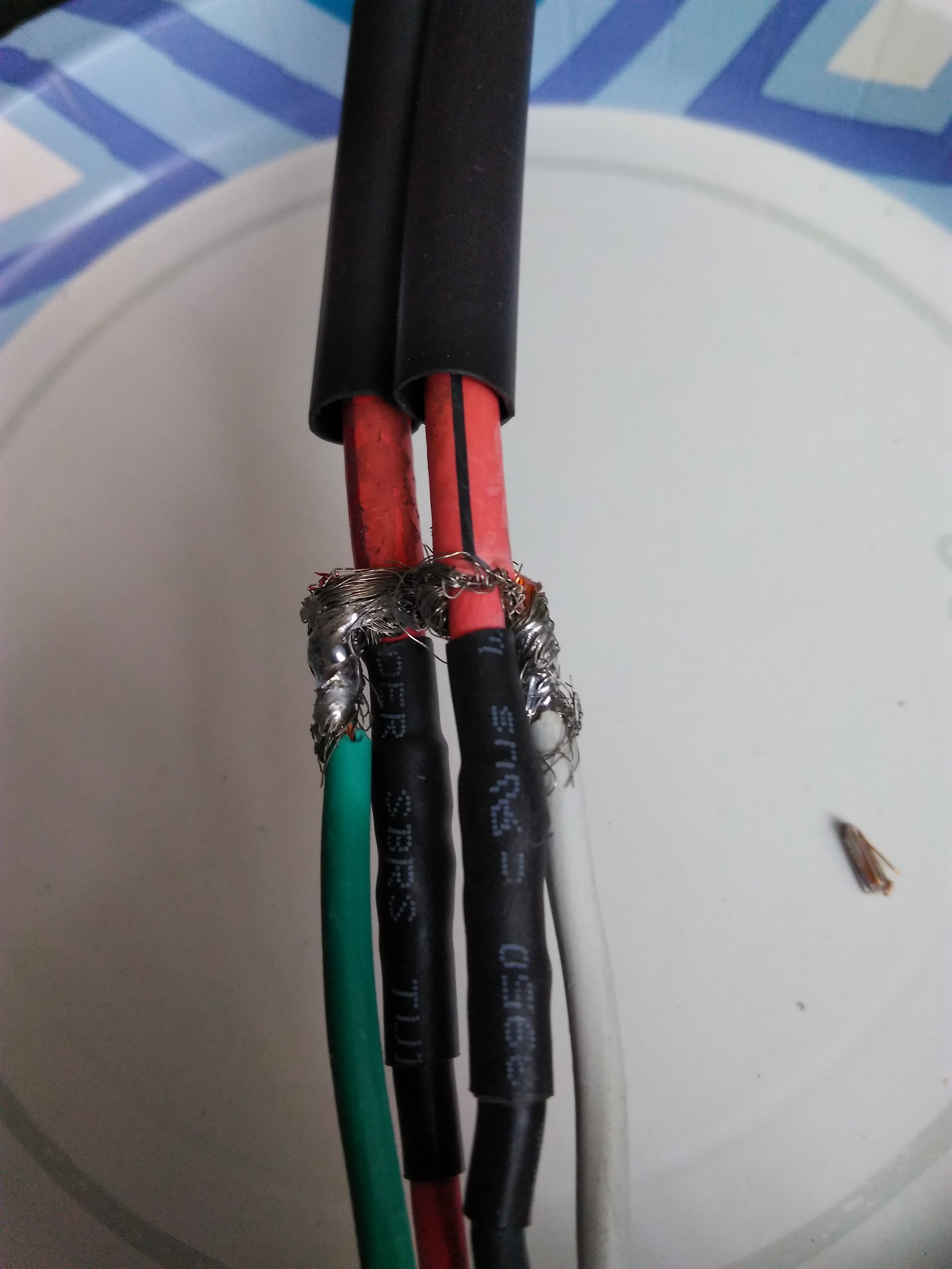
Solder the outer shield to the other wires in the SJOOW cable.
Cover these joints with heat shrink.
Terminate the HV power wires on the other end of the SJOOW cable with MC4 connectors.
Solder the shield wires directly. Cover with heat shrink.
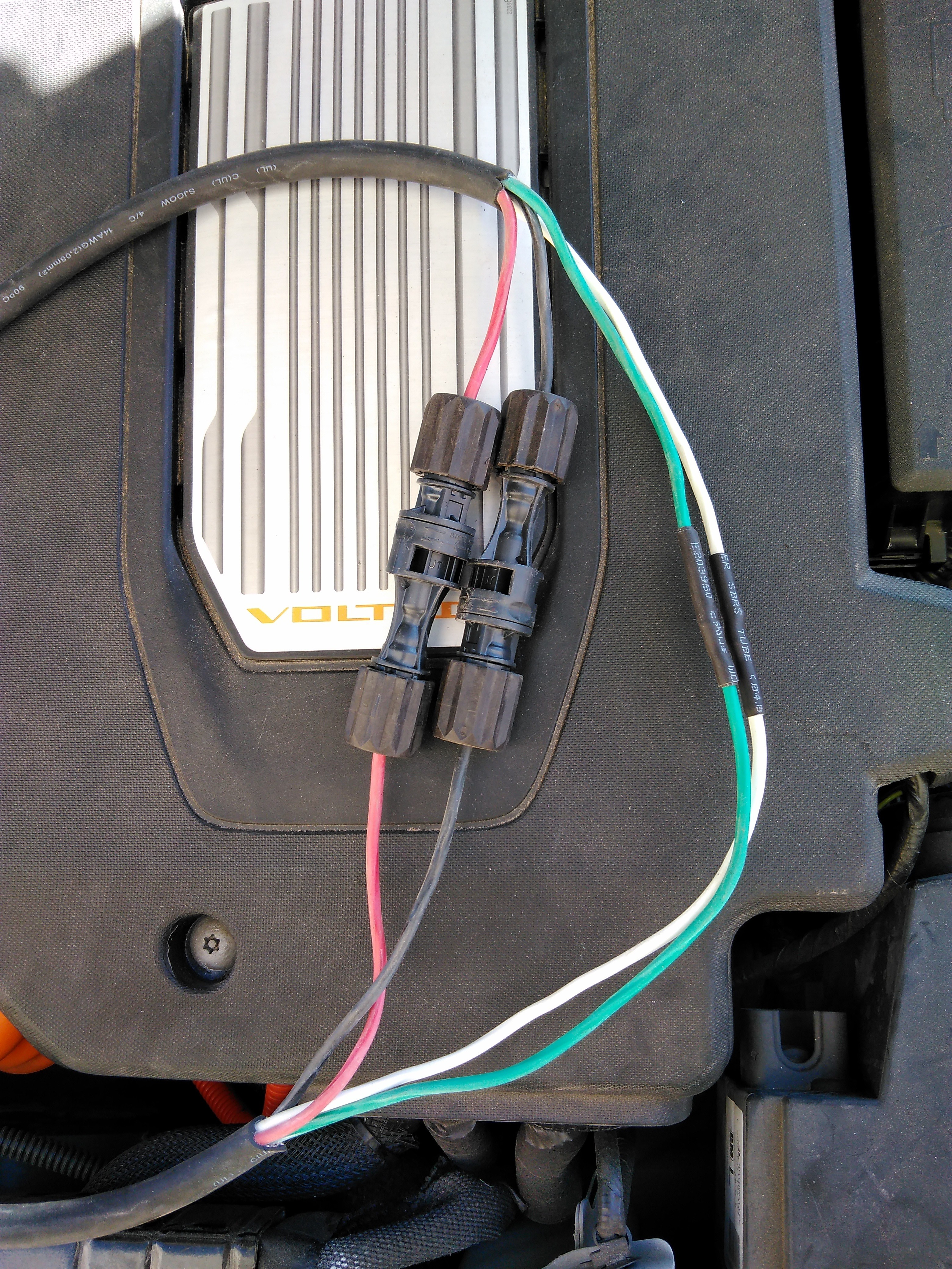
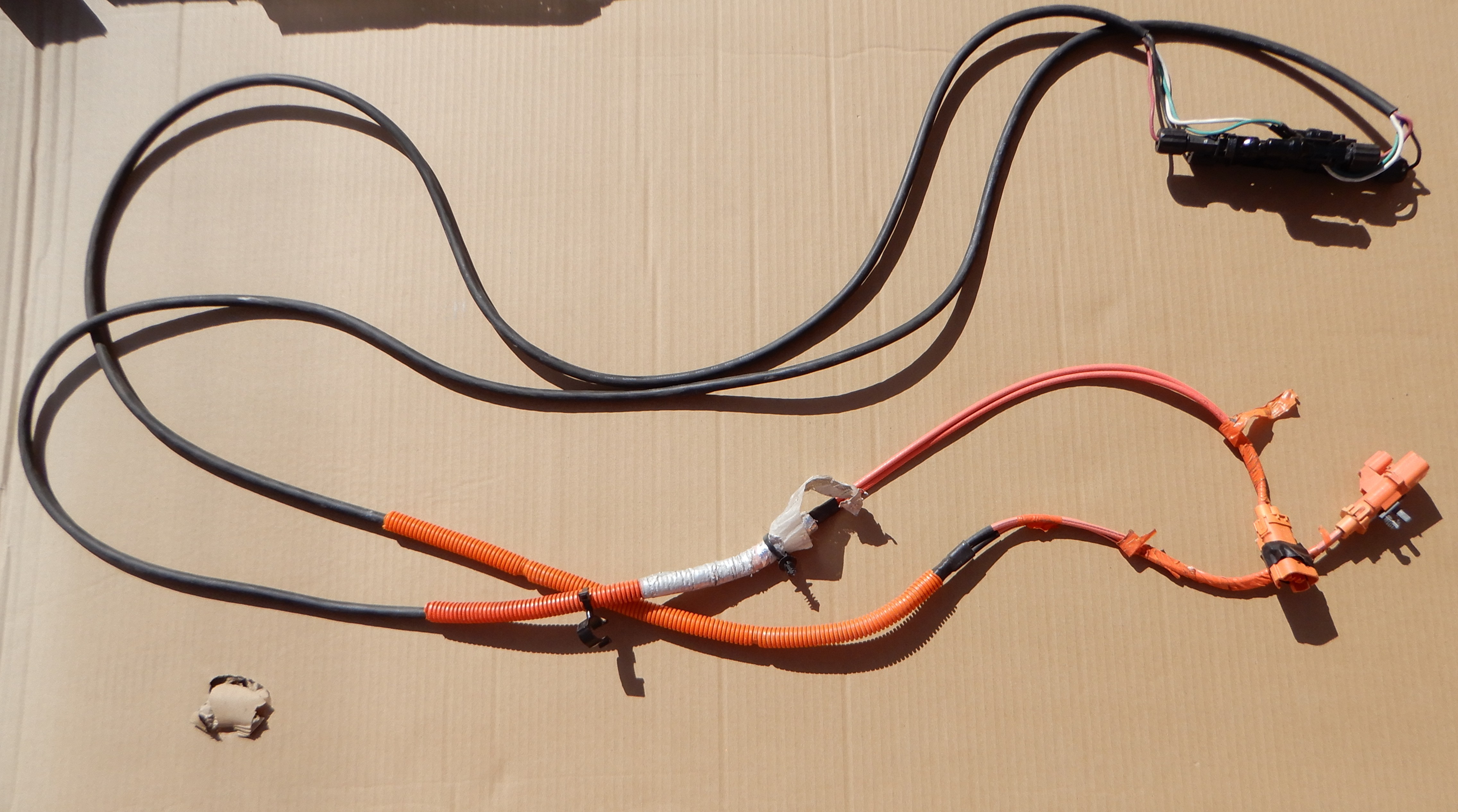
The completed HV cable assembly.
5
Installing the HV Interface Cable
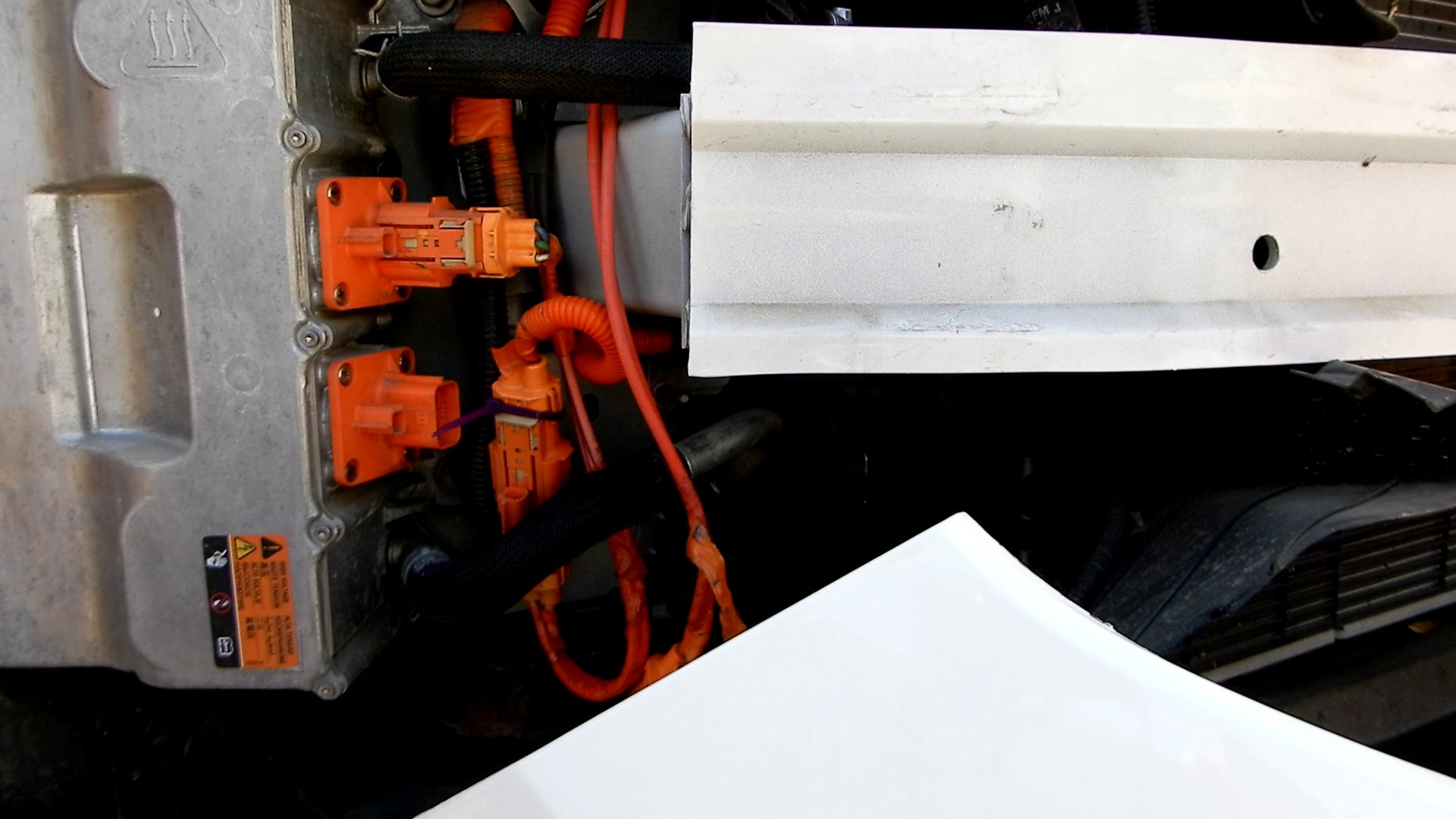
Unfortunately the HV cables you see upon opening the hood are connected to the main HV circuit. I wanted to connect to the charger HV circuit. Those connections are a lot more difficult to access.
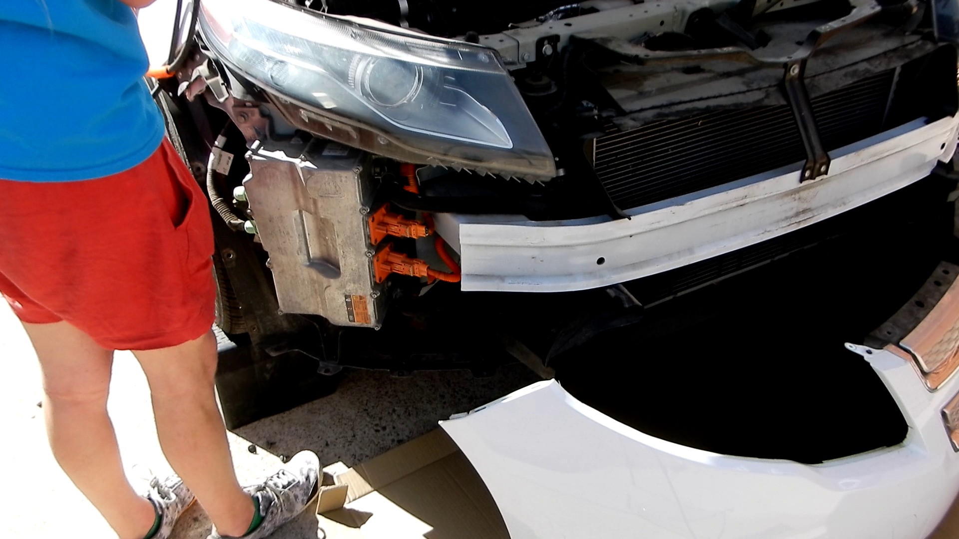
Remove the bumper according to the service instructions.
Route the HV Interface Cable down from the top. It might be necessary to loosen the headlight.
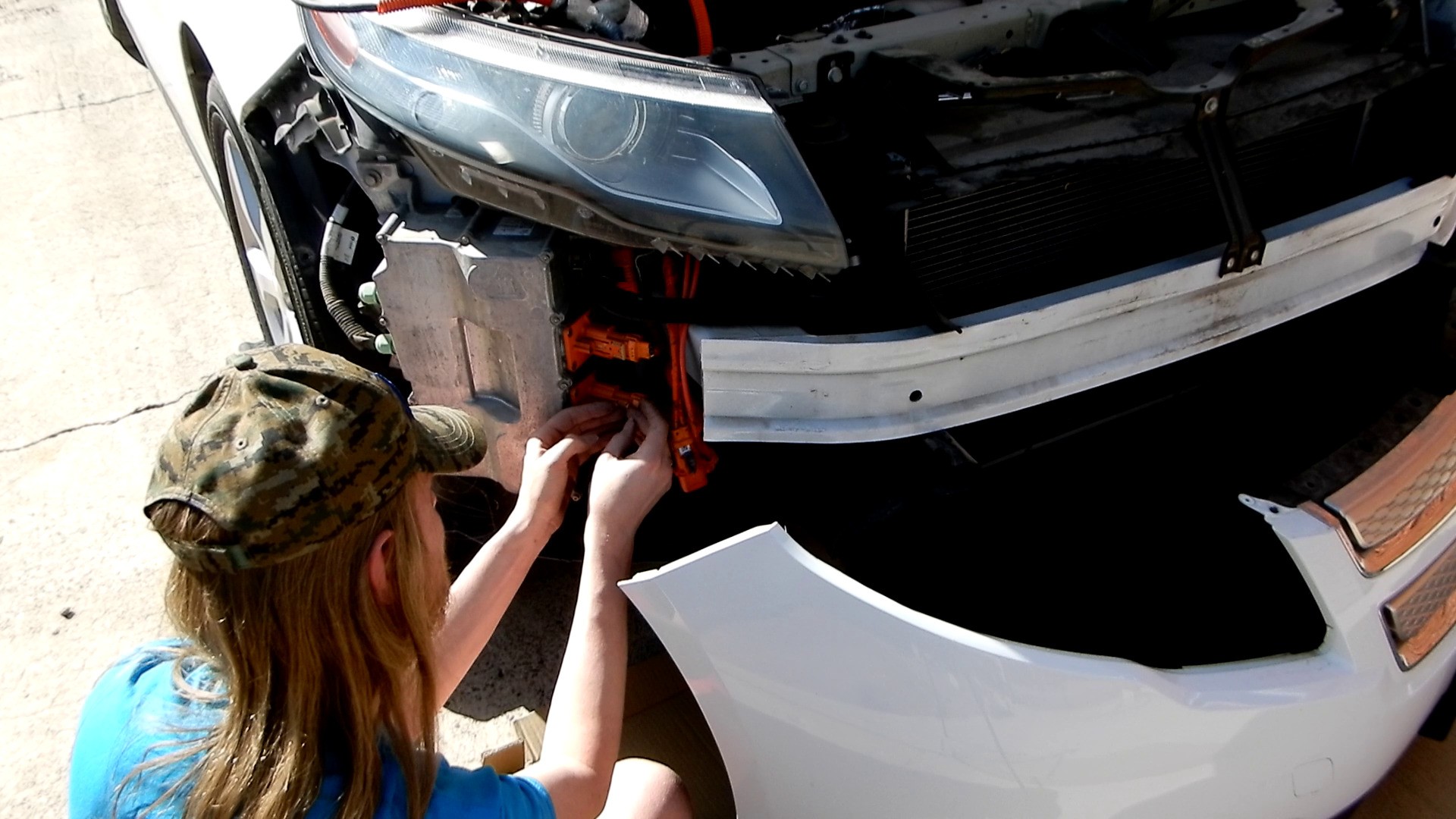
Disconnect the bottom HV connector from the battery charger.
Connect the factory HV cable to the HV Interface Cable. Secure with cable ties.
Connect the HV Interface cable to the battery charger. Seal with electrical tape since the connector had a slot cut into it.
Secure the HV Interface Cable with cable ties.
Reinstall the bumper. Tighten the headlight it you loosened it.
Route the rest of the HV Interface Cable to a safe place like on top of the HV motor cables.
6
Making room under the hood with an air intake reroute
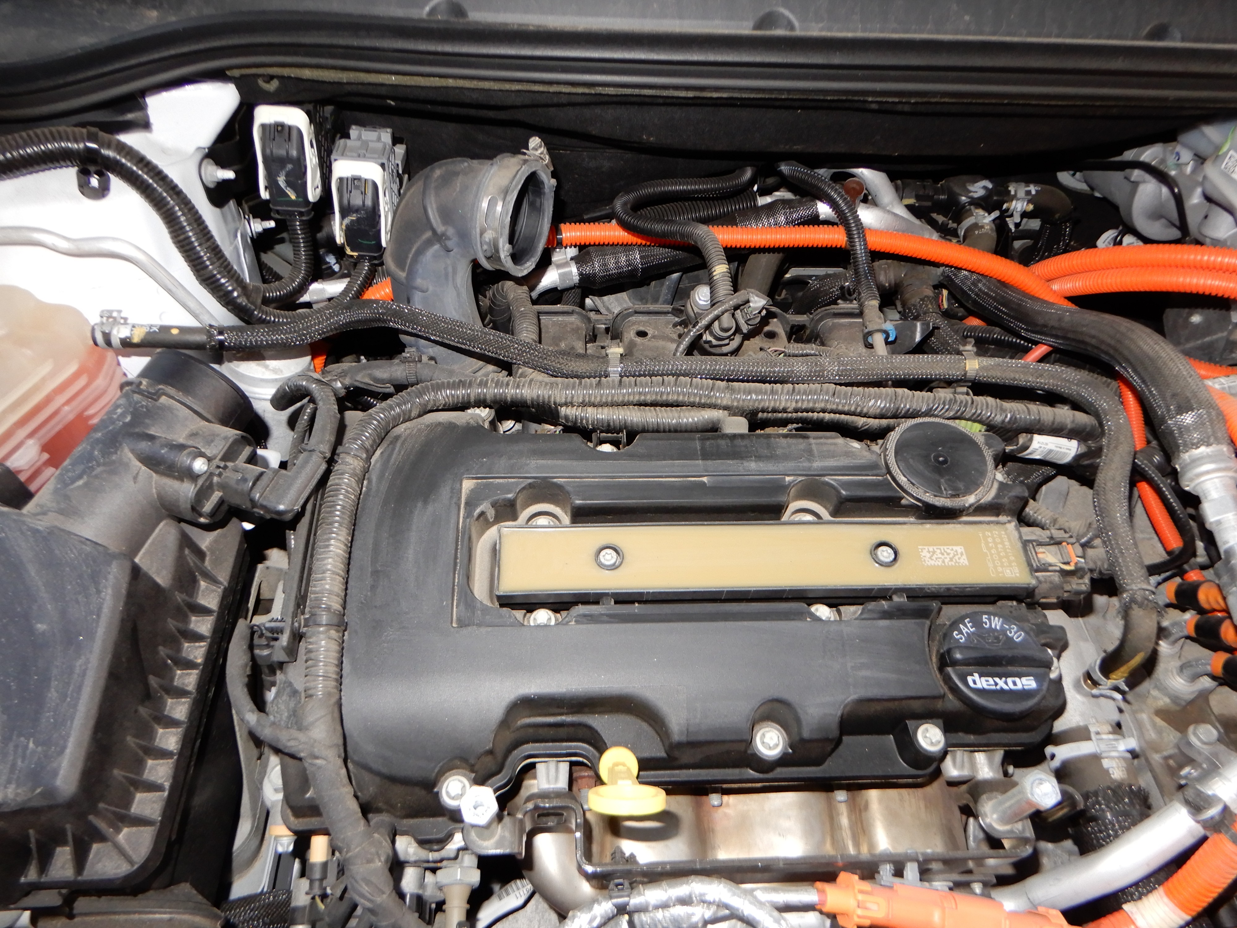
There is very little spare volume under the hood of a Chevy Volt. Fortunately we can remove the engine cover to create a large open area with several inches of available height. The air intake is routed through the engine cover, so the air intake must be modified.
Remove the engine cover.
Loosen the hose clamp at the base of the periscope shaped hose.
Rotate the hose so the opening faces the air filter box.
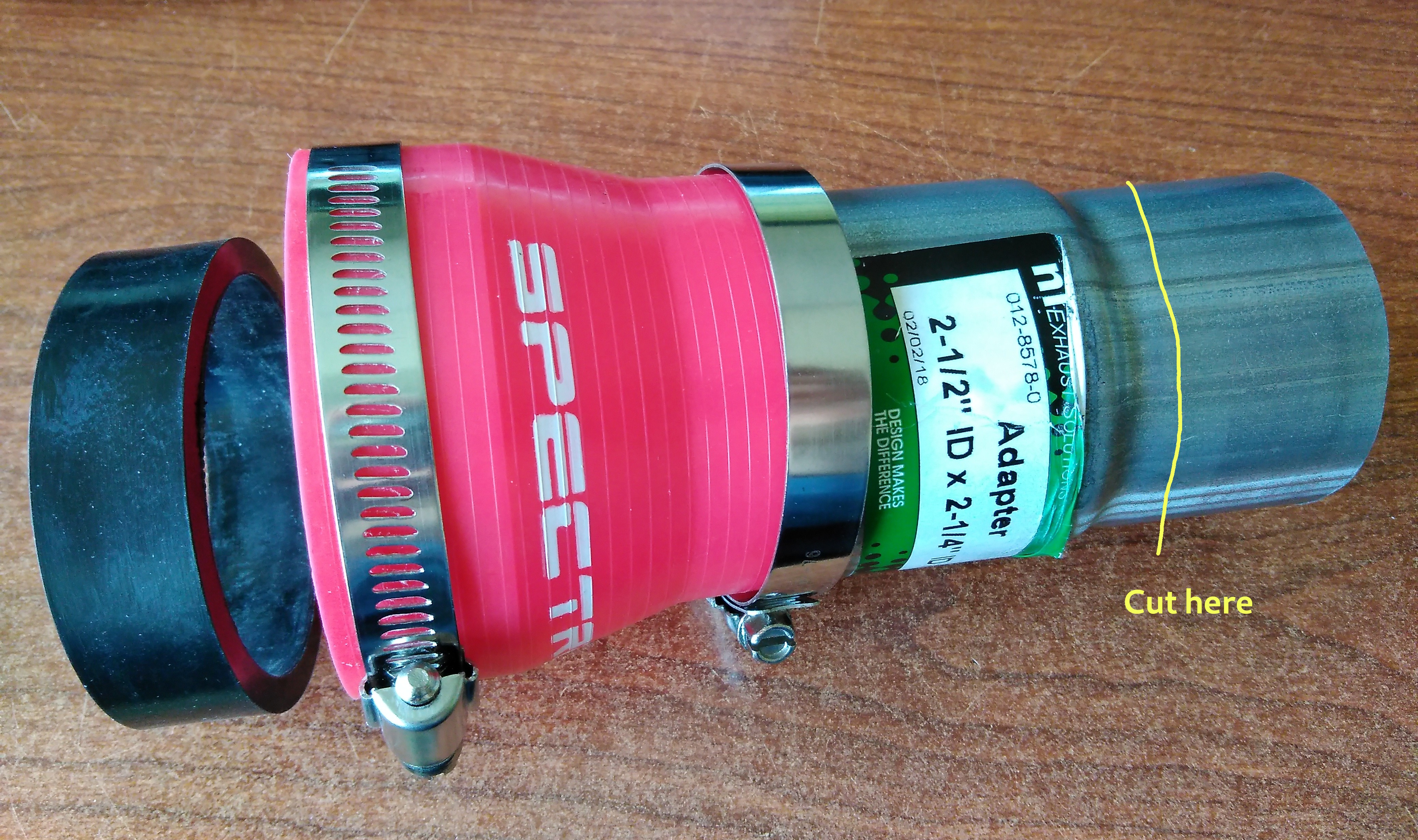
Cut the exhaust fitting, leaving about 1/2" of the small diameter section. File the end smooth. Be sure all metal filings are removed.
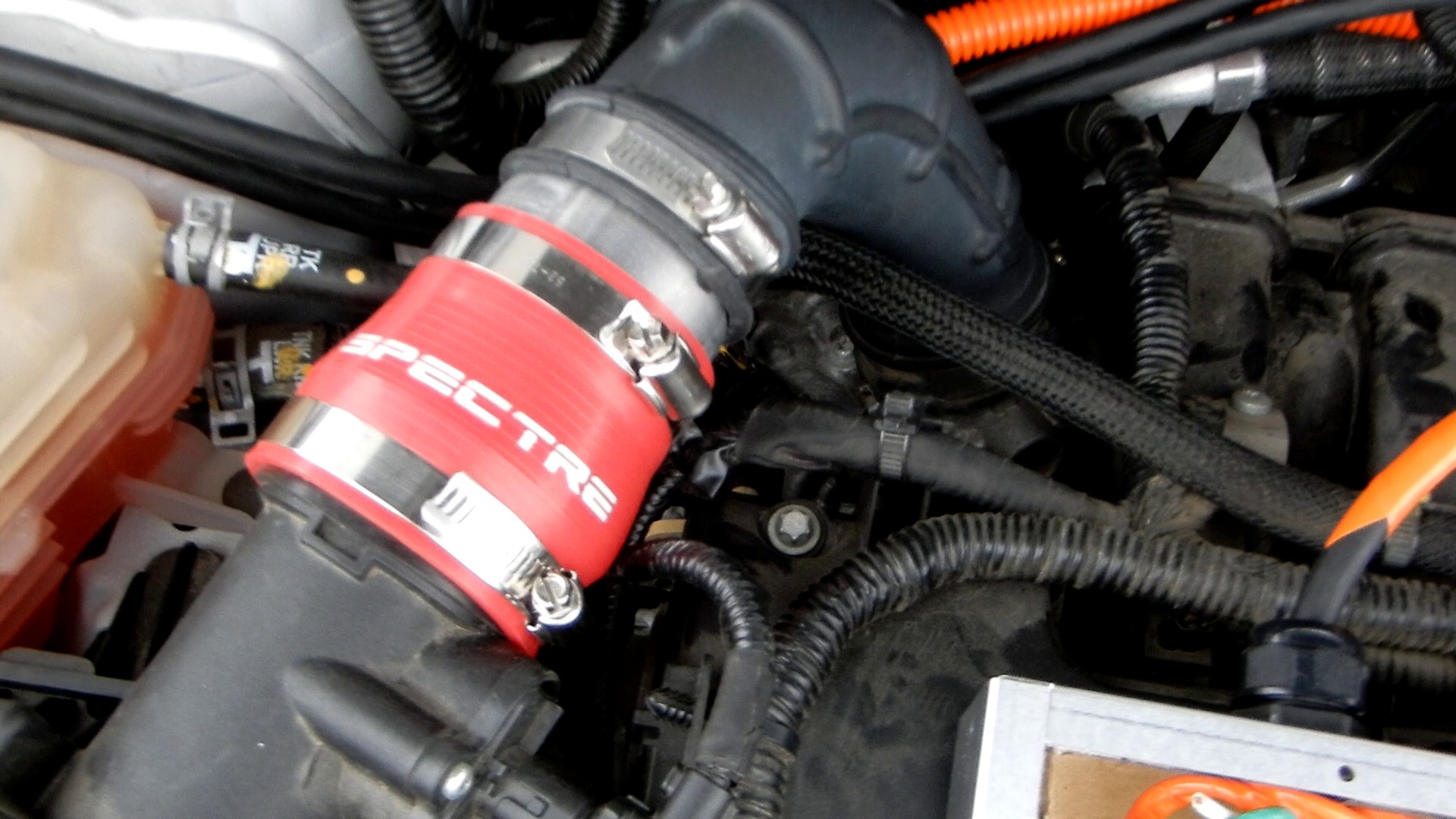
Assemble the pieces as shown. The black ring came with a 3" to 3" coupling that I didn't use.
Tighten all hose clamps. Don't forget the one at the base of the periscope hose on the throttle body. I recommend a ratcheting wrench to reach that one.
7
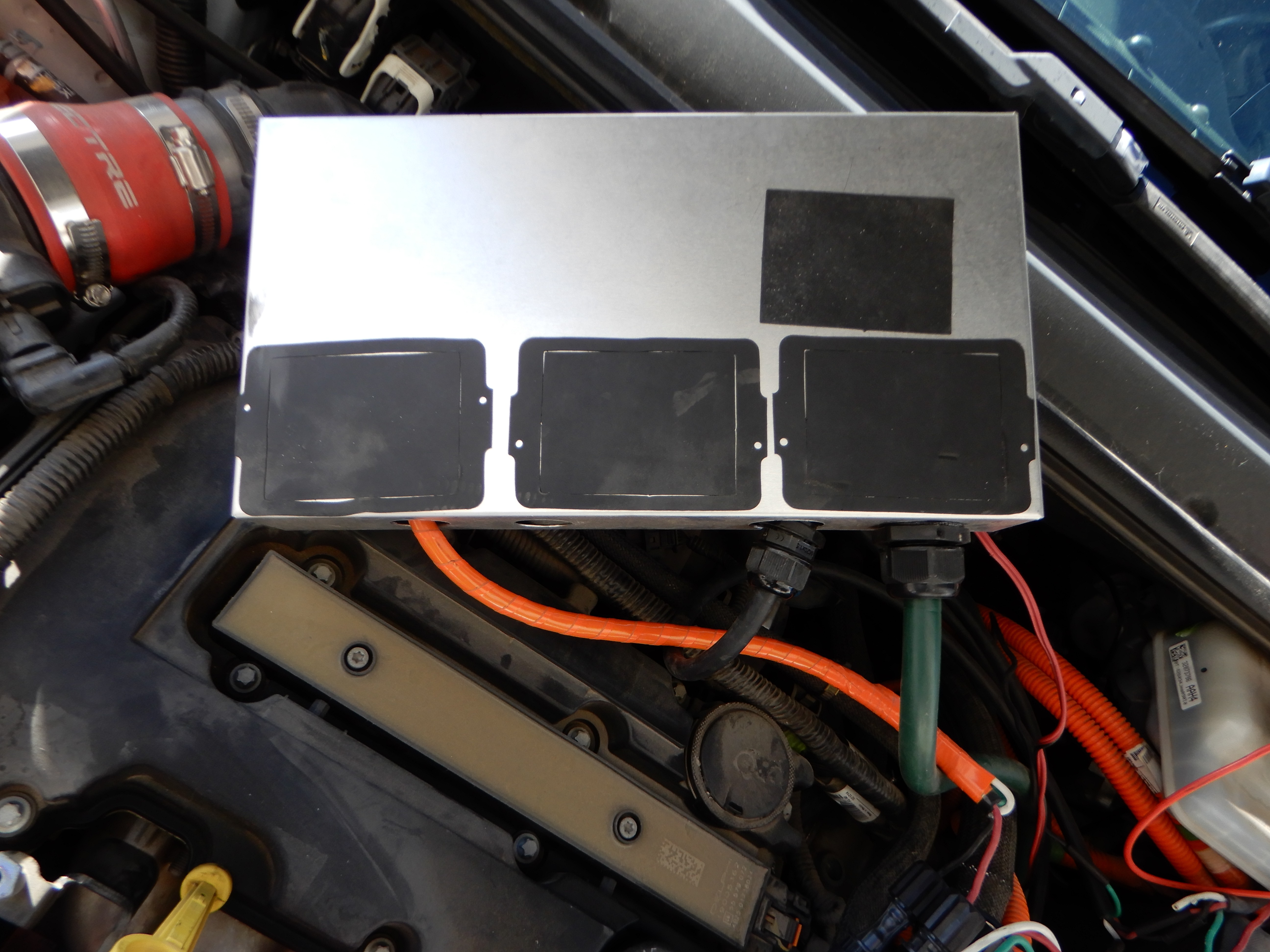
Installing the Charger Box
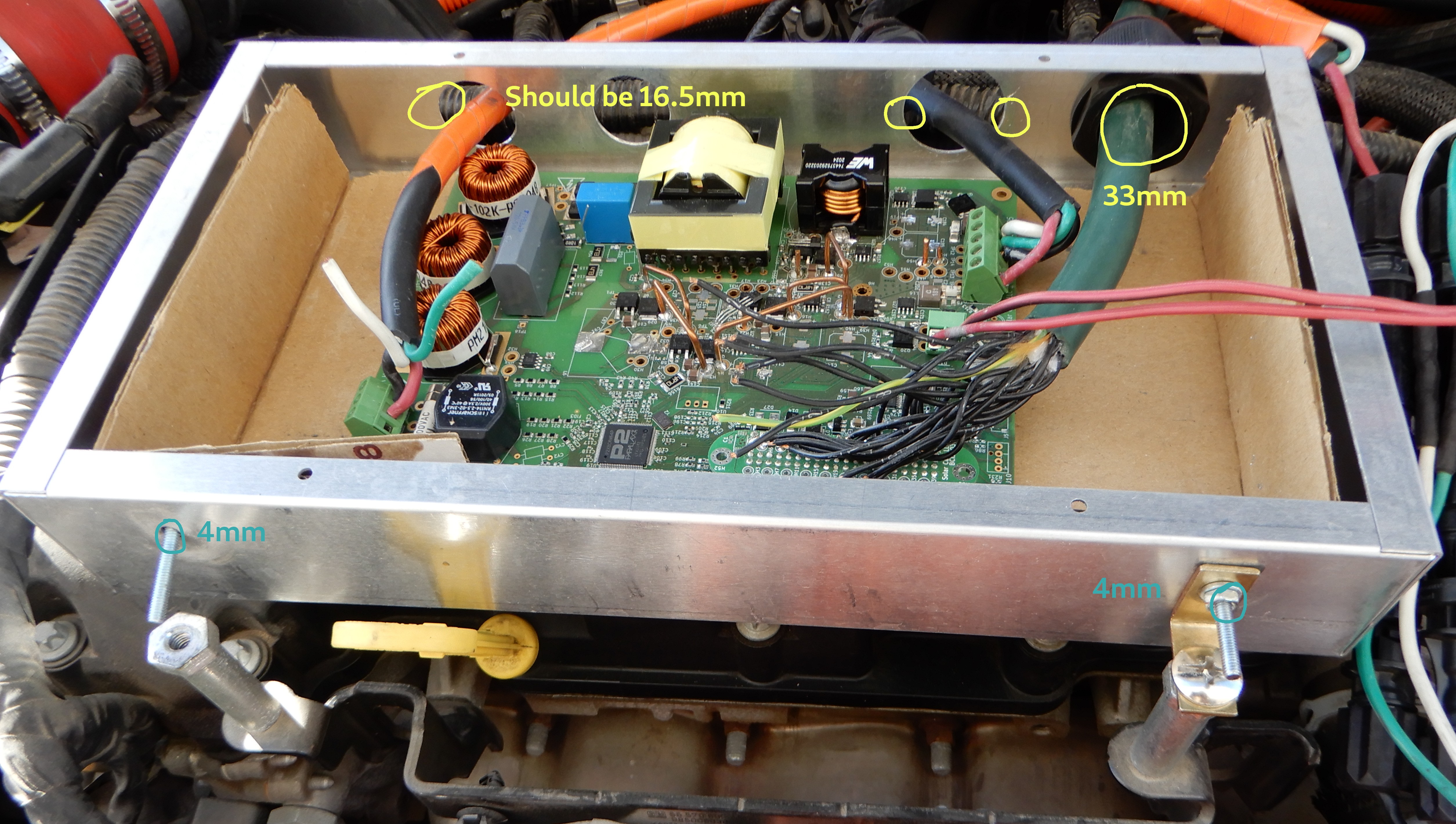
I'm still using the same box that I used with the PCDB1910. The newer PCDB2105 is a smaller and should go into a more water resistant Bud EXN-23366 enclosure. The enclosure shown is 2x7x13".
Drill holes in the side of the box for mounting bolts and cable glands. The box shown has larger holes from when it was used previously. I suggest 3 holes for the small cable glands and 1 hole for the large cable gland.
Apply adhesive rubber sheet to the bottom of the enclosure.
Bolt an angle bracket between the enclosure and the studs used to mount the engine cover.
Cut a piece of plastic or cardboard to insulate the PCB from the aluminum box. The older PCDB1910 did not have mounting holes. The newer PCDB2105 does, but I'll be replacing this box with an extruded aluminum one soon.
8
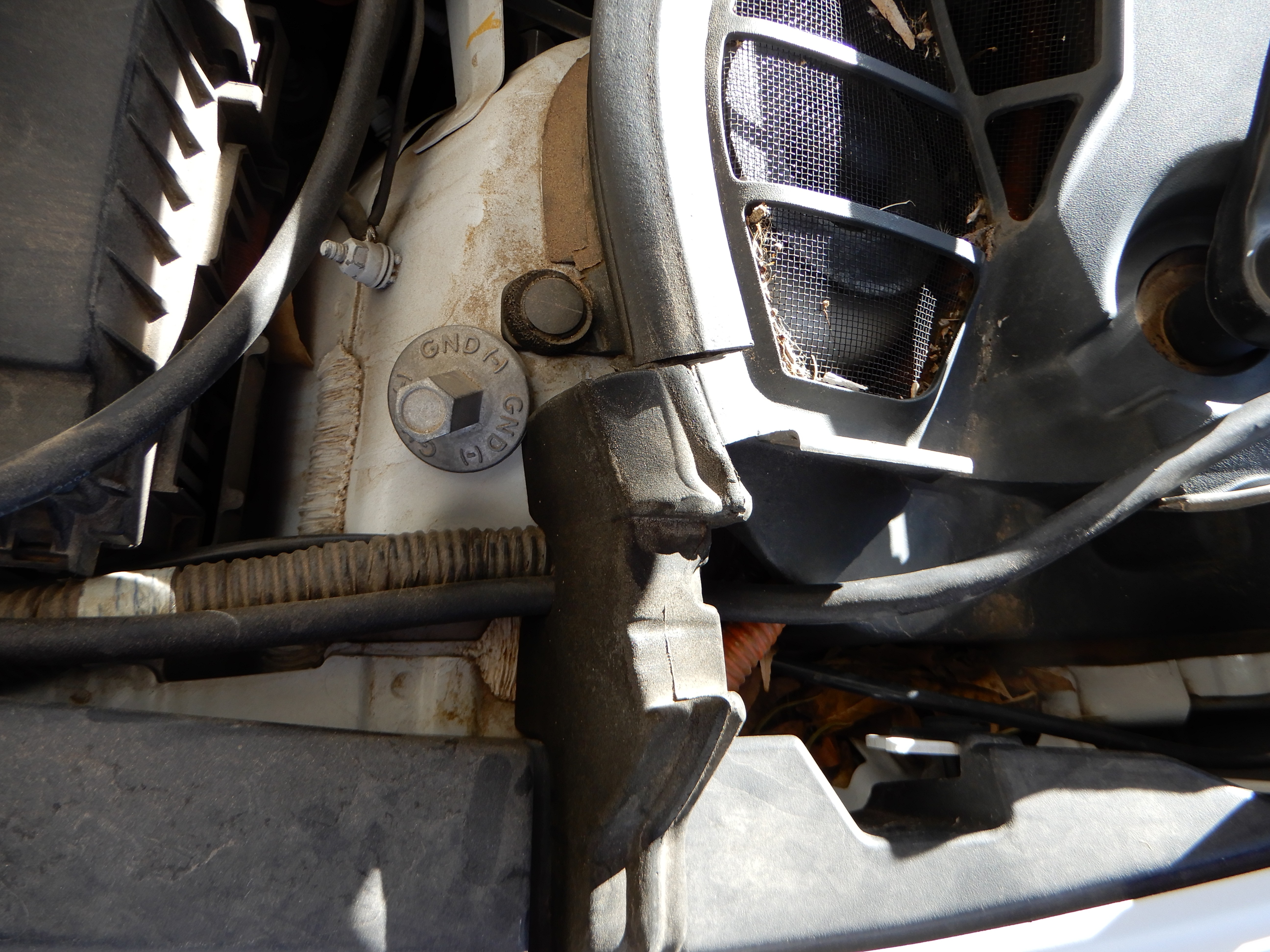
Step 8
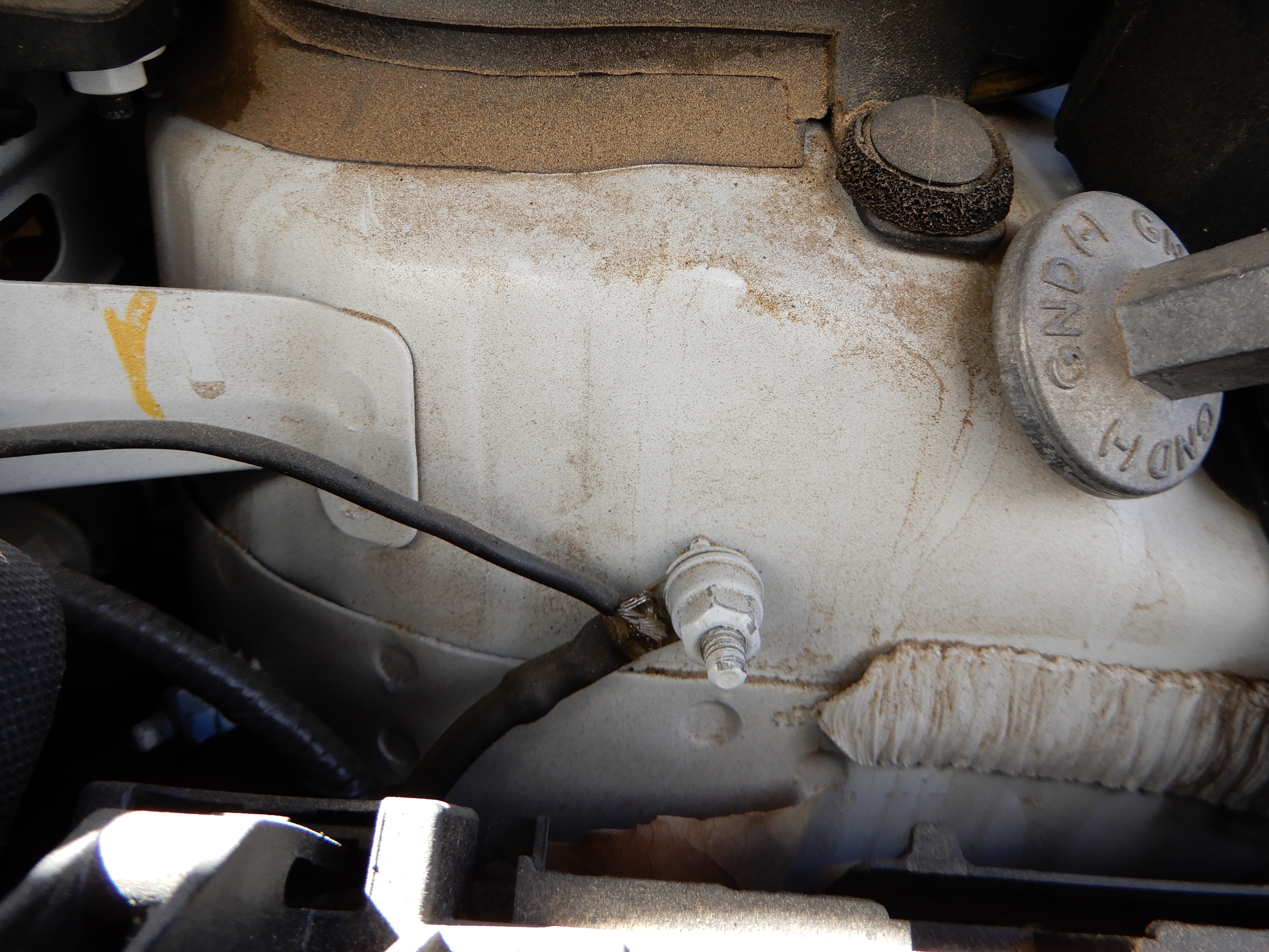
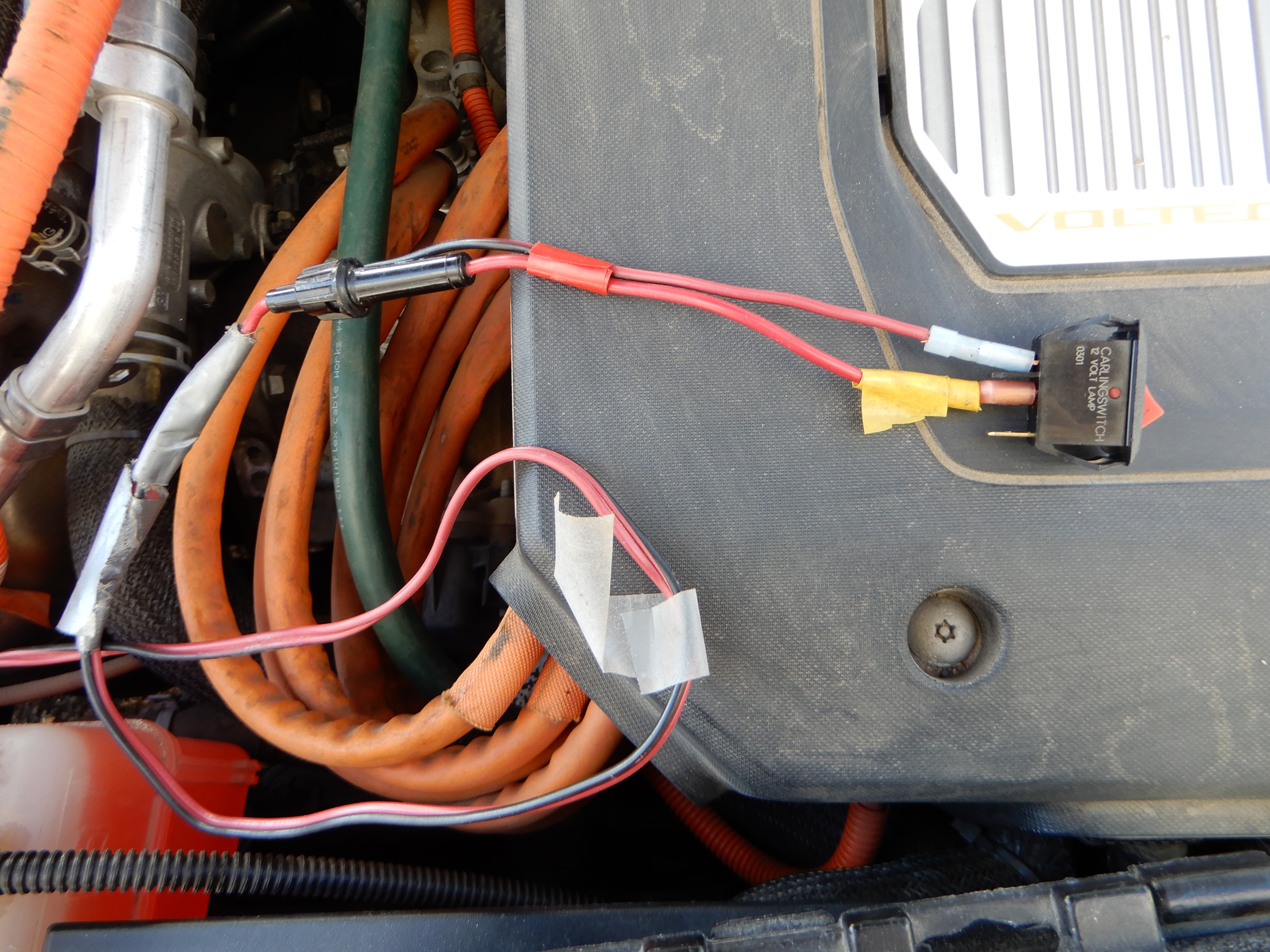
The PCDB2105 needs a ground connection since the Battery Interface Cable does not connect to any ground wires. I chose to solder a wire to this factory ground terminal.
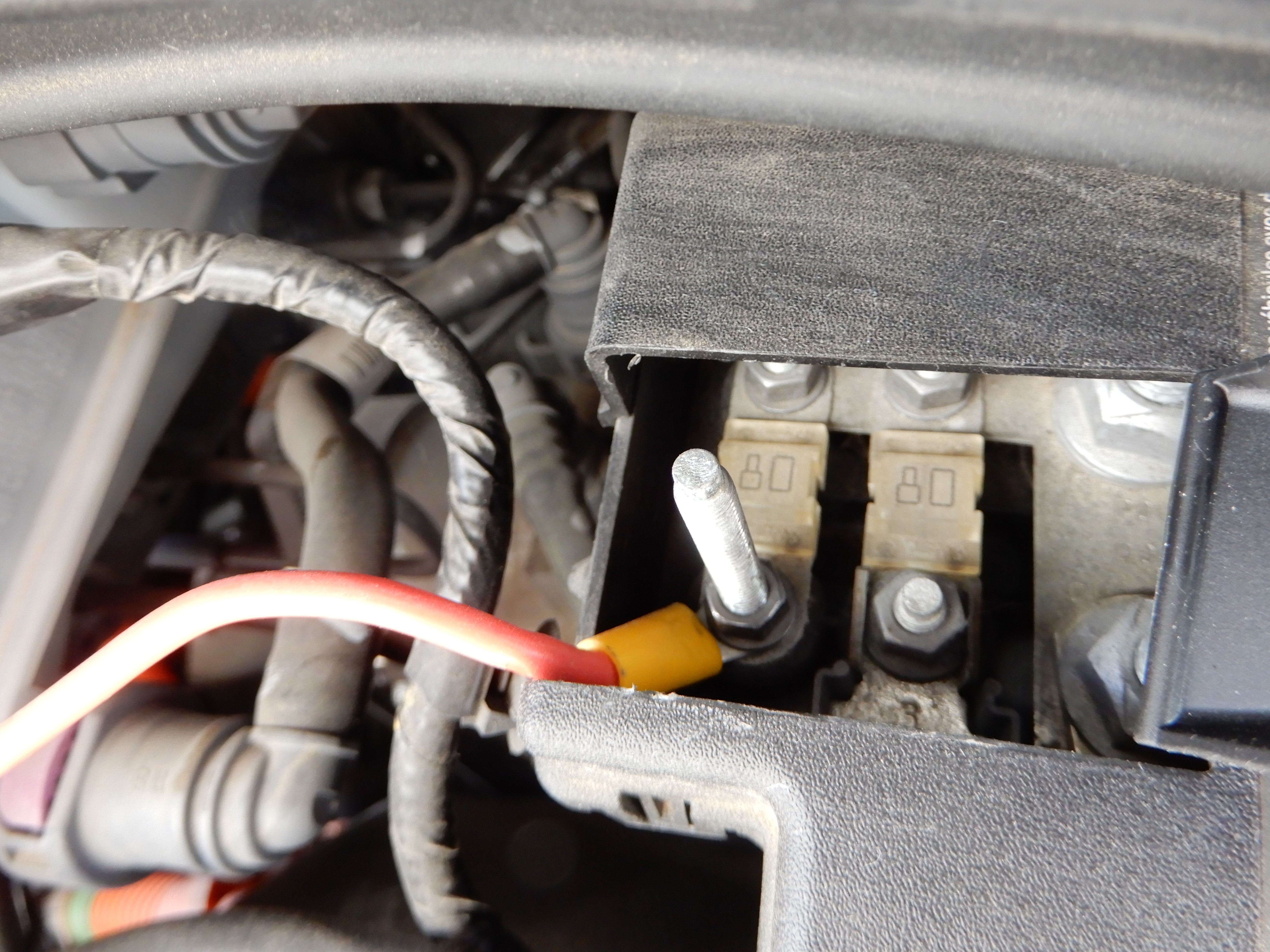
The charging post was a convenient place to connect to 12v power using a ring terminal.
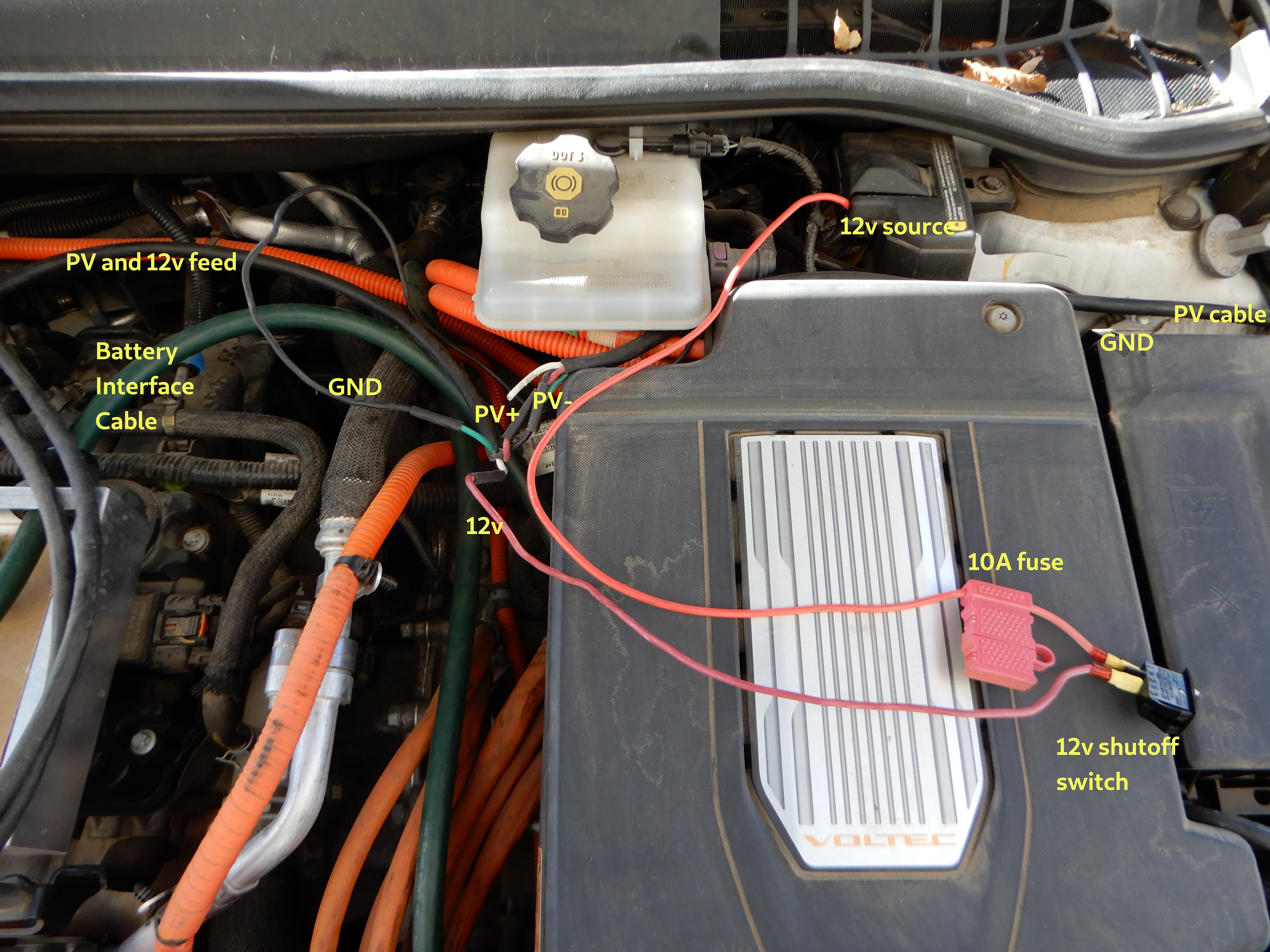
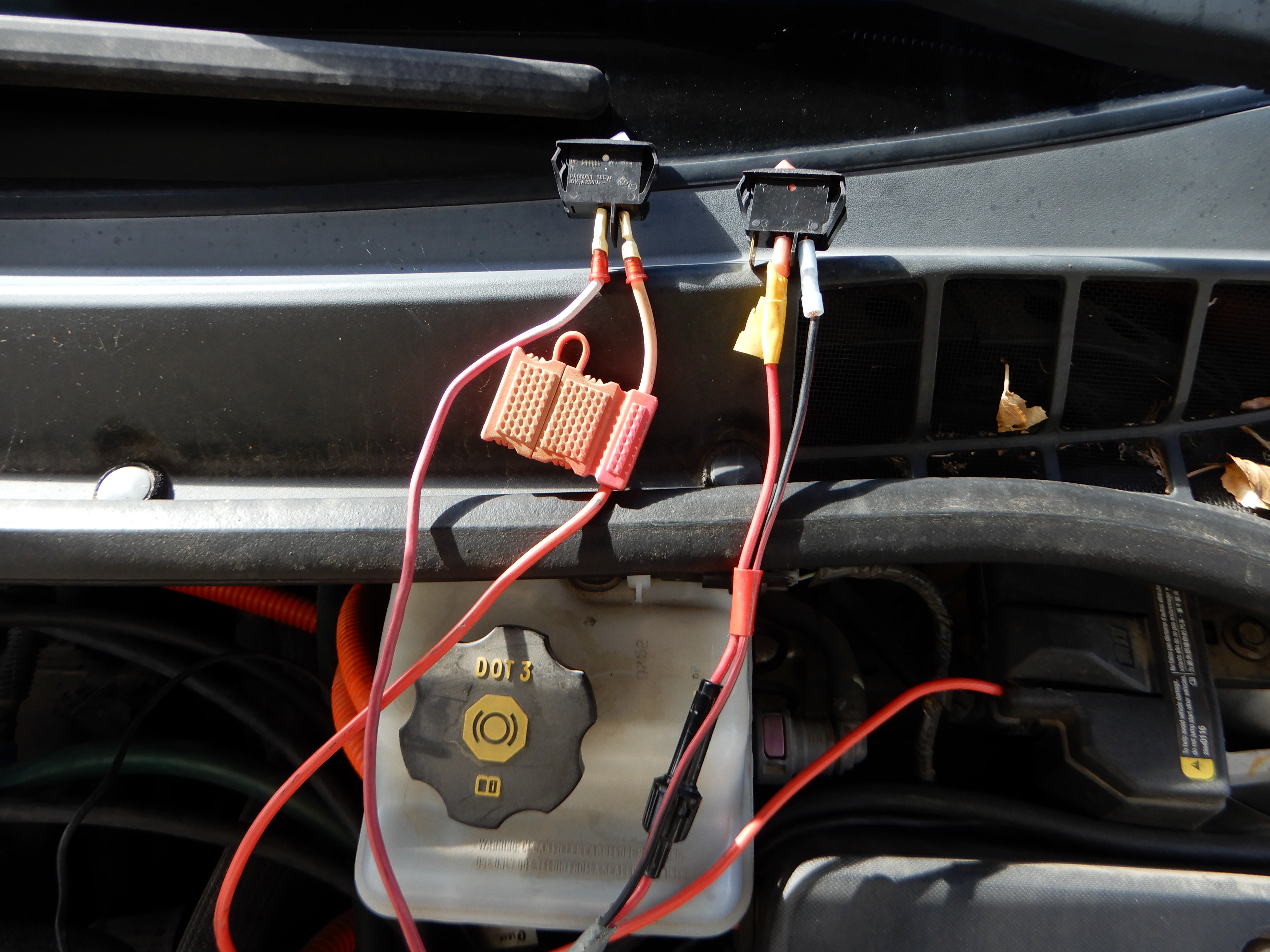
The 12v power is protected by a 10 amp fuse, then it runs through a rocker switch to allow the board to be shut down. The PV supply and 12v supply are spliced into a short piece of 14/4 SJOOW cable to reduce the number of cables running into the charger box.
Since the PCDB2105 outputs 12v as well as high voltage, it needs an additional shutdown switch to ensure it does not keep feeding itself 12v power derived from the PV input. A fuse is not needed on this line since it is protected by the other 12v fuse.
The logic shutdown switch is connected in place of D44.
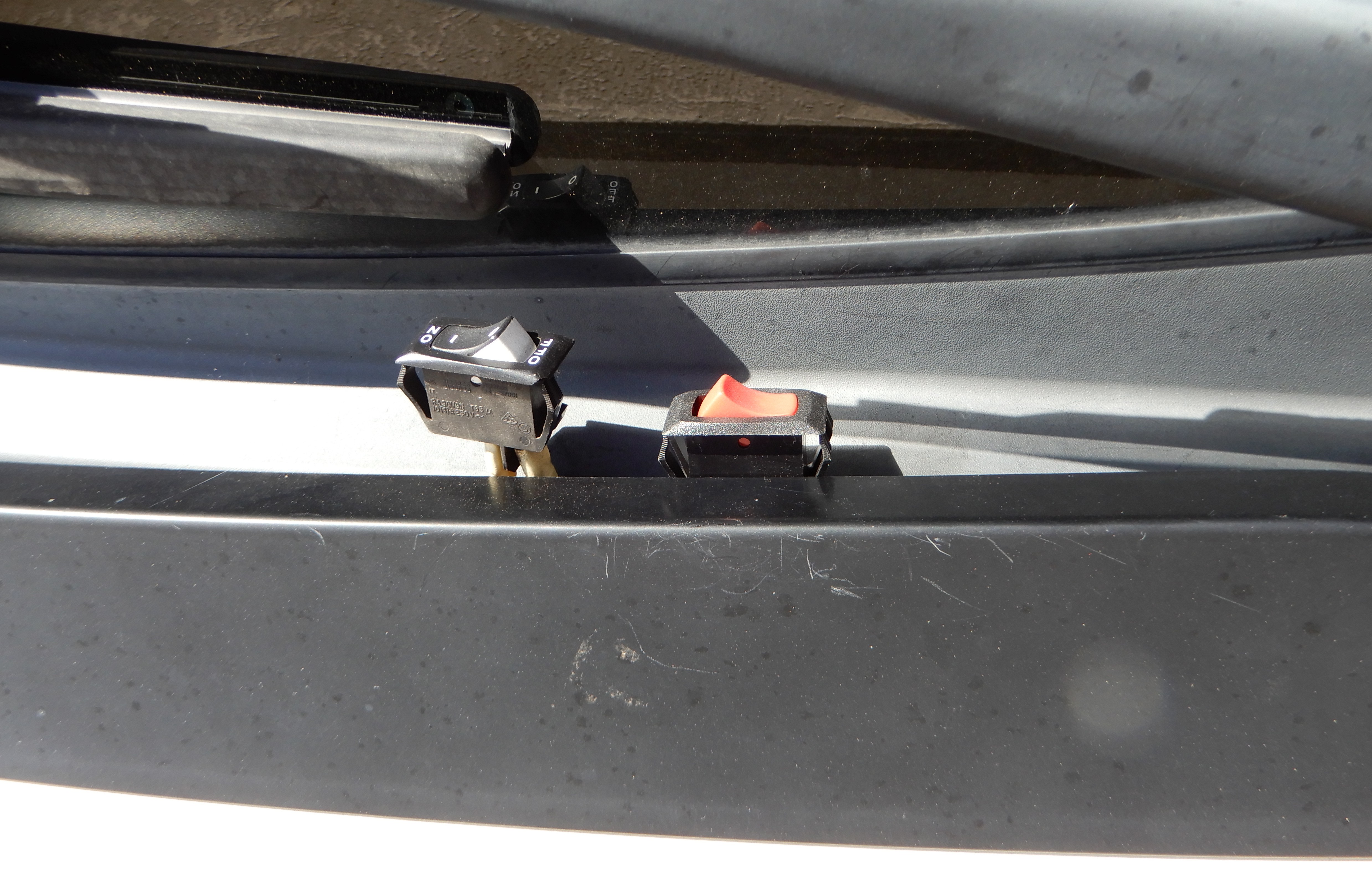
The rocker switches are positioned so they can be operated with the hood closed.
Carefully close the hood.
9
Build a data logger
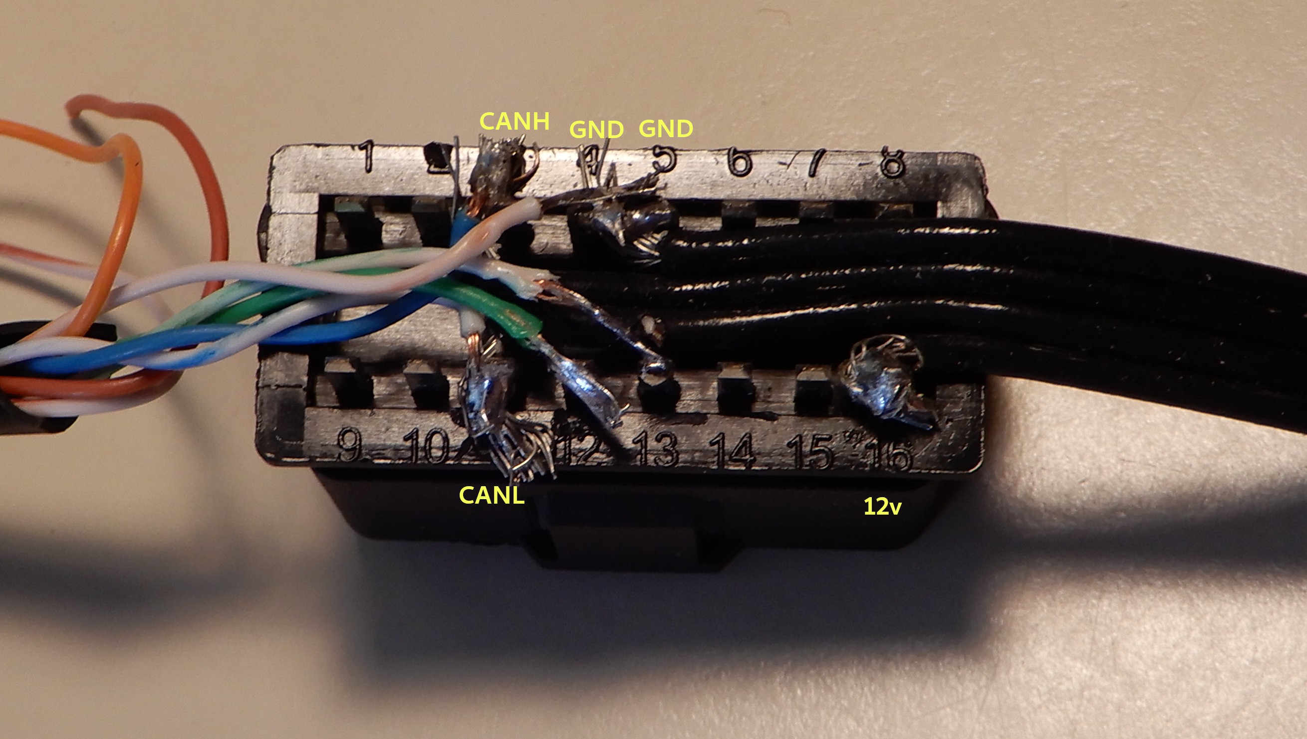
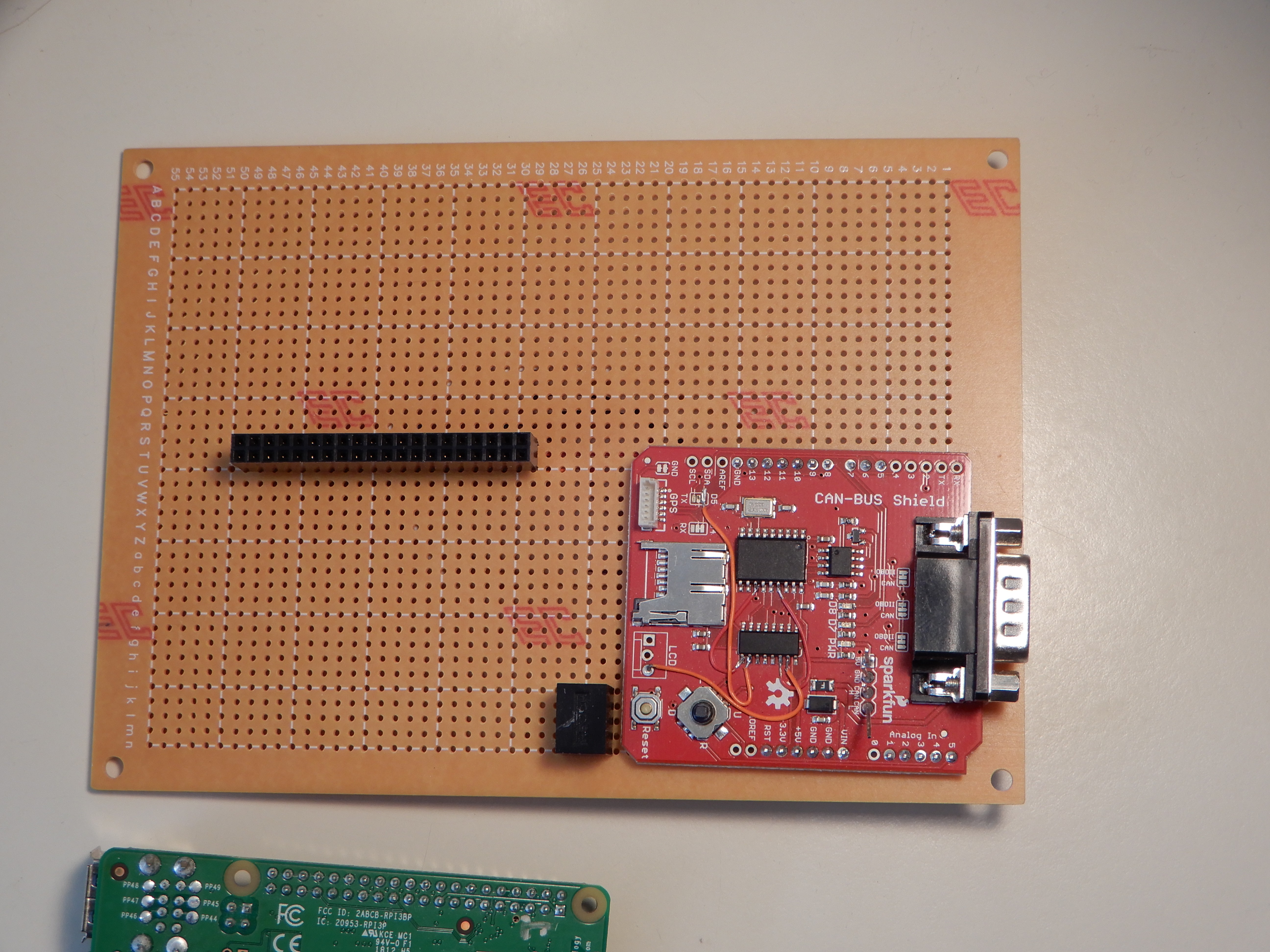
There are CAN bus interfaces made for the Raspberry Pi that will make this section easier. I don't recommend modifying the CAN-BUS shield like this. But it works so I don't fix it.
The datalogger needs to connect to the high voltage management CAN bus. This is the second CAN bus on the second OBD port (on the passenger side.) So I had to build my own CAN interface cable.
I added jumper wires to repurpose the SD card level shifter to shift the outputs from the MCP2515. Look for 2 orange wires and 2 red wires. The level shifter outputs go to unused pins.
The MCP2515 signals are connected to the SPI interface on the Raspberry Pi. A 3 terminal switching regulator provides 5v power to the Raspberry Pi 3 B+.
Program a microSD card with Raspberry Pi OS.
Configure your WiFi network(s).
Enable SSH and/or VNC for headless operation in the car.
tar xvf datalogger.tar in the pi home folder.
Install config.txt in /boot and rc.local in /etc
Shutdown.
Connect to the Passenger Side OBD port with the custom cable.
10
Building the PCDB2105
Most of the parts can be populated according the Interactive HTML BOM.
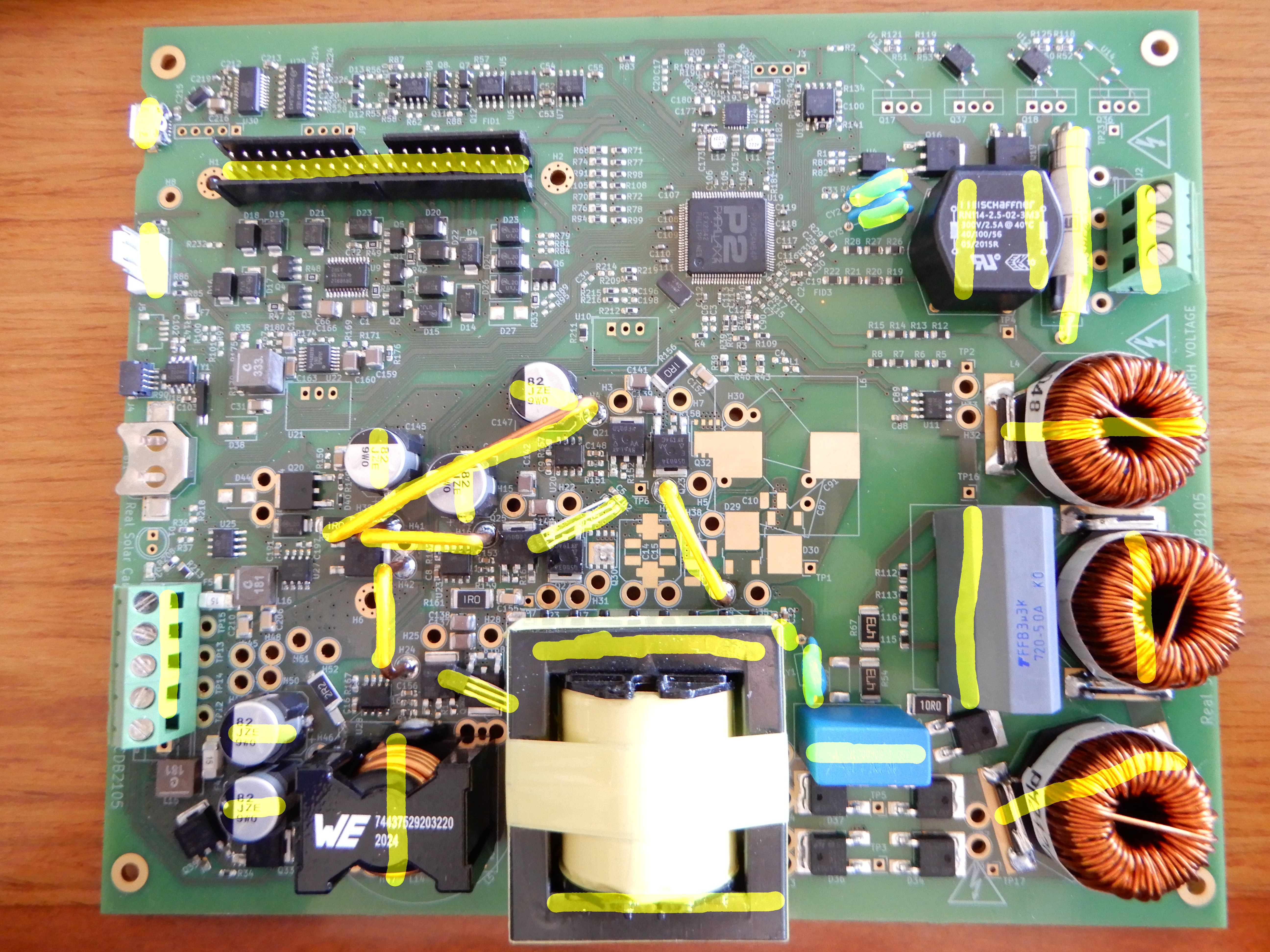
Parts marked "postasm" should not be populated until later. They are bulky or water sensitive. Those parts are marked in yellow.
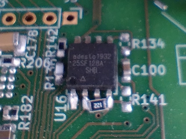
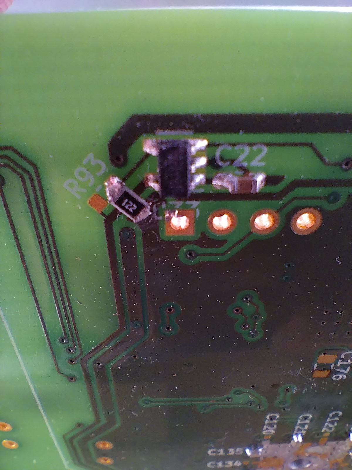
The SPI flash used needs a pull-down resistor. 1.2k works.
A resistor for the internal power switch needs to be connected to ground instead of 3.3v. Scratch away some soldermask to make the ground connection.
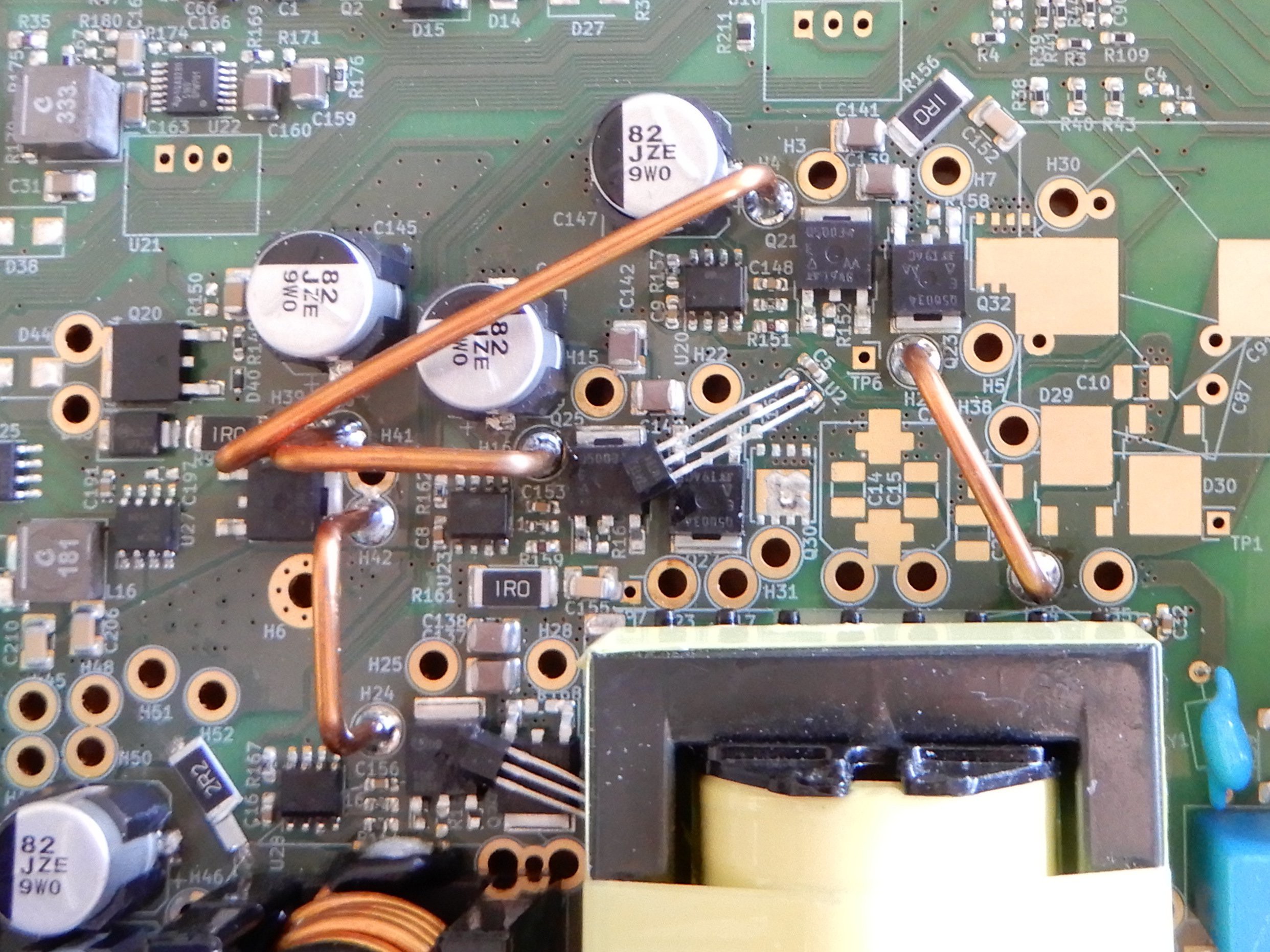
The TO-92 temperature sensors need to be mounted specially to measure the temperature of the mosfets (or the transformer.) The board needs 4 jumper wires made from 14 or 12 AWG solid copper wire to supply high current to the mosfets.
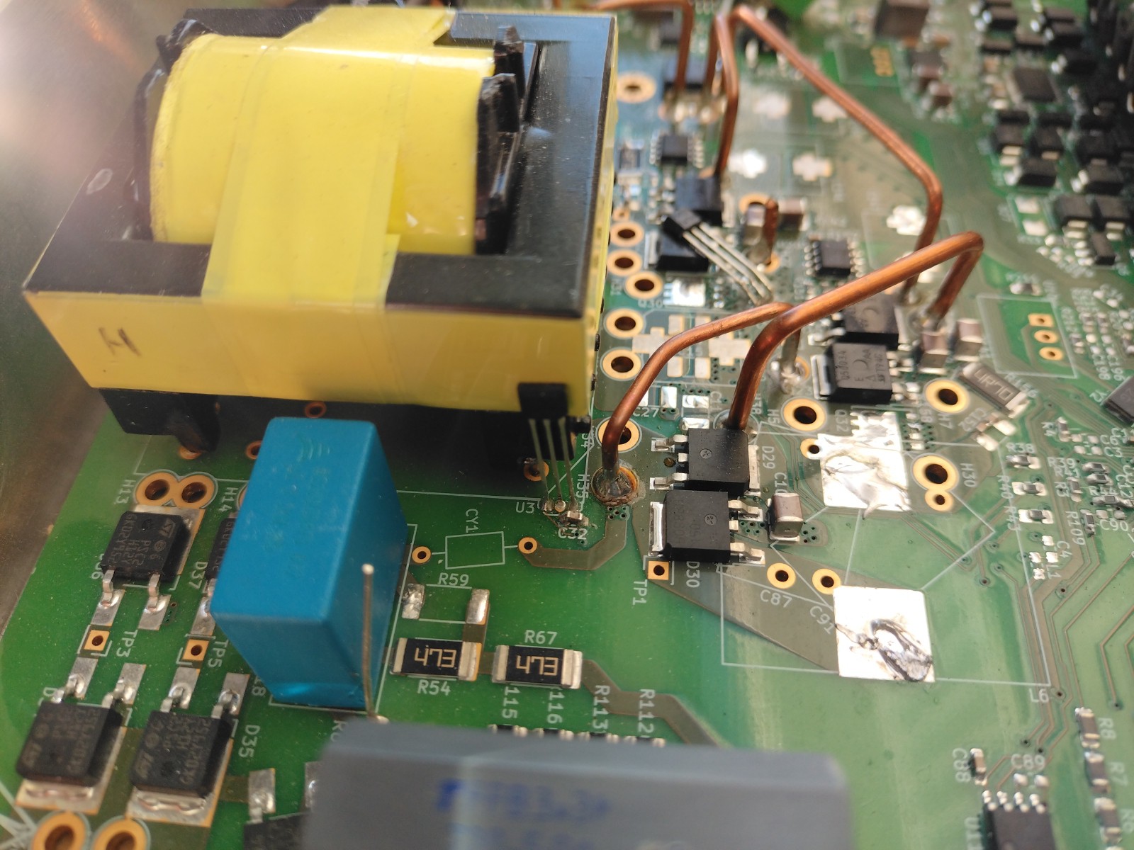
The "postasm" parts can be mounted now. I suggest going from shortest to tallest. The transformer does not have polarity markings. Look for multiple thick wires on the primary side and thin wires on the secondary side. The secondary side goes towards the outside edge of the board.
The transformer temperature sensor is mounted after the transformer is installed. If desired, they may be attached to the measured components with superglue.
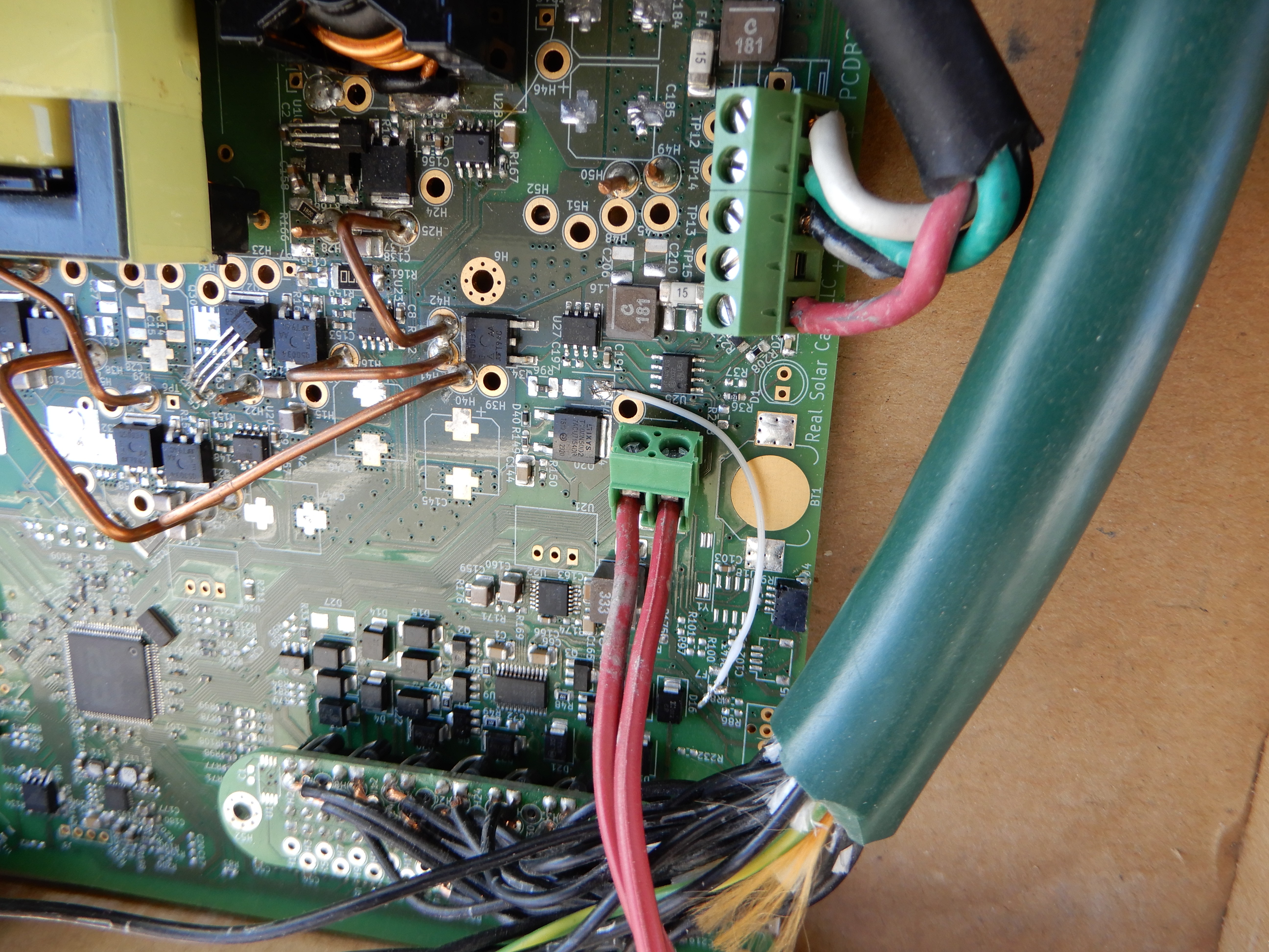
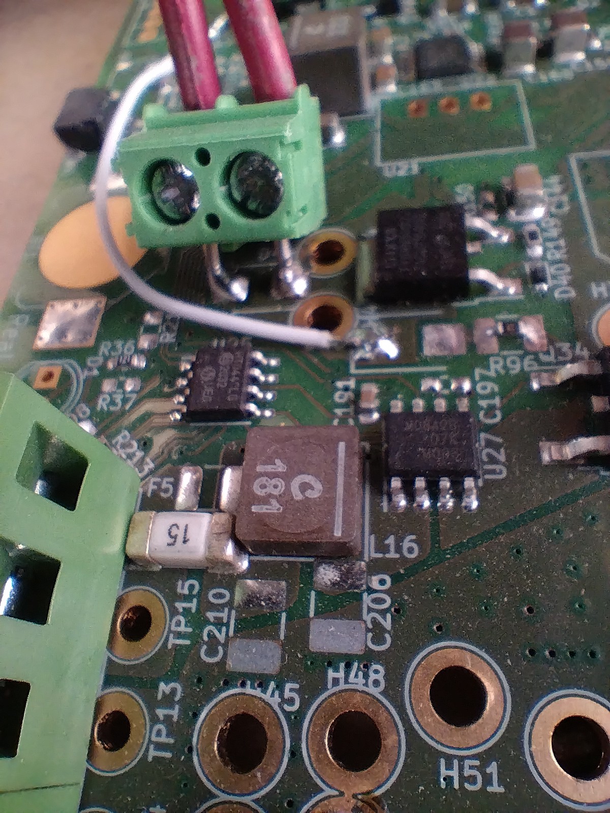
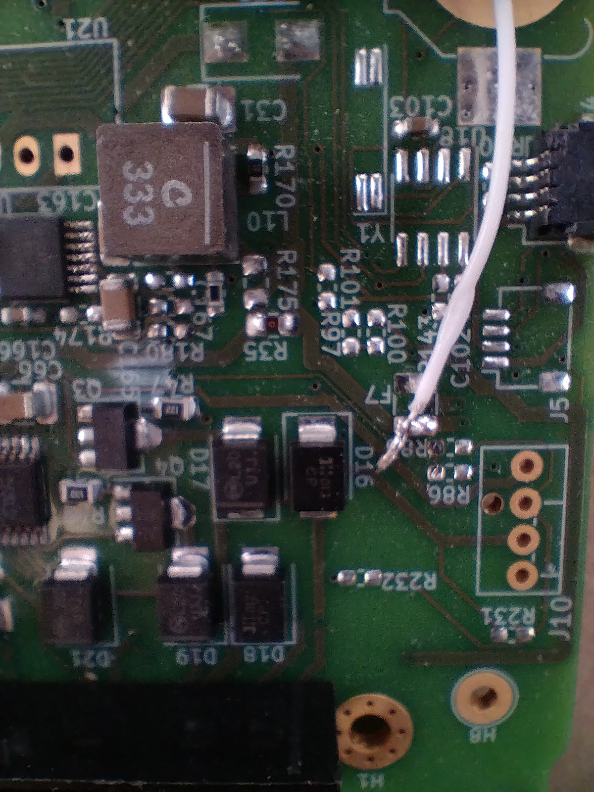
D45 is not populated. This part allows the PV input to supply the board's internal needs. This is undesirable since it will feed 40v from the panels to the DRV8912 relay driver. A 2 pin terminal block is connected in place of D44. This allows the use of the external logic power switch. A jumper from the cathode of D45 to F7 powers the relay driver from the VSYSTEM bus.
 Real Solar Cars
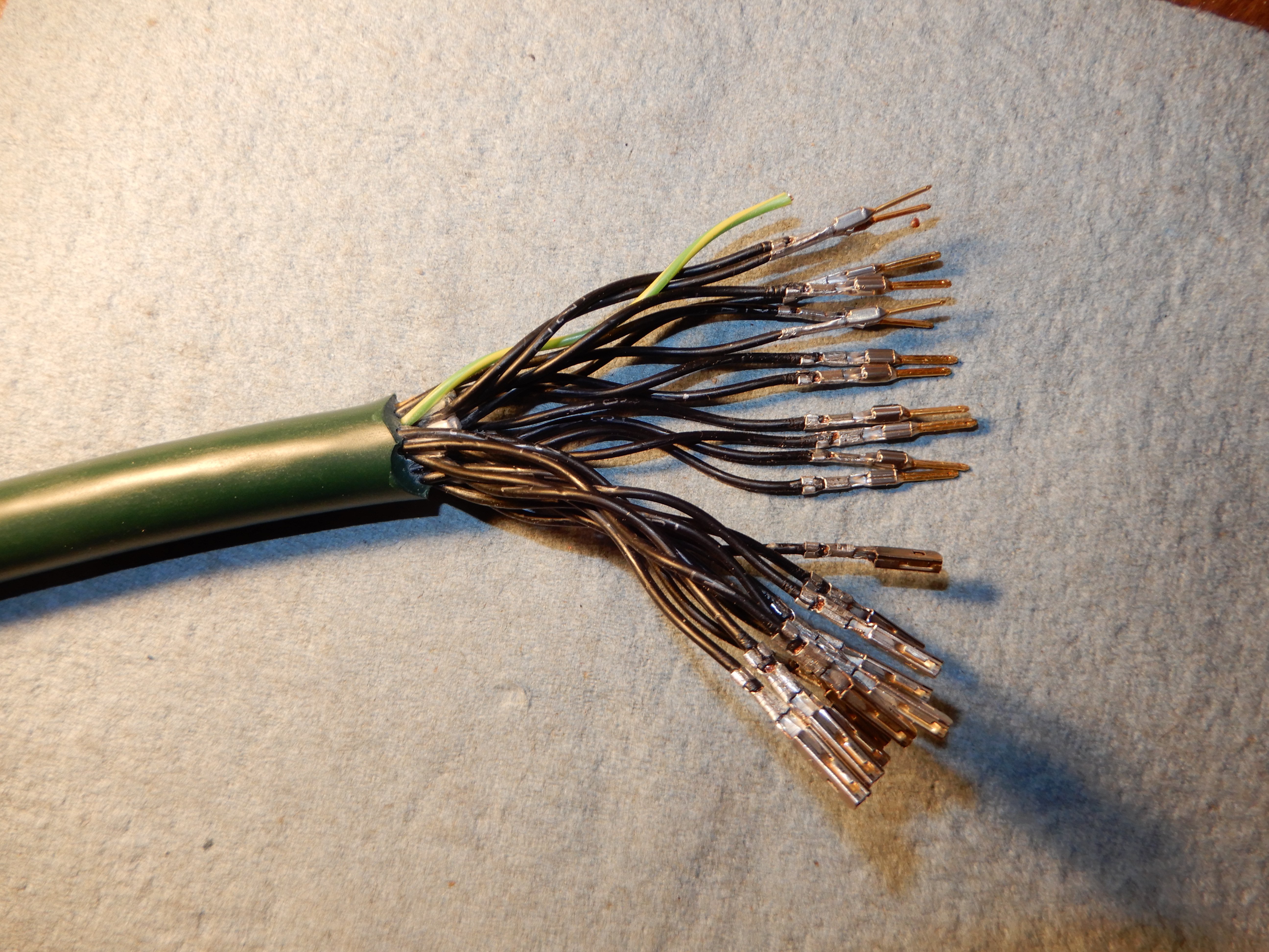


Discussions
Become a Hackaday.io Member
Create an account to leave a comment. Already have an account? Log In.