-
1Preparing the capacitor bank
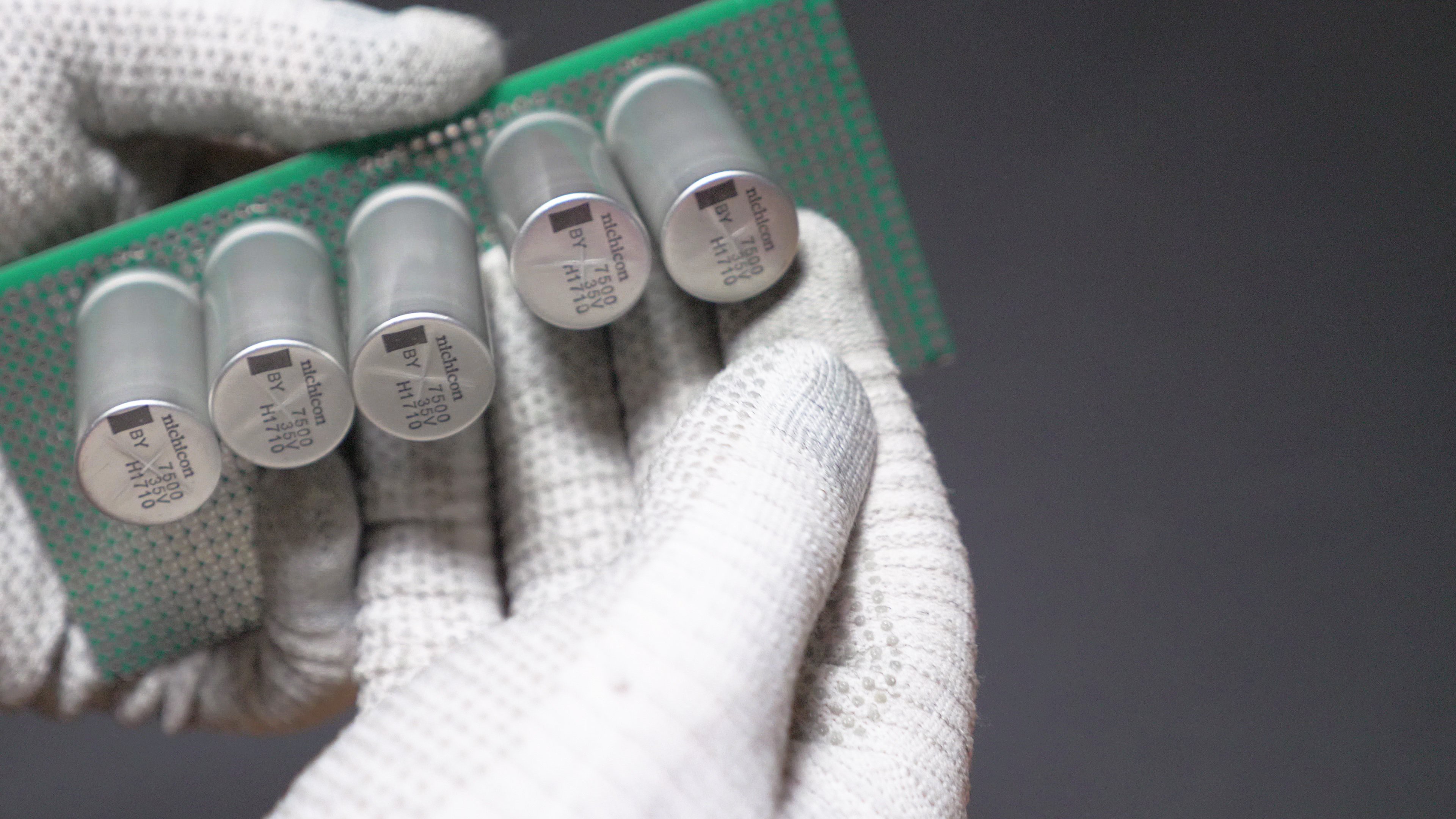
Because we are going to deal with extremely high welding currents, we need to have sturdy connections between capacitors. I am going to use 19 x 7500uF 35V Nichicon UBY capacitors.
All capacitors need to be connected in parallel. Shape and of the capacitor bank can be different depending on the type of case, or type of capacitors that are used, but in any case all positive leads need to be connected together and all negative leads need to be connected together. Leads of capacitors on the left and right side needed to be bent and twisted a little in order fit in my case.
The following illustrations shows how the connection is going to be made, and where the charging wires and high current welding wires will be connected later:![]()
First I'm going to insert the capacitors to a double-sided perfboard with metallized holes, pre-cut to the appropriate size.
![]()
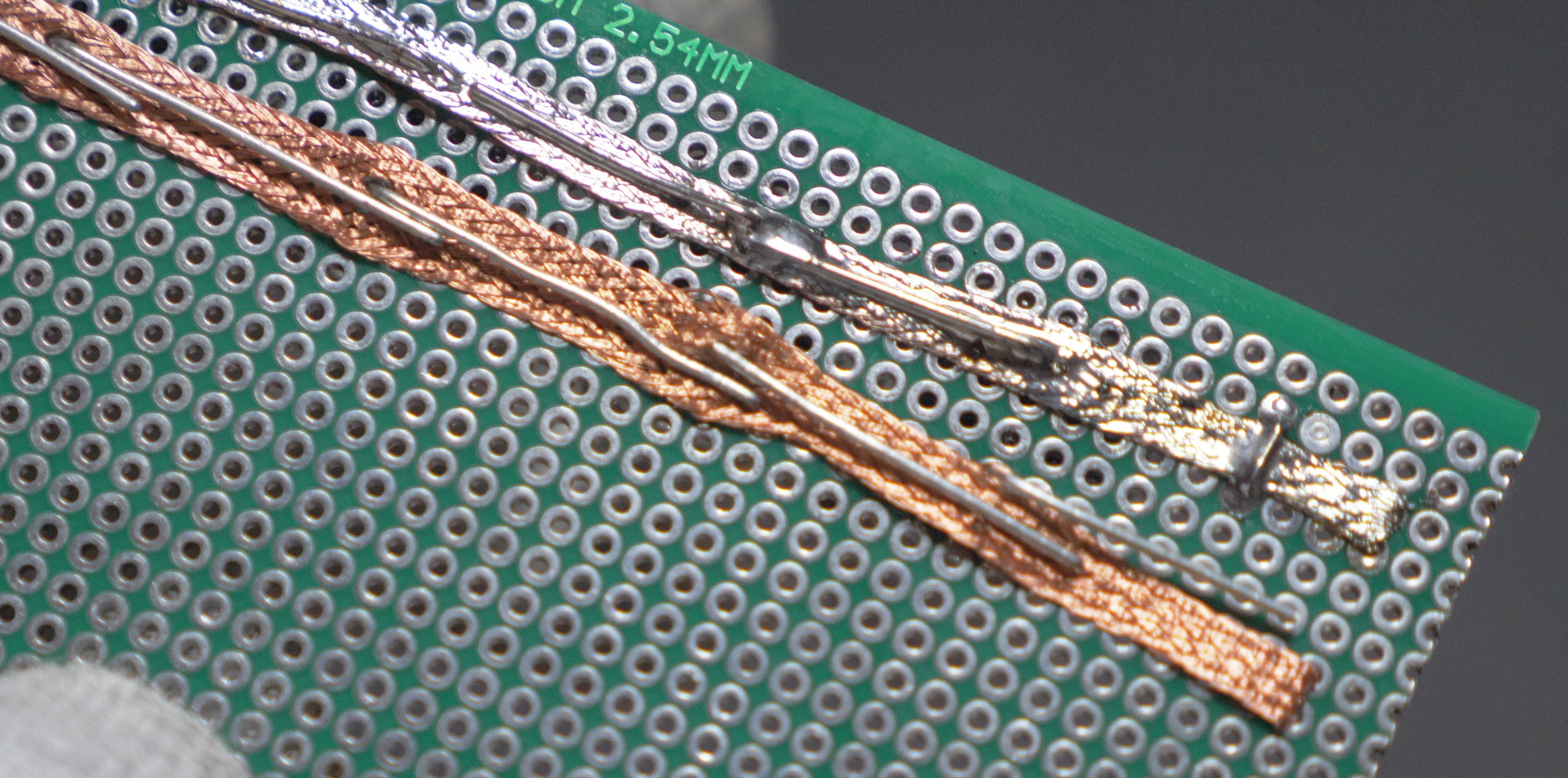
I am using some pieces of copper wick to enhance the current carrying capacity:
![]()
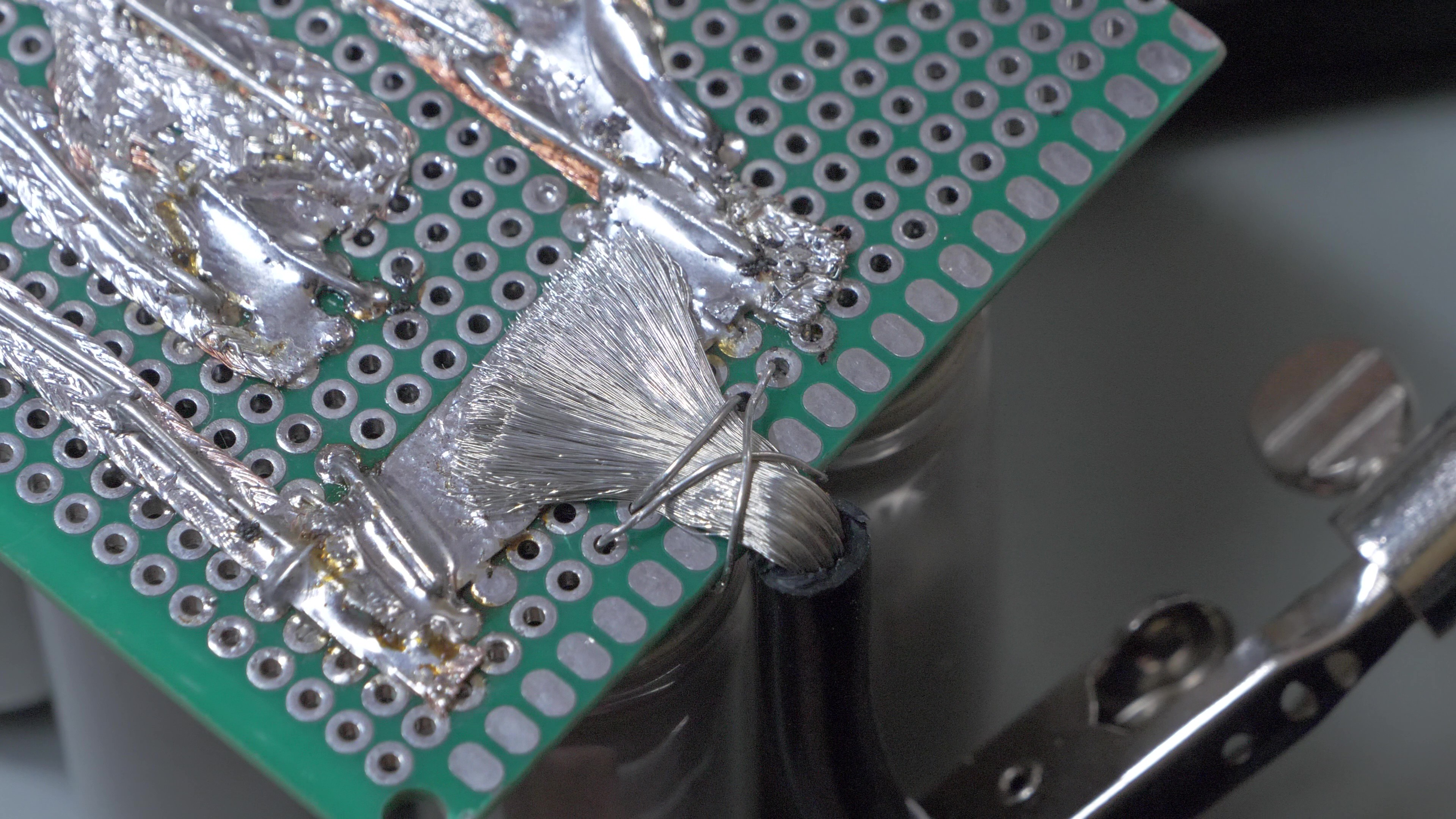
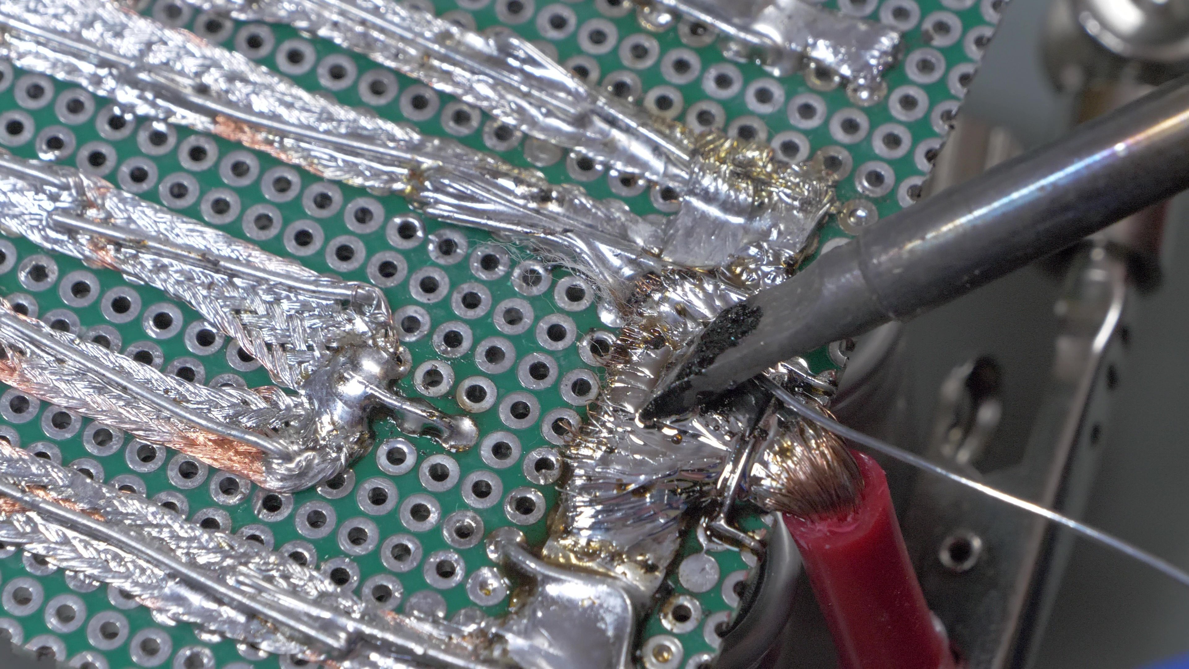
After the copper wick has been pushed through the legs of capacitors, I bend the legs and apply fair amounts of solder. This process needs to be repeated for all rows of capacitors. Please mind the polarity! The capacitors need to be connected in parallel.
![]()
![]()
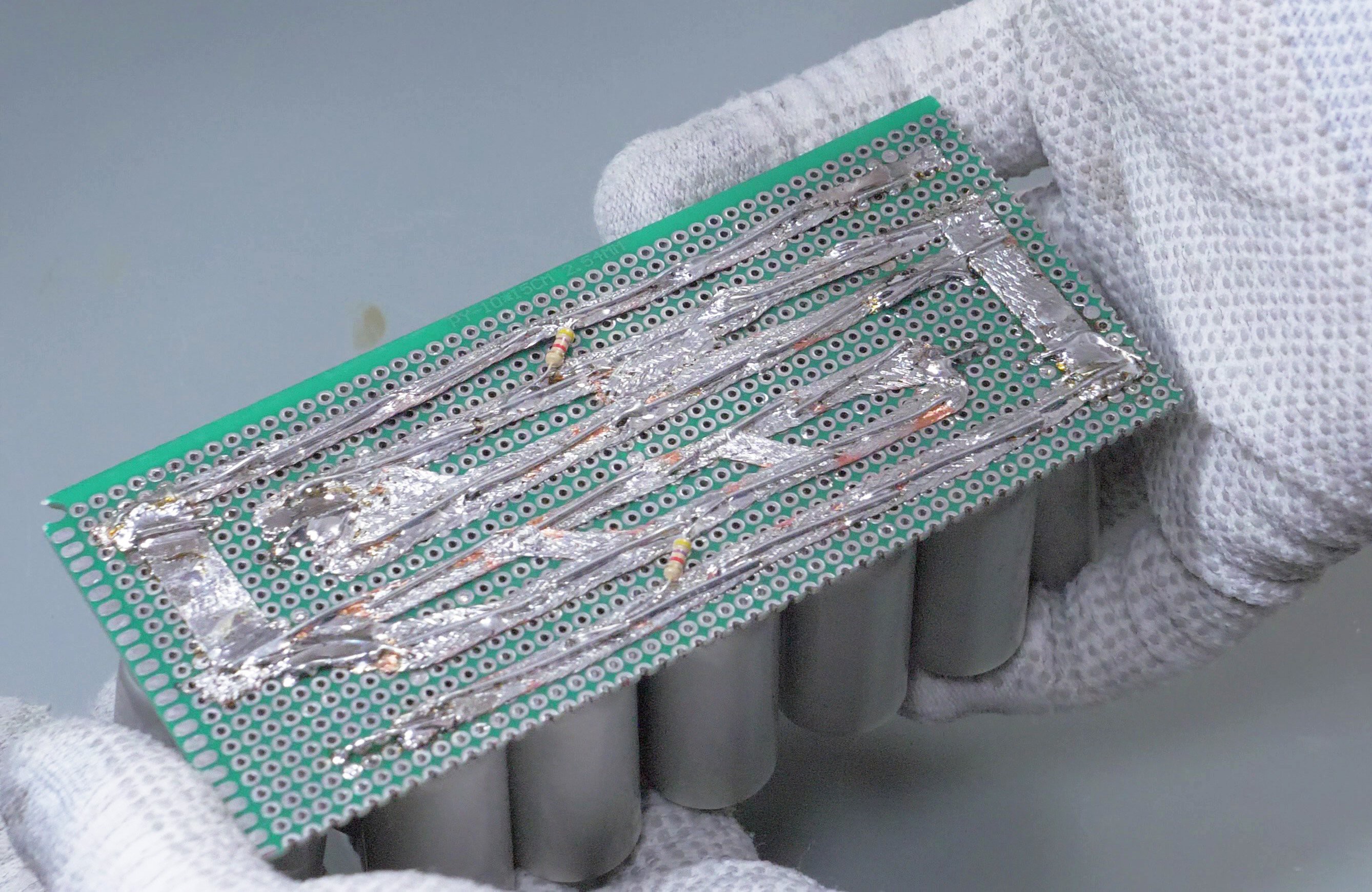
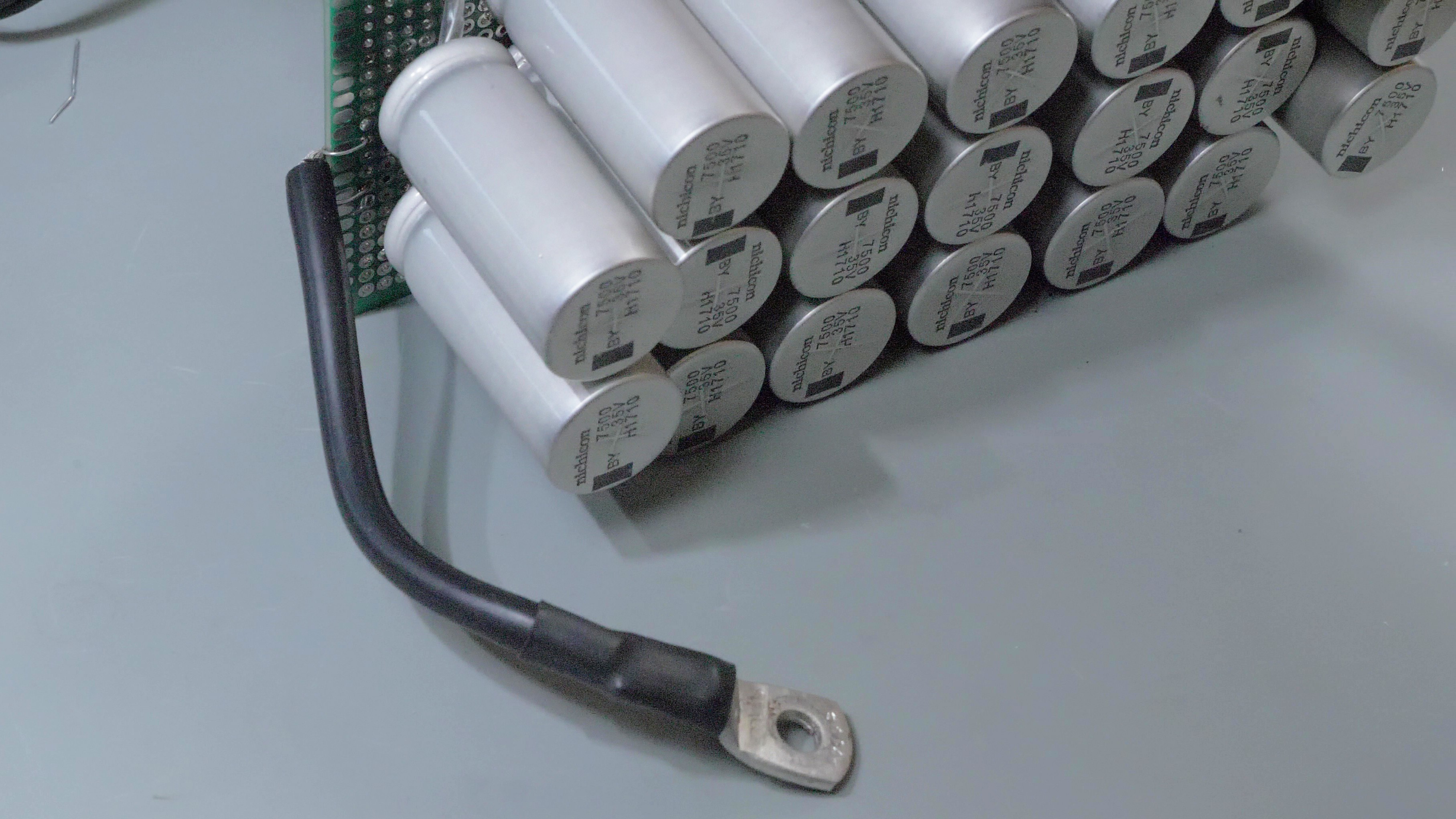
This is how a soldered capacitor bank should look like. It might look a bit different depending on the amount and size of the capacitors. I also added high-value bleeder resistors which will force the capacitors to discharge over time (which is good for safety and also allows quicker voltage adjustments if the voltage is stepped down). Note the thicker copper areas on left and right sides: cables will be attached here in next steps.
![]()
-
2Modifying the relay module
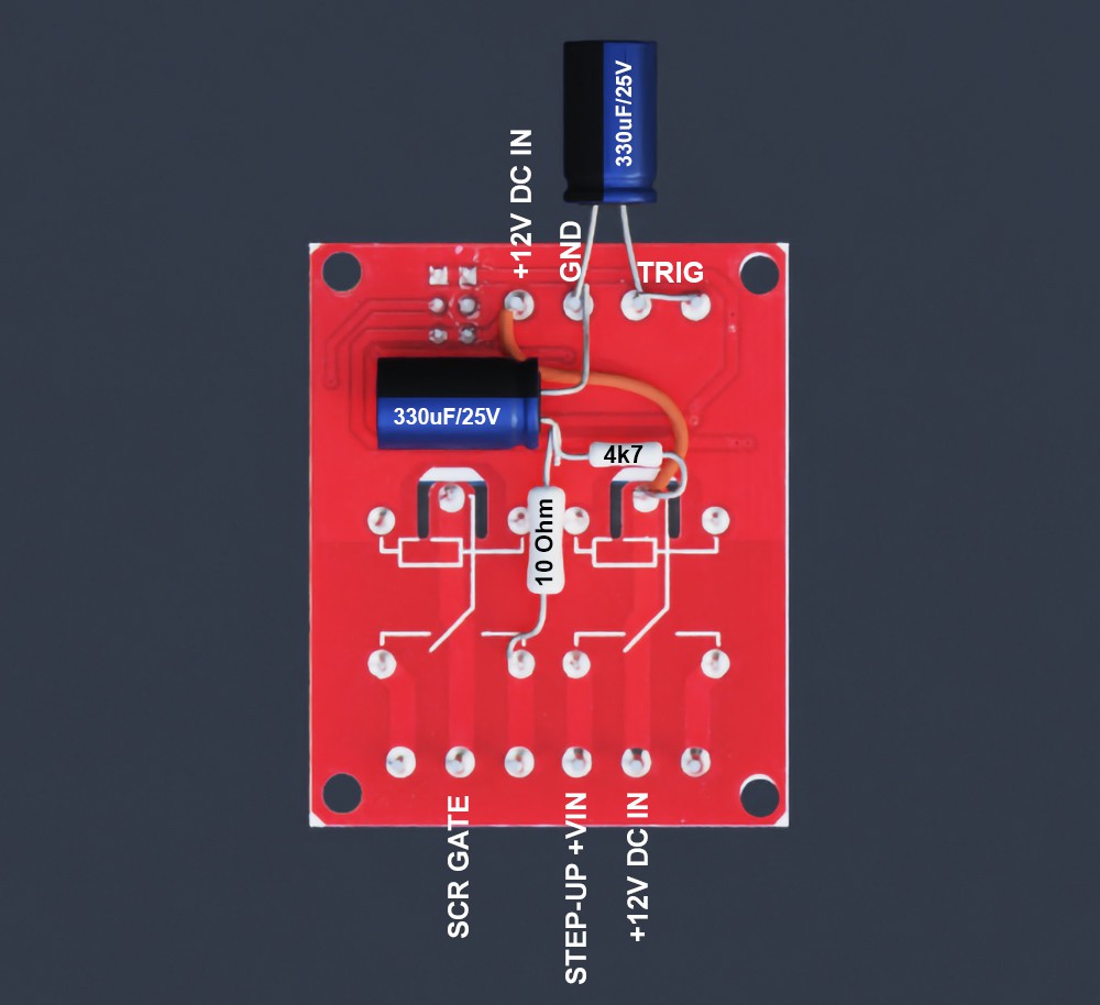
This is how the bottom of the HW-279 relay board should look after the modification. You need to make these modifications if you want to make this spot welder using off-the-shelf modules. If you want to make a custom PCB instead, you can skip this step and proceed with building a custom PCB.
![]()
Four components are added: two capacitors and two resistors.
First capacitor is added between GND and TRIG pins (TRIG turns the relays on). It will cause the relays to turn off with a delay (around one second). This is needed to make sure that the capacitor bank has been completely drained before charging will start again. This capacitor doesn't need to be soldered, it can be pushed into screw terminals.
Second capacitor is soldered between GND and a junction between two resistors. This capacitor will store the charge which will be used to trigger the gate of the SCR. When the relay is turned on, this capacitor will be discharged into the gate.
First resistor is 4.7 kOhms, which is used to "trickle charge" the capacitor responsible for firing the SCR gate. The resistance is high enough not to trigger the SCR gate by this resistor itself (but a fully charged capacitor will trigger the SCR).
Second resistor is 10 Ohms, 1W. It adds some resistance between SCR gate and capacitor, to minimize the chance of sparks and sticking of the relay contacts.
-
3Preparing the wires and cable connectors
Now 10 AWG silicone wires need to be attached to the positive and negative tabs capacitor bank. Before soldering, I wrapped the stripped ends with some additional pieces of wire to make them stay in place. Then I applied some solder to the wires.
![]()
![]()
![]()
After soldering, the burnt flux can be cleaned with isopropyl alcohol.
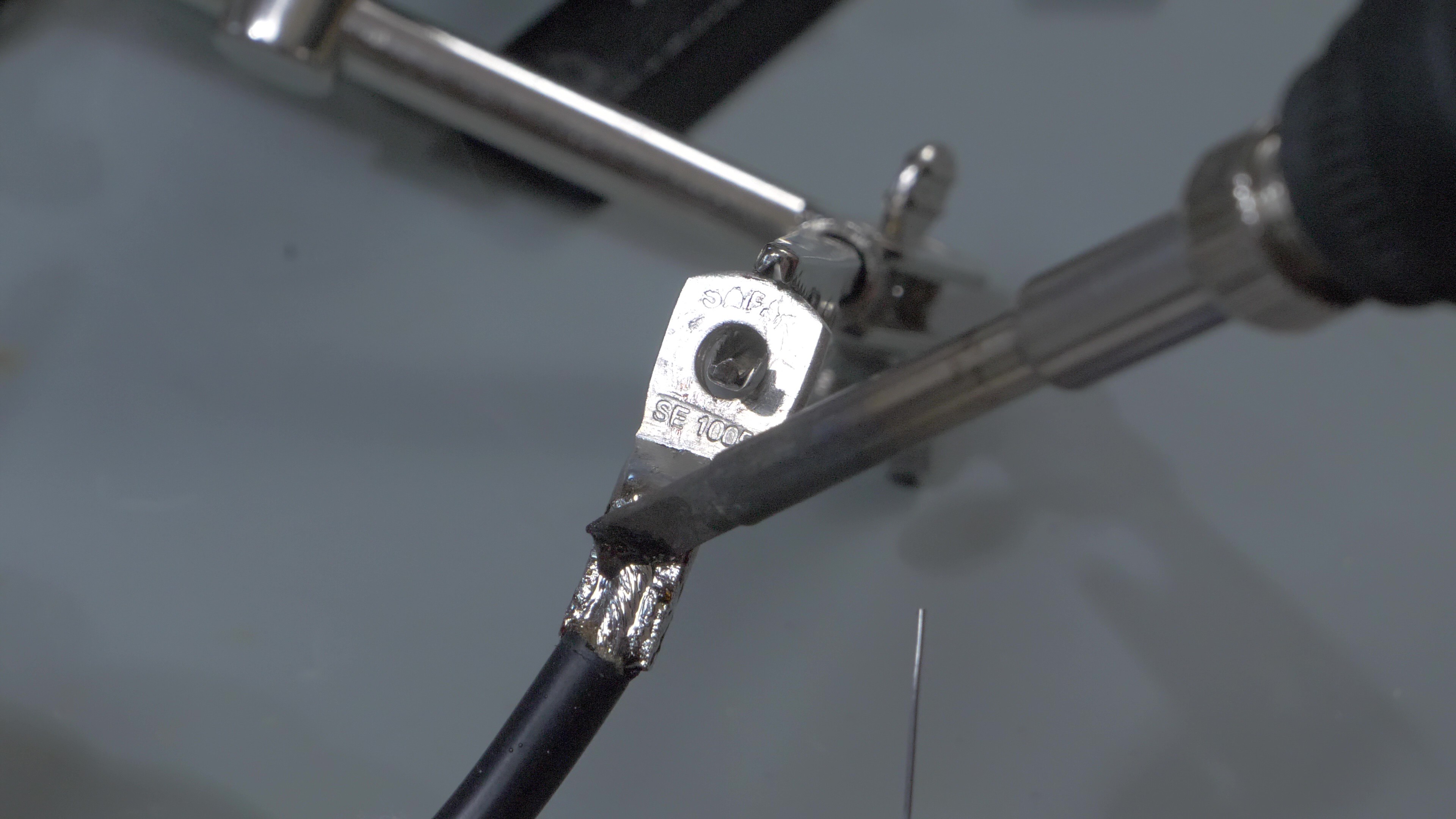
Now the negative wire needs to be terminated with a cable lug (5mm diameter hole). I didn't have a proper press, so I cut out the top of the cable lug and soldered the wire, instead of crimping it. Remember to insert a piece of heatshrink before soldering.
![]()
This is how the negative cable should look like after soldering and applying the heatshrink.![]()
Another short cable (negative/black) needs to be prepared, with one side terminated with a wire lug. The positive (red) cable remains unterminated for now.
![]()
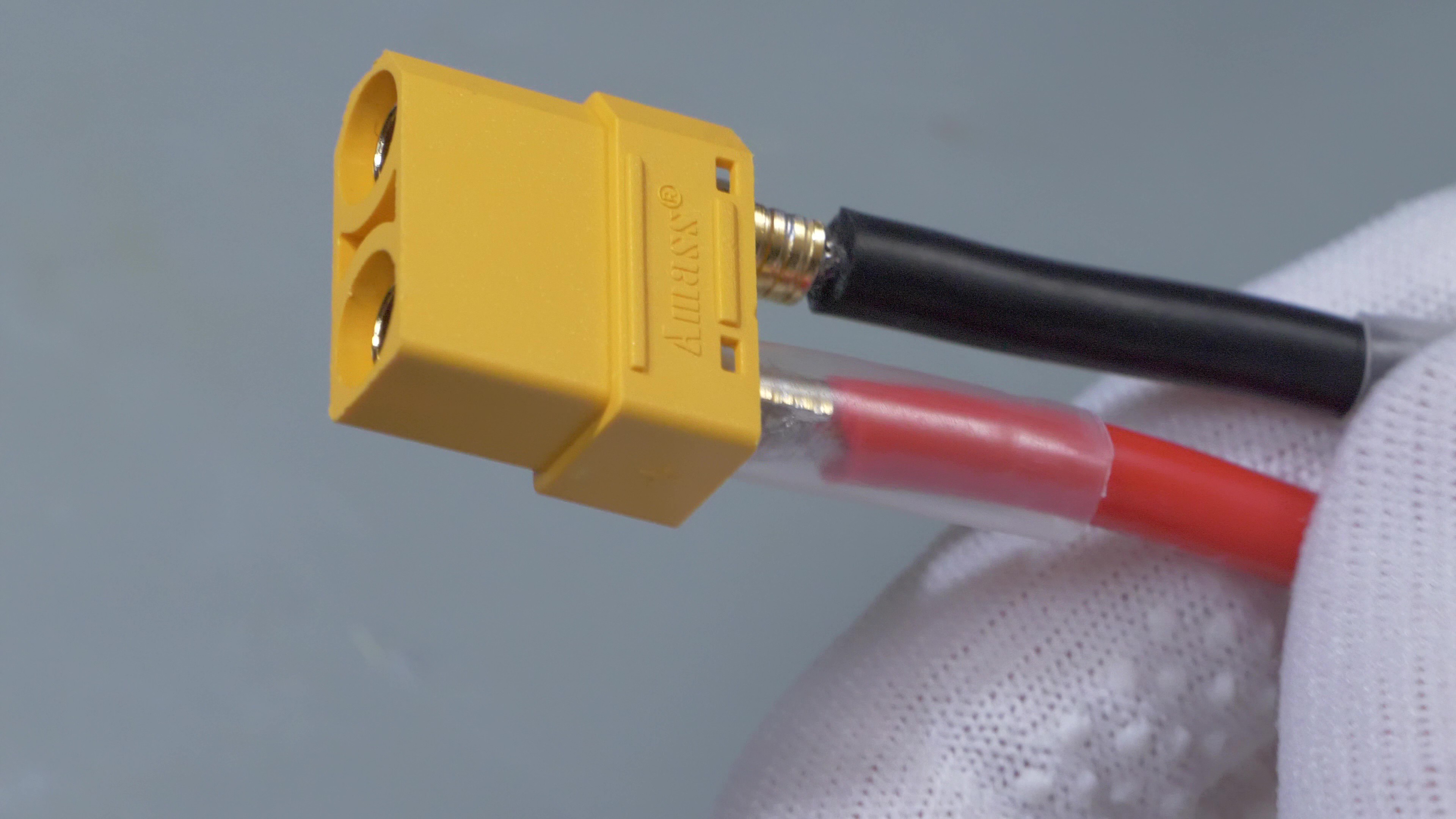
Now an XT90 connector needs to be soldered to the stripped ends of positive and negative cables. This is where the welding probes will be connected later.
![]()
-
4Preparing the welding electrodes
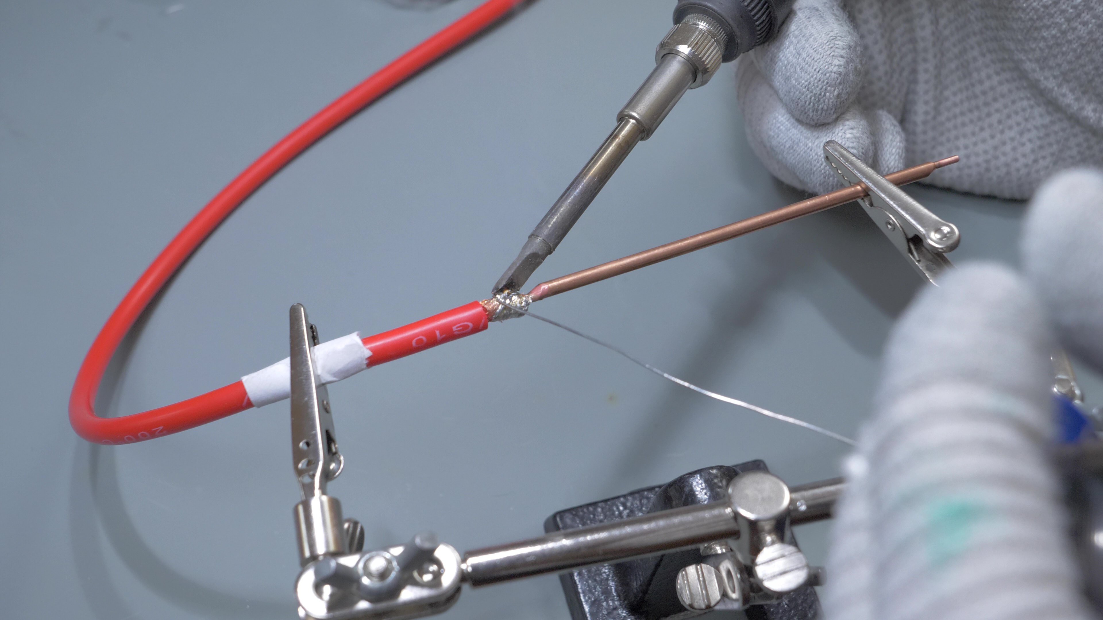
Two 3mm diameter copper rods with fine tips are going to be used as welding electrodes. An 40-cm long piece of AWG10 silicone wire needs to be soldered to each of them, I used red wire for one electrode and black wire for the other.
![]()
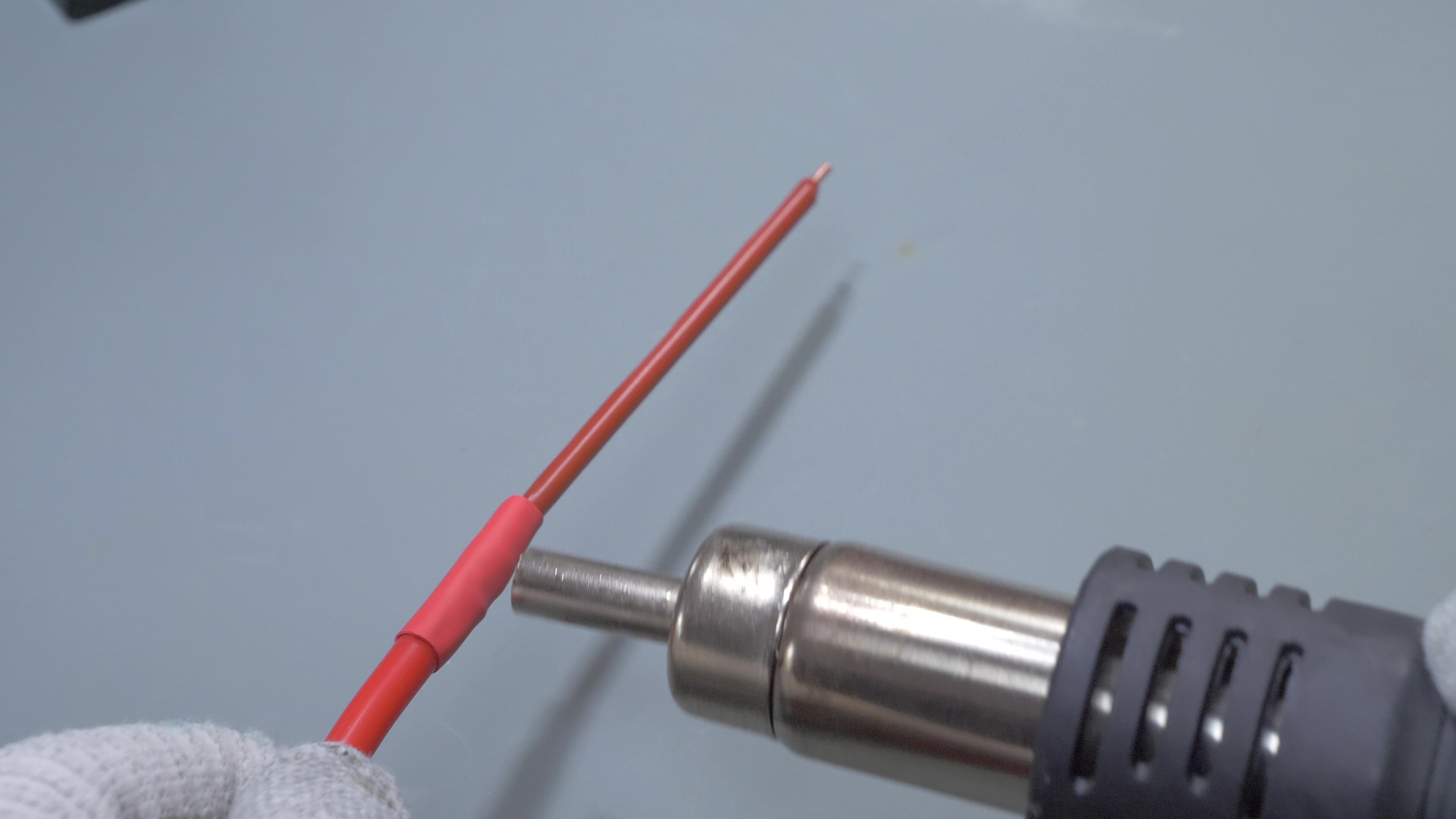
The heatshrink needs to be applied after soldering. Only the tips of the electrodes should be exposed.
![]()
Now the XT90 connector needs to be soldered. This is how the electrodes should look like now:
![]()
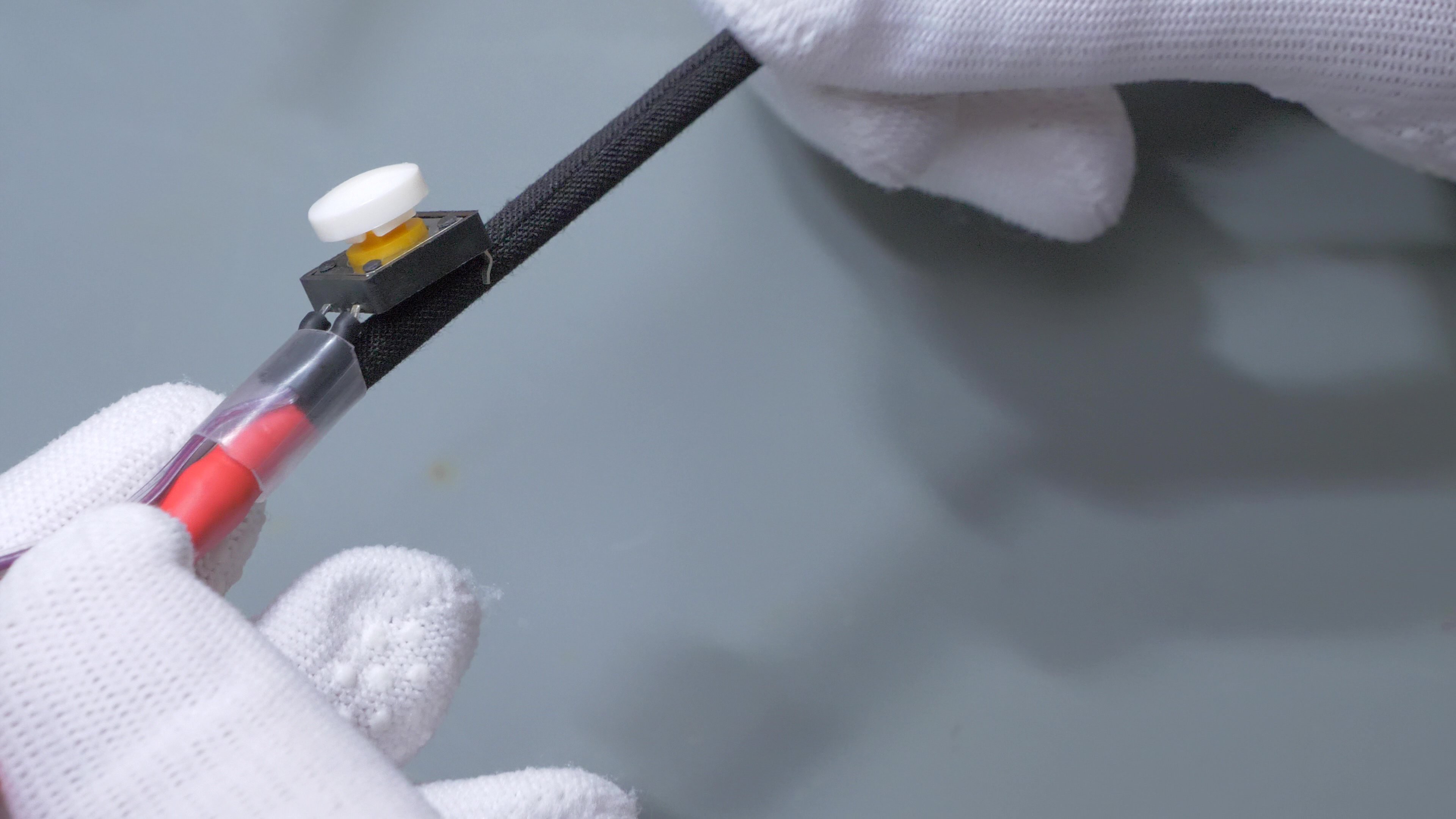
As a last step, the trigger button needs to be attached to one of the electrodes. A thin and flexible pair of cables and a small pushbutton will be needed.
![]()
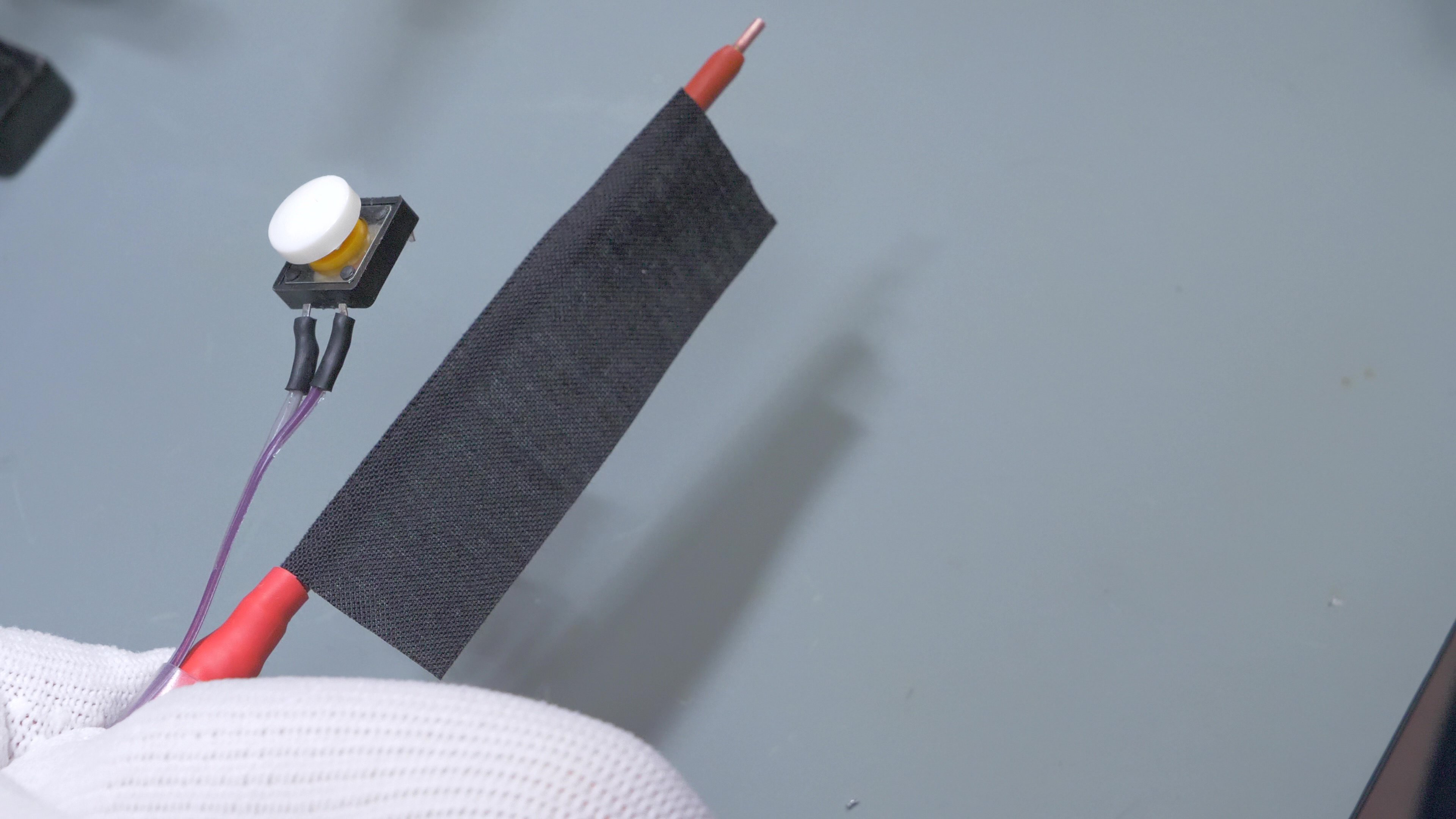
Before going further, I also wrapped some rough, textile wire bonding tape around the electrode, to make for a better grip.
![]()
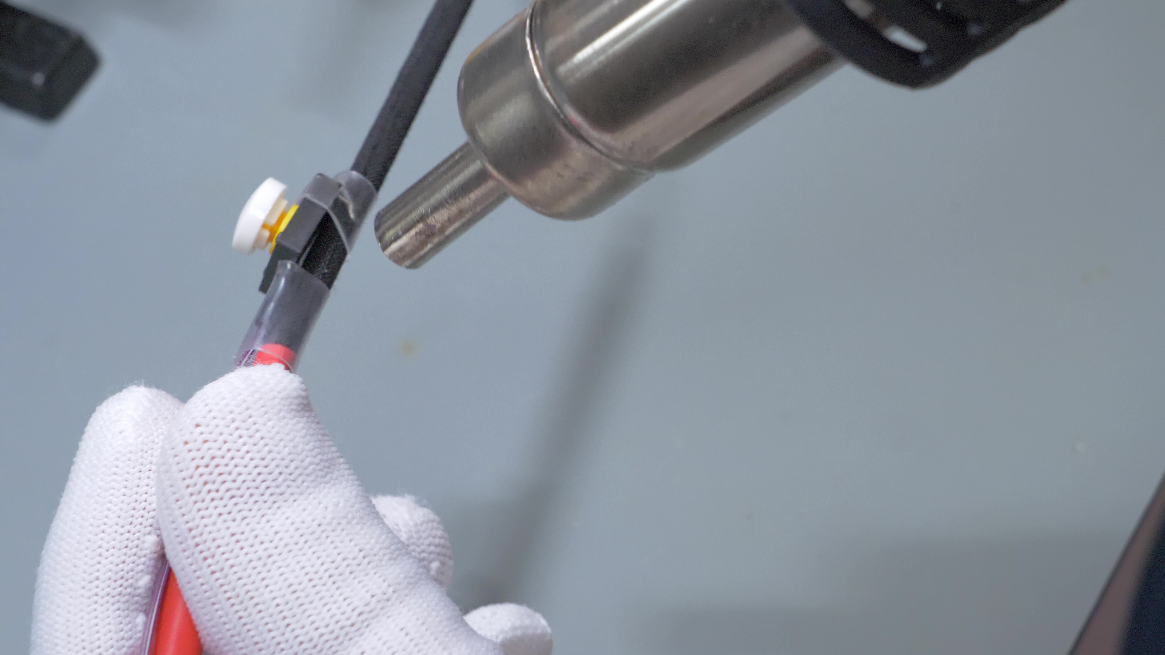
Now the pushbutton can go on the top of the electrode. It can be held in place with a piece of heatshrink tube.![]()
I also added a piece heatshrink for the other side of the button.
![]()
For extra strength, an additional layer of tape can also be wrapped around the pushbutton.
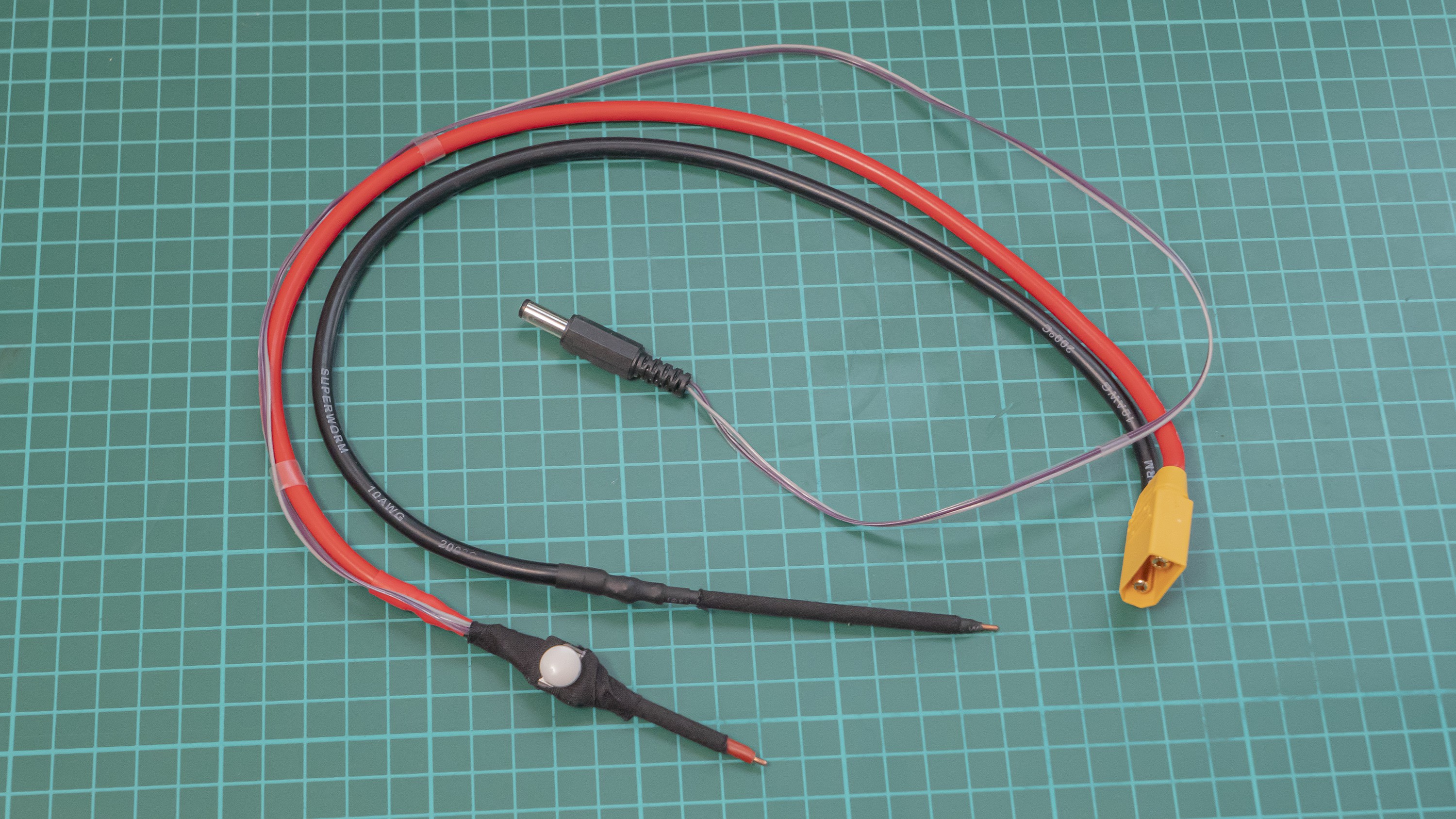
The wire coming out of the pushbutton needs to be terminated with a 5.5/2.1mm barrel jack connector. This is how the finished welding electrode set should look like:
![]()
-
5Adding external potentiometer to step-up converter
This step is optional, but recommended: it will allow to easily change the capacitor bank voltage, and thus spot welding energy, with a panel-mounted potentiometer. If this step is ommited, the voltage and welding energy will be fixed.
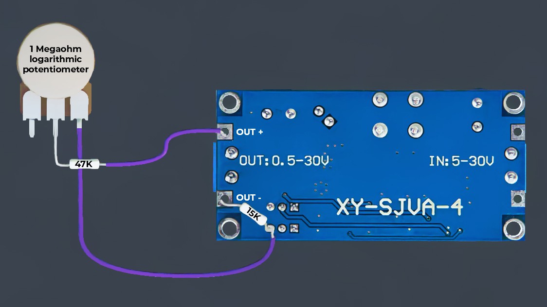
Two wires need be soldered to a 1 Megaohm logarithmic potentiometer. One wire will have a 47k resistor soldered in series and will go to the OUT+. Second wire will be soldered to one of the pins of the buck converter's trimpot. One additional 15k resistor will also need to be soldered between OUT- and the second wire.
Here is an illustration which shows how everything needs to be wired:
![]()
After soldering resistors and wires, the converter needs to be powered on and adjusted. A voltage meter should be plugged into the outputs of the converter. CV trimpot on the converter needs to be adjusted in such a way, that the voltage will be 31V when the external potentiometer is maxed out.
-
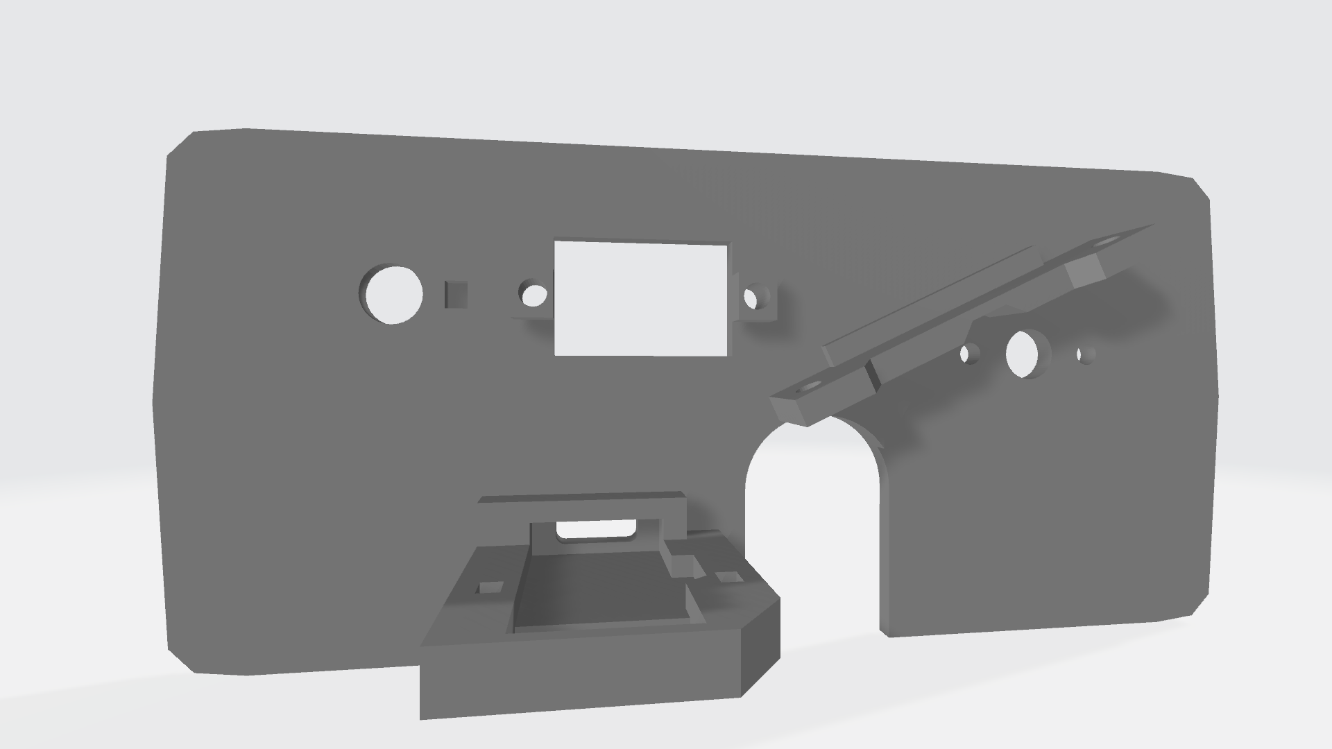
63D printed panel
A 3D printed panel will hold the relay module, USB-C power delivery input, potentiometer, trigger input jack and voltmeter display. STL files are attached in the 'Files' section. After printing, the modules can be secured using M2.5 screws (except the USB-C module, which can be secured using a small zip-tie).
![]()
Not-so-smart capacitive discharge spot welder
Portable spot welder that doesn't need microcontrollers, uses recycled industrial thyristor and mostly off-the-shelf components


Discussions
Become a Hackaday.io Member
Create an account to leave a comment. Already have an account? Log In.