-
Pulse oscillogram
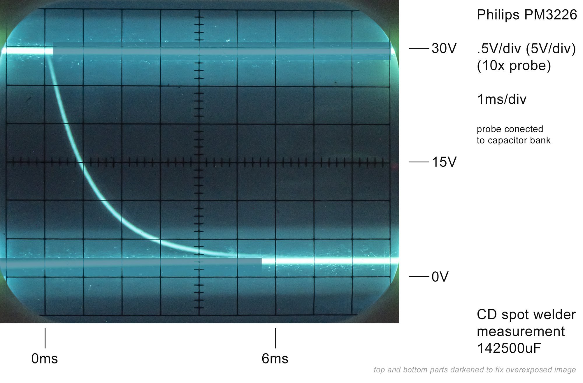
07/16/2023 at 13:42 • 0 commentsI managed to capture oscilloscope image of the pulse with an old analog Philips PM3226 oscilloscope. It was a bit tricky, as analog scope don't have digital storage capabilities, so I put a camera in long exposure mode and tried to capture the trace. I measured the voltage drop in DC mode. It worked, and the observations are as follows:
- Capacitors are discharged in 6 milliseconds
- voltage drops in half within 1 millisecond
- minimum voltage doesn't go to zero, but to around 2V (that's because of SCR threshold voltage)
The probe was connected to the capacitor bank as that was the simplest thing to do. The test was done while spot welding two nickel strips. I guess I could also measure the voltage drop across the welding lead.
If I get the math right (I entered discharge time of 0.001s from 30V to 15V into this calculator https://www.digikey.com/en/resources/conversion-calculators/conversion-calculator-capacitor-safety-discharge and got 0.01012418ohms) the pulse should be close to 3kA.
![]()
-
Video with commentary
11/06/2022 at 16:24 • 0 commentsThe video with commentary is finally ready. It shows how does this spot welder work and how to build one:
-
Assembly
10/08/2022 at 12:31 • 0 commentsThis animation shows how the spot welder components are packed into the case:
![]()
I used a 3D printed panel (white part, STL files are included in Files section) and a generic plastic case (150mm x 110mm x 70mm model 'Kradex Z3W'). The modules are held with M2.5 or M3 bolts and nuts, and M5 bolts were used to mount welding cables on SCR module.
Depending on your region you may need to use a case from different manufacturer and make some adjustment to the STL files. You can also make a case of your own, or even use the spot welder without a case.
-
Animated circut
10/06/2022 at 20:53 • 0 commentsI created an interactive animation of a simplified version of the circuit using https://www.falstad.com/circuit/ website. It shouldn't be treated as an accurate simulation, but it shows the general idea about how the welding pulse is triggered and how capacitor charging and discharging happens.
You can open the circuit in your browser by following this link: https://www.falstad.com/circuit/circuitjs.html?ctz=CQAgj...
Step-up converter module is ommited here.
![]()
-
Initial welds
10/06/2022 at 16:02 • 0 commentsI did some initial test welds with old AA cells, old coin cells and 0.1mm thick nickel strips. I started with almost maximum voltage (30V), but it's probably more than needed for 0.1mm nickel strips. This spot welder certainly has enough power to serve its purpose. I will need to find optimal voltage settings for various nickel strips.
![]()
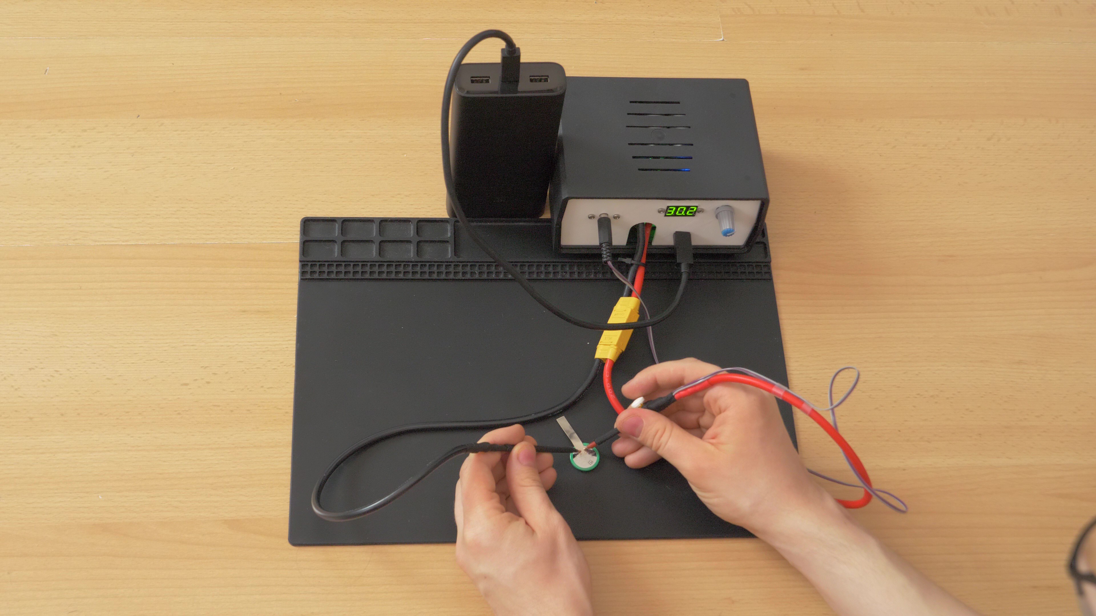
Spot welding test with a coin cell. Welder is powered off USB-C powerbank. ![]()
You can see how the voltage is instantly reduced to zero and goes up when the spot weld is done. This is a close-up look on one of the first spot welds.
![]()
![]()
I was able to hang around 1 kg of weight (1 litre of water) on the metal strip welded to the AA test cell.
![]()
I needed pliers to remove the nickel strip from the cell. You can see that parts of nickel were torn off and there are holes left on the nickel strip, and there are also remaining bits of nickel attached to the cell. This is good, because it means that the welding was pretty strong.
![]()
I only tested small AA and coin cells for now, because that's what I'm mostly going to use with that spot welder (rebuilding Ni-Mh battery packs for older devices), however it would probably work well with Li-ion cells too.
-
Simplified schematic
10/06/2022 at 00:14 • 0 commentsEven though I am mostly using off-the-shelf modules (with some modifications) in this project, maybe it would be also a good idea to have an option to build this spot welder with custom-made, purpose-built PCB. For now I created a simplified schematic which should demonstrate how this device operates. I re-created the relay module using discrete components. However, the step-up converter module is shown as a "black box" for now. I will need to think about a suitable IC which could be used here. Current converter can charge the capacitor bank in around 4 seconds with 12V/3A input, which is a pretty good result. I thought about using MC34063 as a replacement, but it would be at least 4 times slower. And everybody knows it's ancient, but it's also very cheap and easy to be implemented. There are also more modern chips, which are better, but more difficult to implement and more expensive. I will need to evaluate all possible options and decide on something.
![]()
-
How it works, choice of components
10/05/2022 at 22:03 • 0 commentsHere is an illustration which shows components that will be necessary to build this spot welder:
![]()
To make a spot weld, quite a lot of energy will need to be dumped into a small spot in a very short amount of time. To store such amount of energy and to allow quick release of this energy, a bank of capacitors will be used. I used 19 Nichicon UBY 7500uF/35V capacitors connected in parallel, which have total capacity of 142500uF. I will charge them to only 31V at most, because some de-rating of electrolytic capacitors is almost always used, and it should increase the lifespan of these capacitors. 142500uF at 31V will give 64.19J of energy, which should be enough for battery tab spot welding. Each of these capacitors have ESR of 18 milliohms, which drops below 1 milliohm total after parallel connection. That will allow very high welding currents.
To release this kind of energy, some kind of extremely high current switch will be required. I wanted to use something that will be relatively easy to use, and I chose a second-hand industrial SCR (thyristor) module: T90RIA120. It handles peak currents over a thousand amps and doesn't require sophisticated drivers, unlike MOSFETs. There should be several similar second-hand thyristors which could be used to build such a spot welder. These industrial modules usually have wire terminals, which will allow for an easy installation.
Before we can weld anything, we need to actually get the energy from somewhere. Capacitors will need to be charged. For the ease of use, I decided to get the power from USB-C input. I used a small 12V USB-C PD trigger module, which will allow use of powerbanks and fast chargers. However, this is not enough yet. This capacitor bank would cause an extremely high inrush current, which would most likely trigger short-circuit protection in the charger/powerbank and the device would turn off immediately. Therefore some kind of current limiter will be needed. It would also be a good idea to step the voltage up, because it will allow for much higher welding energy. Therefore I decided to incorporate a DC-DC step-up converter CC/CV module, which will both increase the voltage and limit the current. I also added an external potentiometer which will allow to change the desired voltage easily. I also added some bleeder resistors to capacitor bank, to allow for quicker voltage changes. I also added a voltmeter module which allows for easy monitoring of the voltage.
The only thing that remains is a triggering circuit. There is one caveat associated with using a thyristor: once it starts to conduct, it will conduct until the current drops, even if we are no longer triggering the gate. Therefore i will need to use a circuit, which will simultaneously stop charging the capacitors and send a pulse to the gate of the thyristor. I decided to use an off-the-shelf dual 12V relay module for that pulse. However, I made some small modifications. I wanted to add some "cool-down" time after each welding pulse, so I added a simple timing capacitor to the trigger input. I also wanted to make sure that after each trigger button press only one brief pulse will be sent to the gate of the thyristor. To achieve this, I added a second capacitor which is constantly being charged, and once the trigger is pressed, it is discharged through relay contacts into the gate of the thyristor. This is important for safety reasons. The welding should only be triggered when both welding electrodes are touching the workpiece. If welding would be triggered when electrodes were in the air, and only after that they would touch the workpiece, a shower of big sparks would appear. However if we are sending only a single pulse to the gate of the thyristor, we should be safe in case of a user mistake, because the welding will happen only if everything is set up correctly when the trigger is first pressed. I will post details on modifying the relay circuit in follow-up instructions.
Not-so-smart capacitive discharge spot welder
Portable spot welder that doesn't need microcontrollers, uses recycled industrial thyristor and mostly off-the-shelf components