 Johann Elias Stoetzer
-
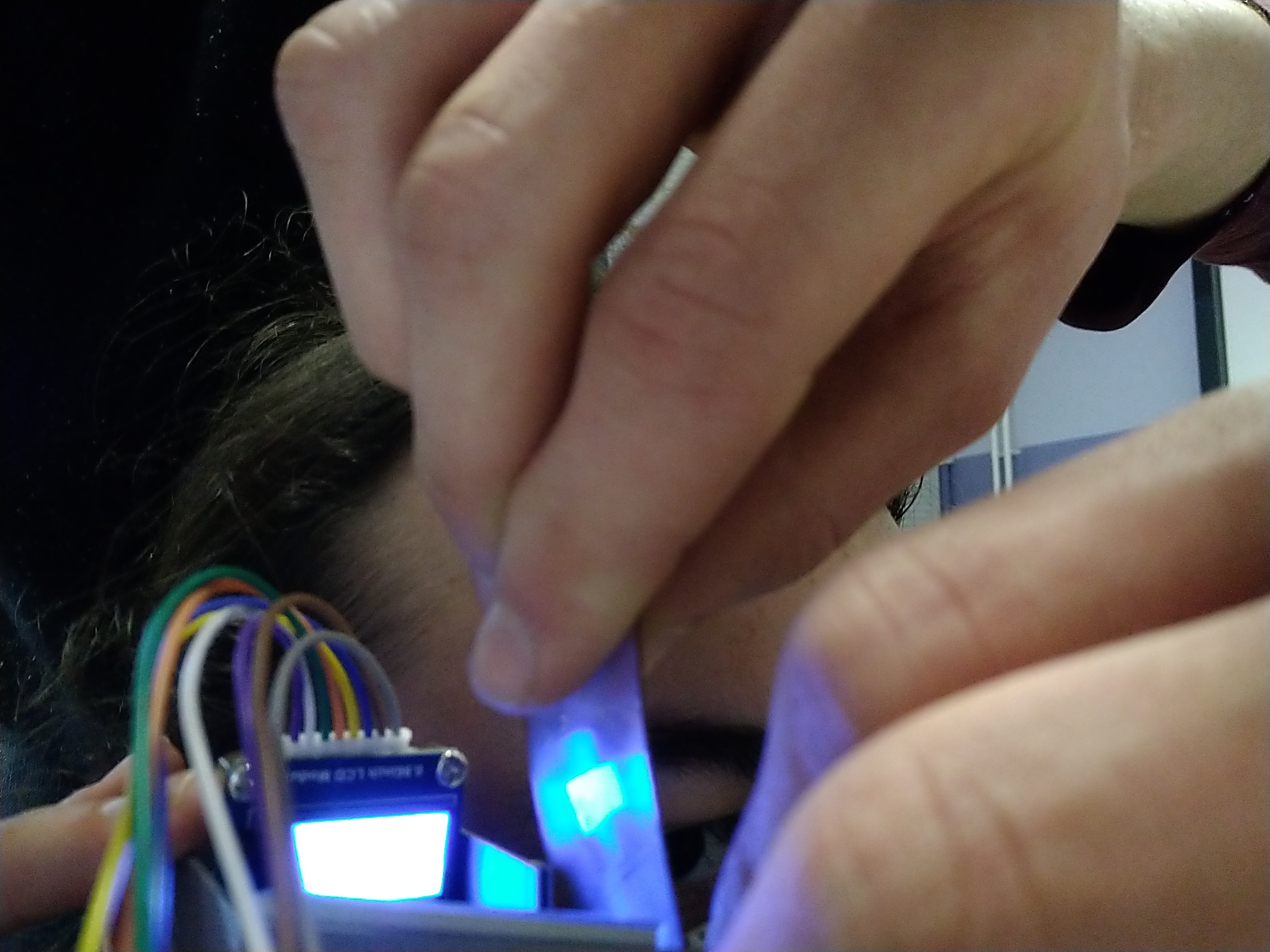
1AR thermal - prepare electronics
![]()
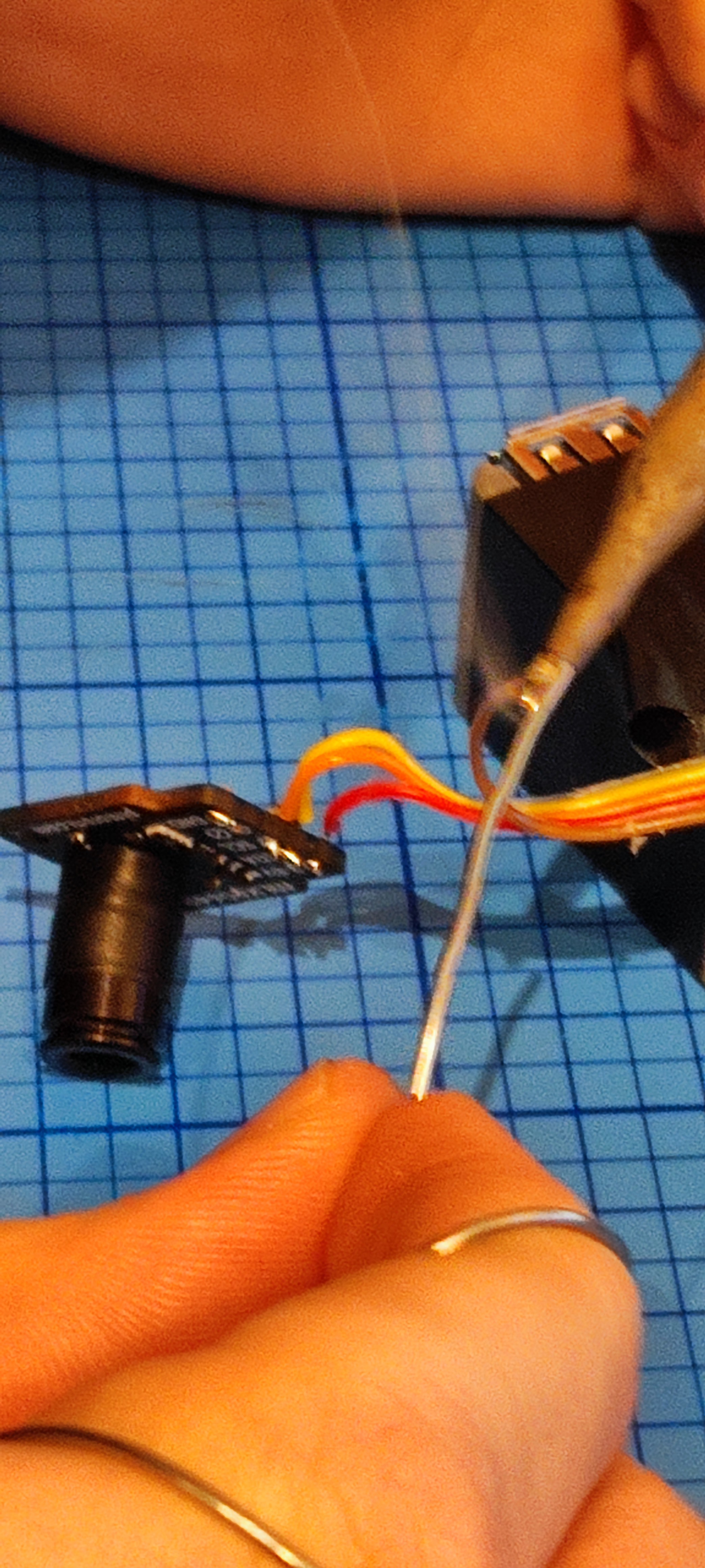
Solder cables for I2C communication to MLX 90640 and connect them to the Raspberry Pi.
You also need to adjust the max I2C speed in the boot-up script, otherwise the sensor cannot deliver the data fast enough...
Same for the display... the corresponding pins are named in the description - just solder (or connect them with DuPont-cables) to the SPI ports of the Raspberry.
This step is the same for both the AR thermal monocular and the AR thermal headset.
There are 2 versions of the MLX90640 with different lenses - we recommend using the tele one.
-
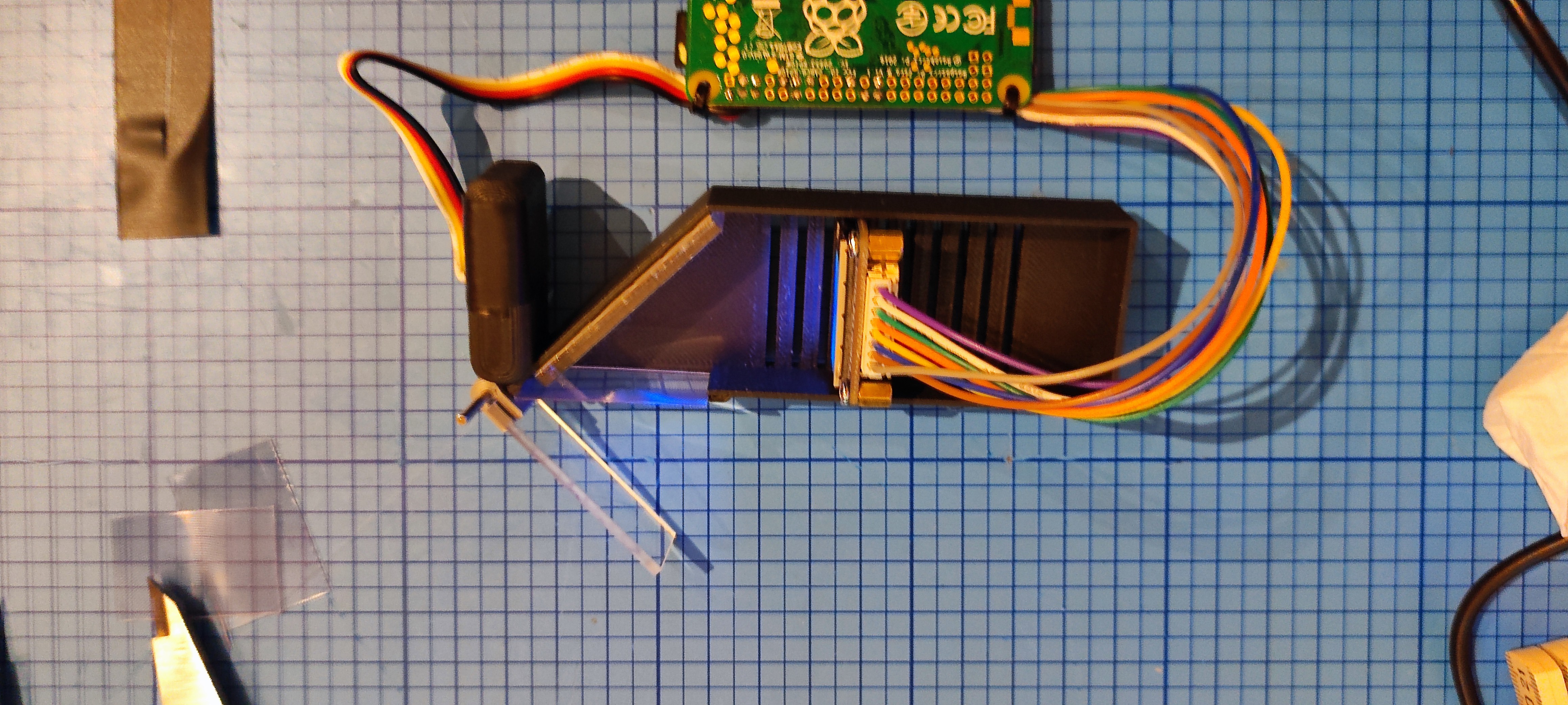
2AR thermal monocular - prepare 3D parts
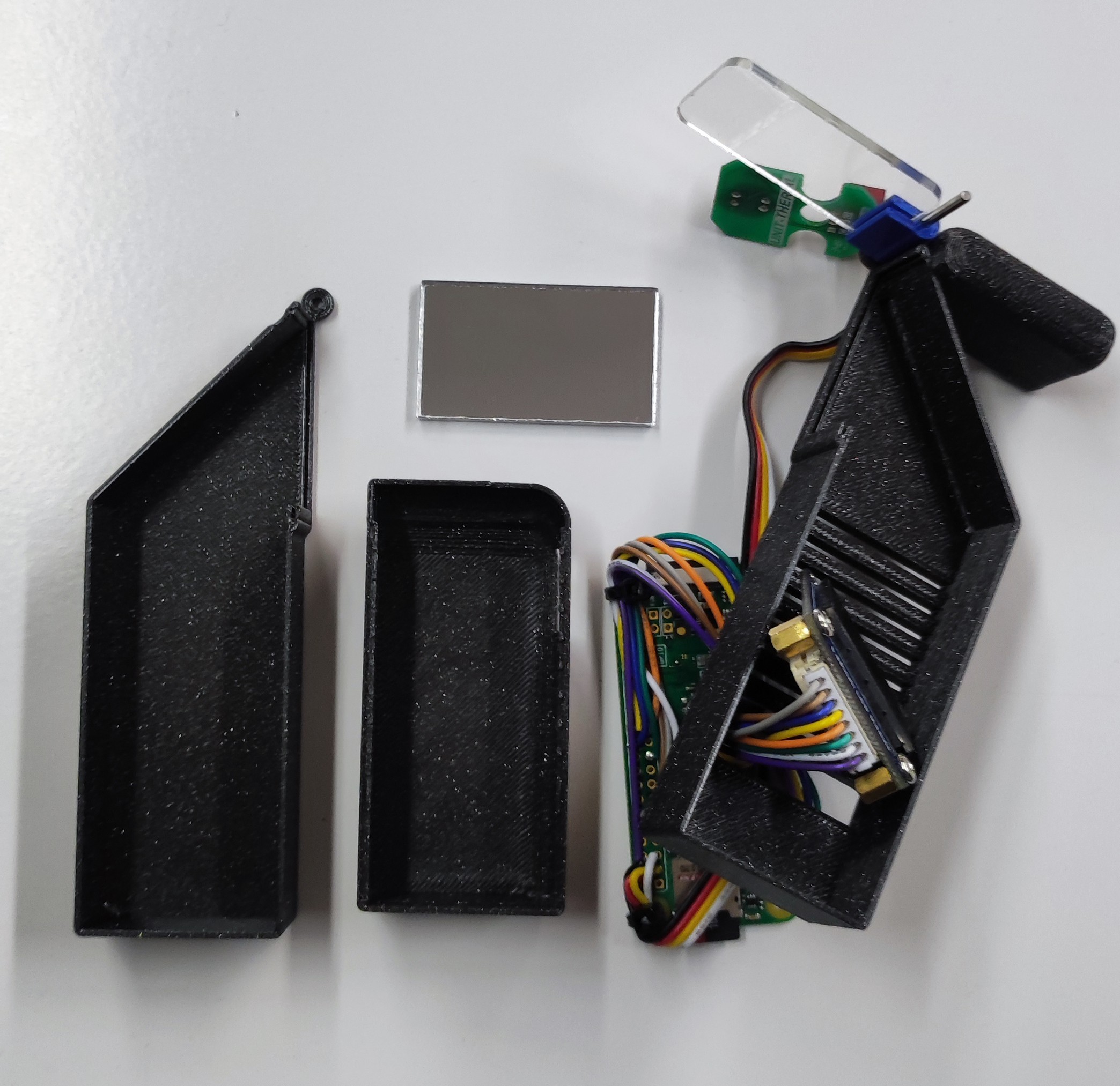
Once the electronic is ready and working, you can assemble everything in the case and adjust the correct positions...
![]()
The cutout in the frame should be big enough to get the plug for the display through... but better check this before soldering with your screen ;-)
We didn't provide the DXF files for laser cutting the mirror (mirrored acrylic) and transparent screen - because it's basically just rectangles. This should be fairly easy to set up with your laser cutter software or get it cut by other means...
-
3Adding mirror
This step involves a bit more testing - and depends for example on the lenses you want to use. We tried Fresnel lenses because they are just "flat" and can easily be cut to size! (We tried by Laser, it works, but actually, a cutter knife or scissors are easier).
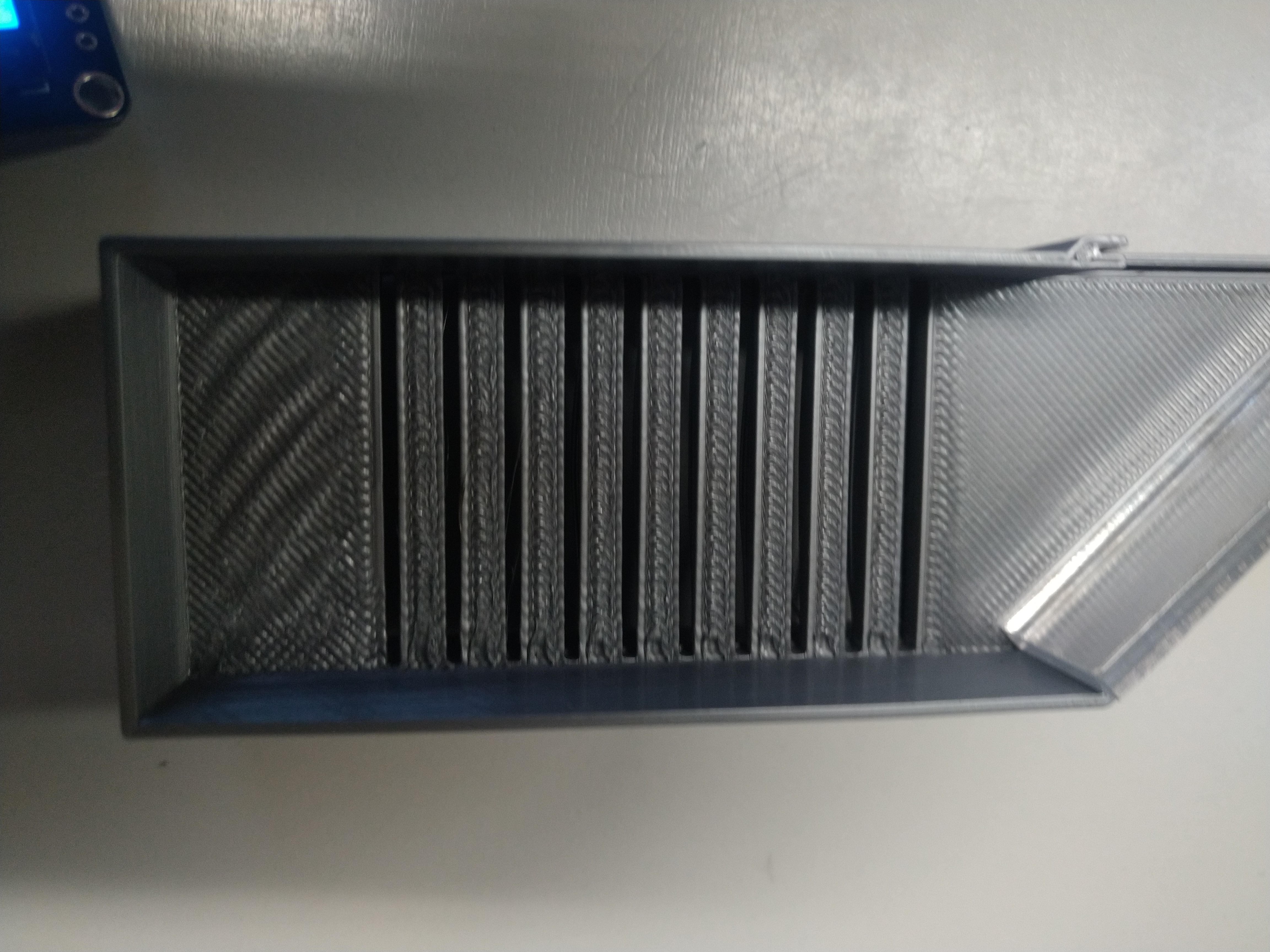
First, insert the mirror to the 45° angled side of the frame (there is a deepening for it).
![]()
(this is a photo from an earlier 3d-print, but you get the drift)
-
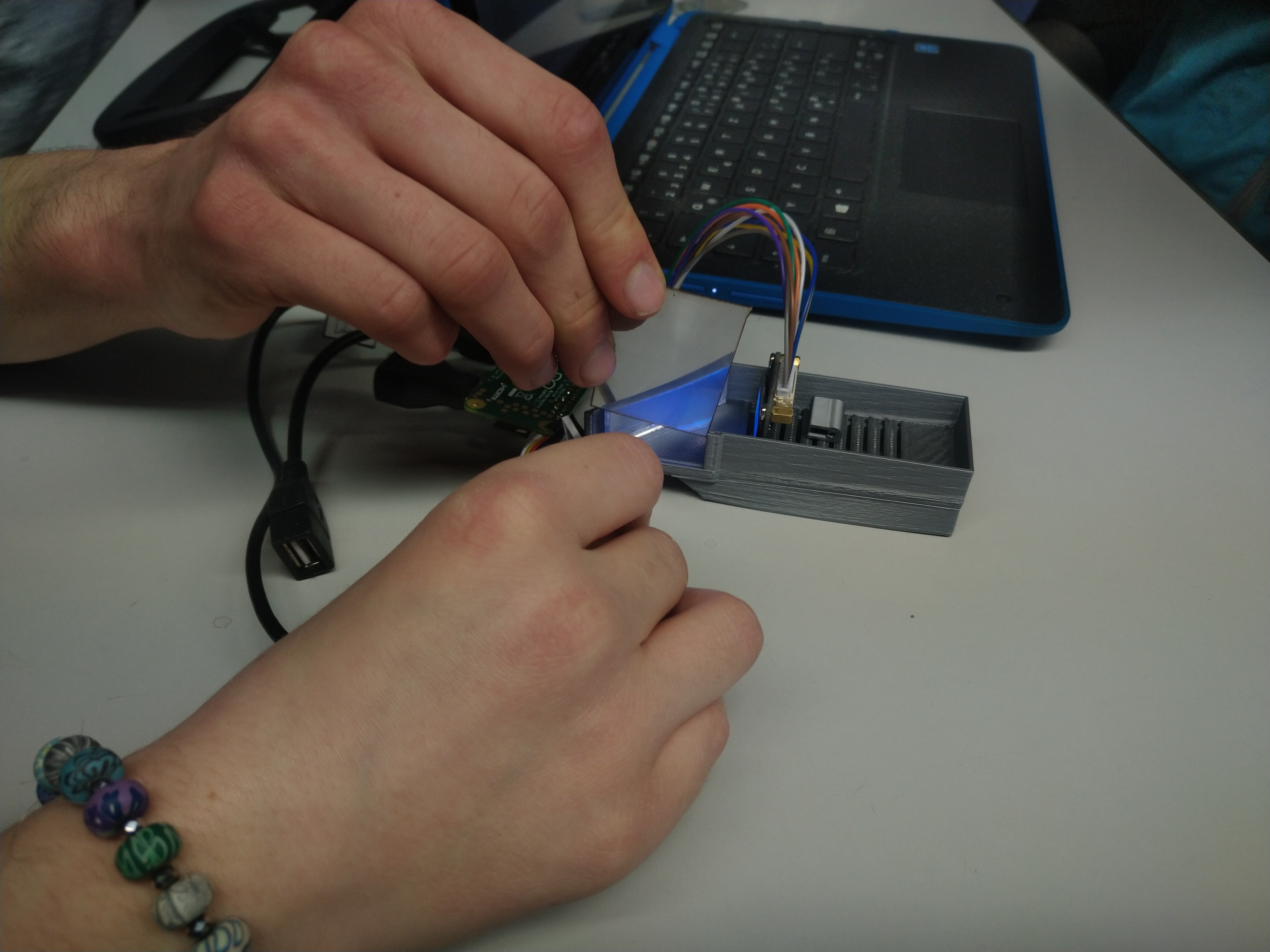
4adding screen and lenses
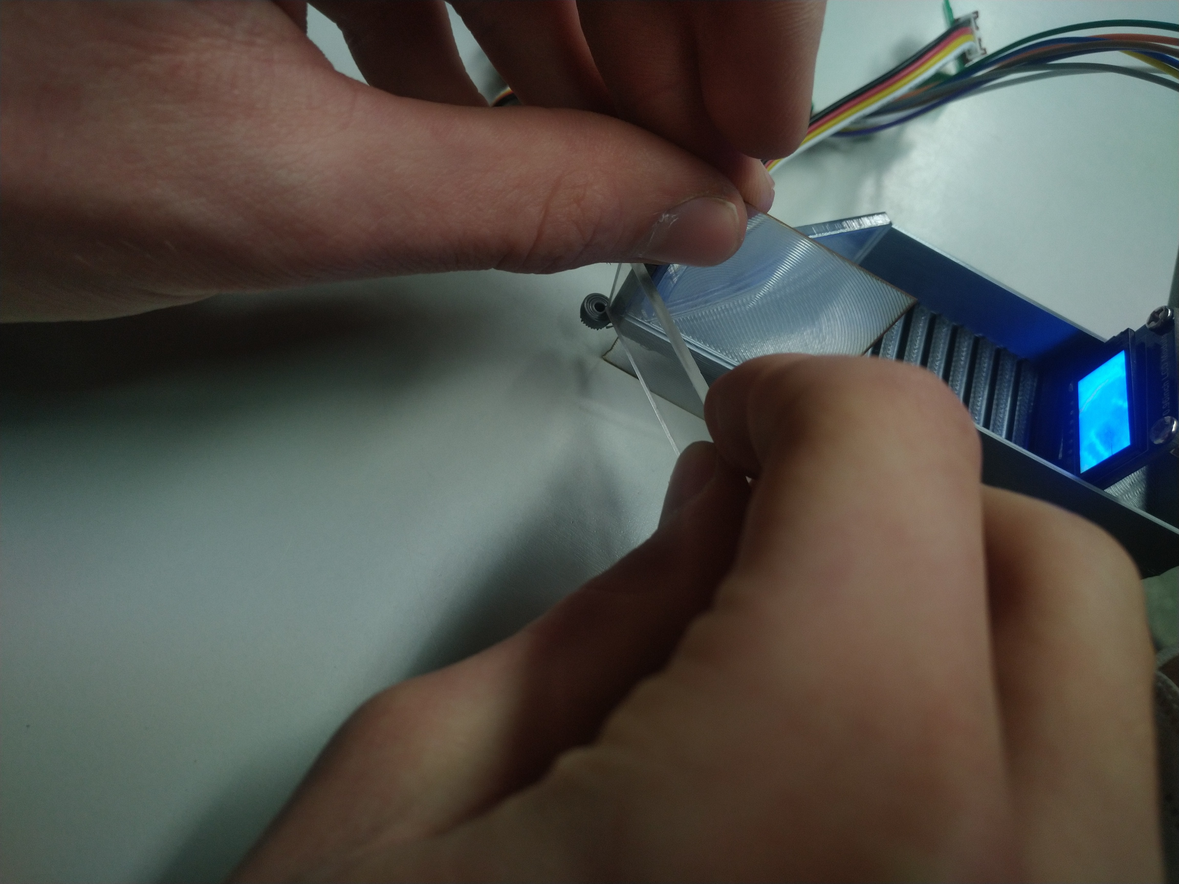
Now you can add the monitor and hold it in place with the help of teammates (best option!) or use some sticky tape...
![]()
and add the lenses... and the transparent screen
-
5Testing the right distances and positions
Now it is time to take a look through the transparent screen, adjust its angle, and check for the image of the small screen...
Is it big enough? If not, you can try adding another Fresnel lens or moving the screen more to the front. [our physics teachers would have known how to calculate everything perfectly in theory, we guess :-)]
![]()
-
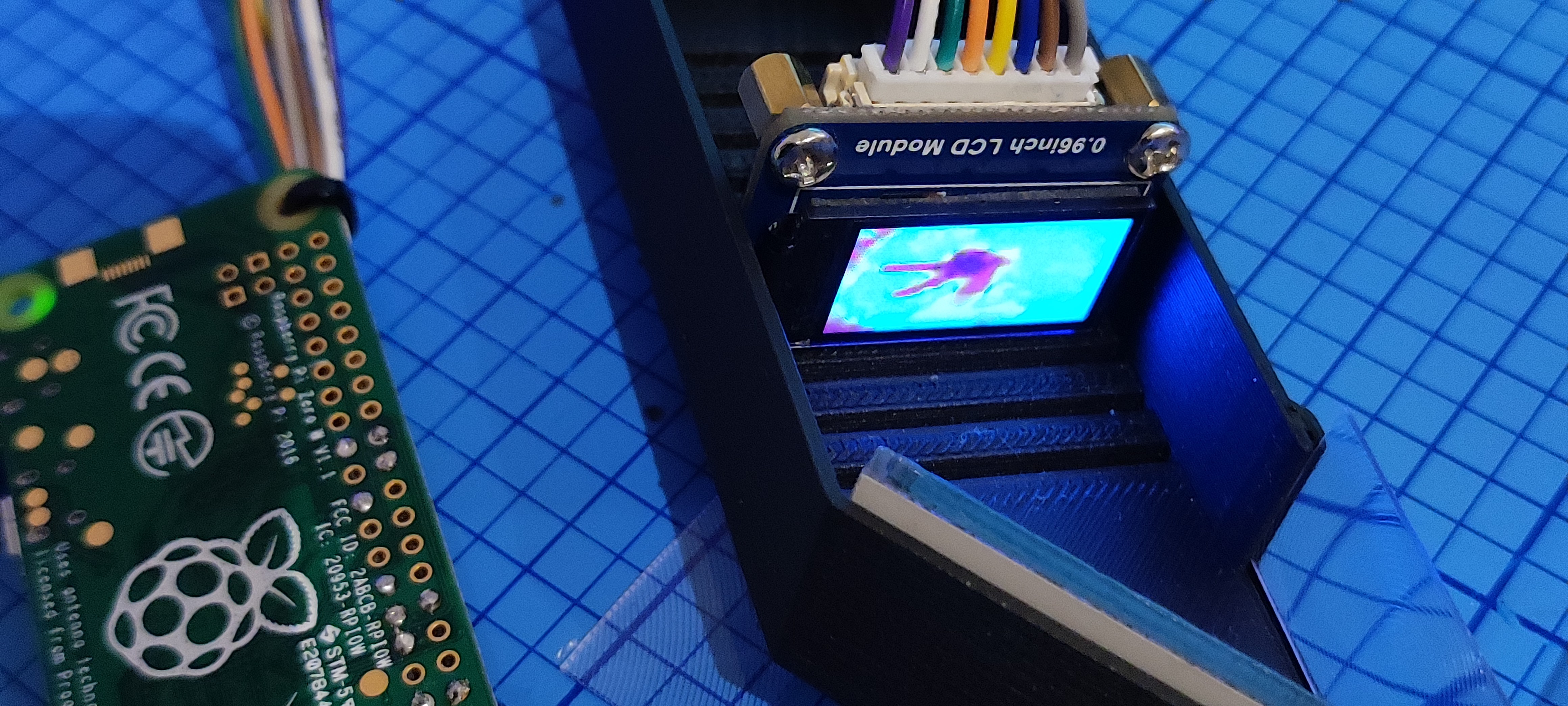
6Re-check everything is working fine -- and if the image is upside-down (orientation of monitor)
Once you have the distances right, check for the proper orientation of the monitor and thermal overlay in AR view:
![]()
![]()
-
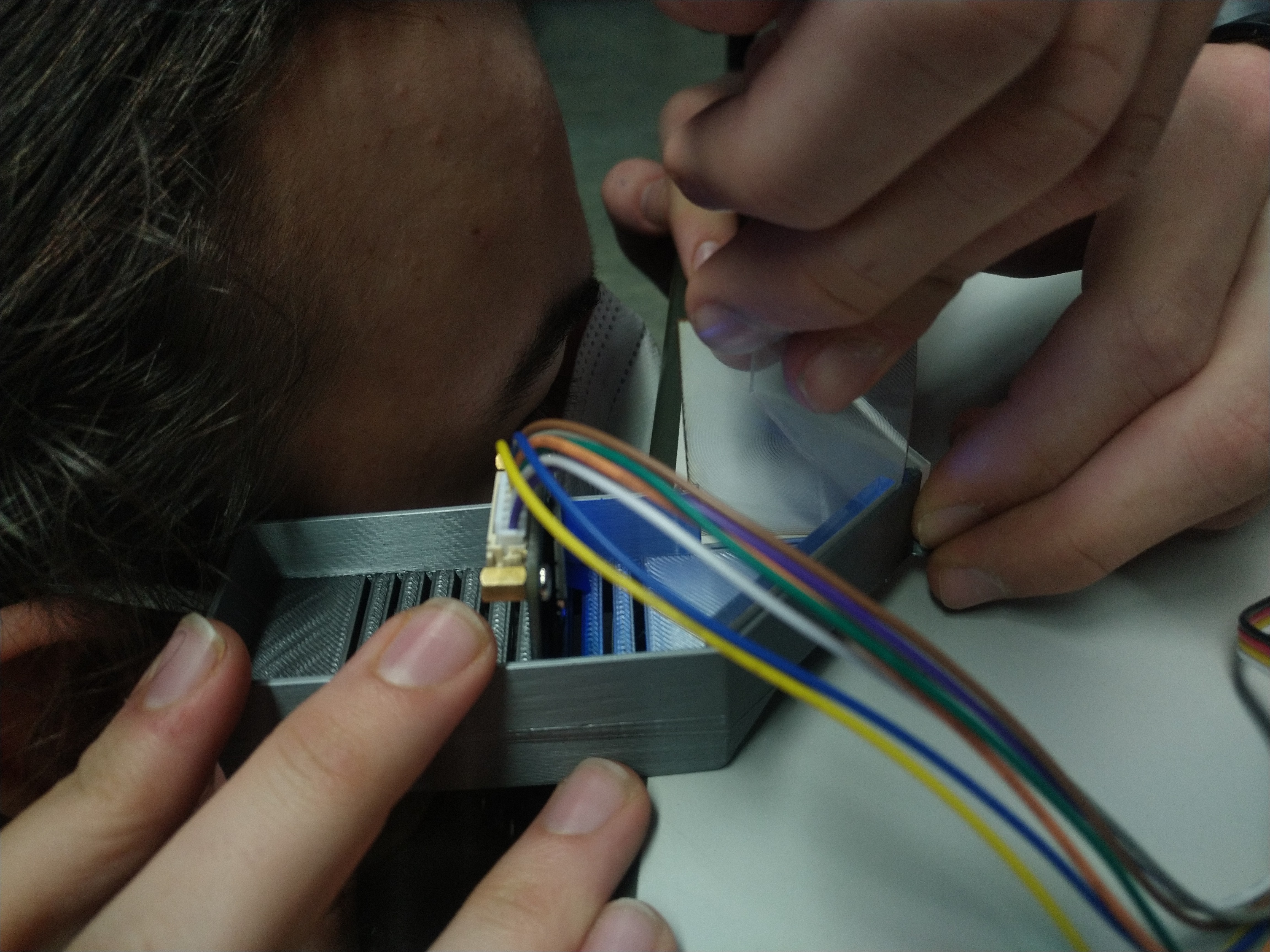
7Time for volunteers!
Now ask somebody to volunteer to look like a borg :-) and make final adjustments...
![]()
Here, we test if adding another lens improves the picture size of the thermal overlay...
![]()
No team-mates were harmed during the tests ;-)
-
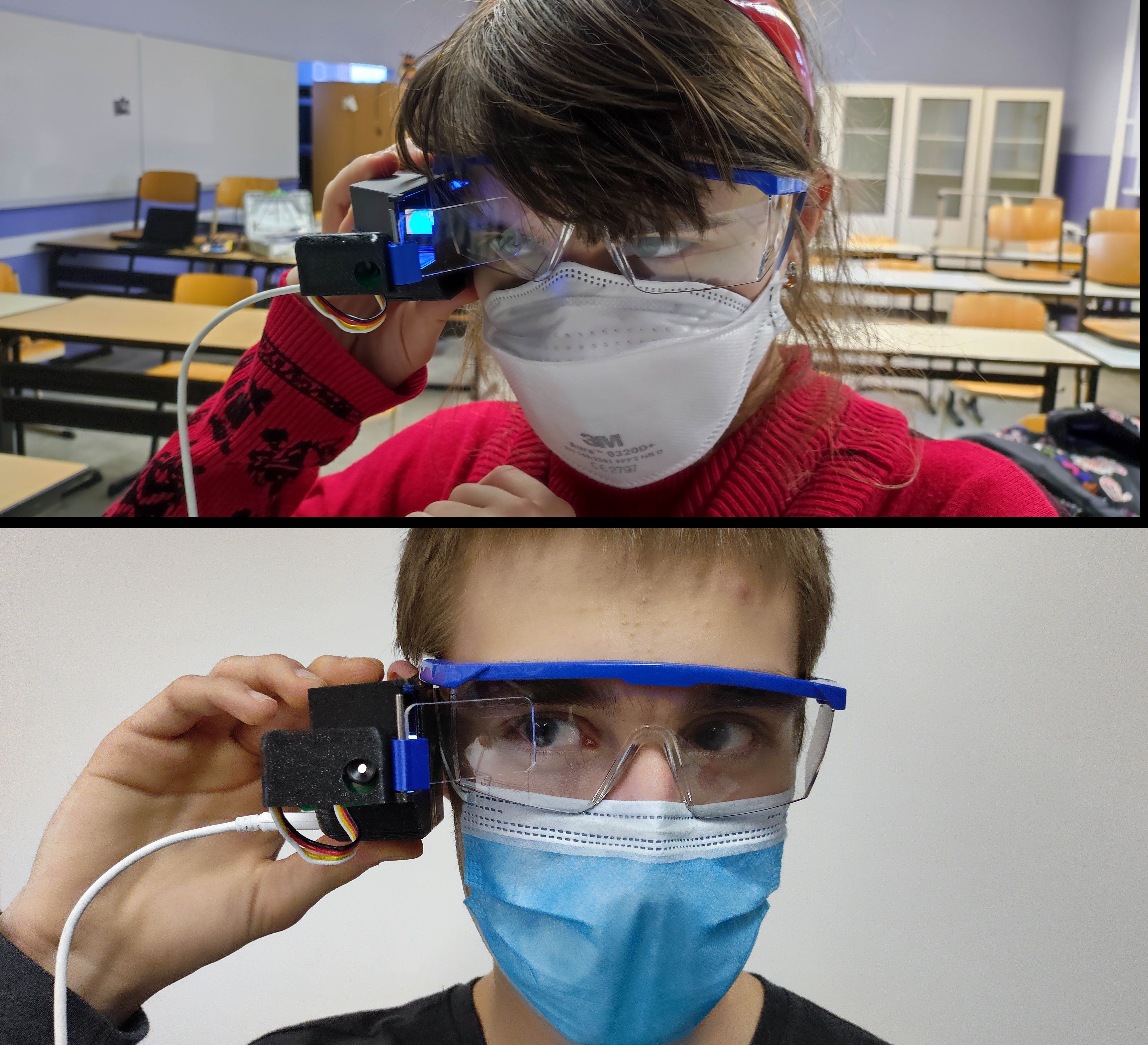
8Final tests, once the AR monocular is attached to the frame of safety glasses
Get yourself safety goggles - they can always be handy :-) and just glue the AR monocular to the frame on your preferred side.
![]()
Then you can easily adjust the transparent screen... and if everything is OK, you can also glue the bottom part to the part holding the sensor and make sure, it does not move inside the case (it slid a bit upwards; the thermal lens is the white spot).
Ready to do some maintenance work in your garden? -
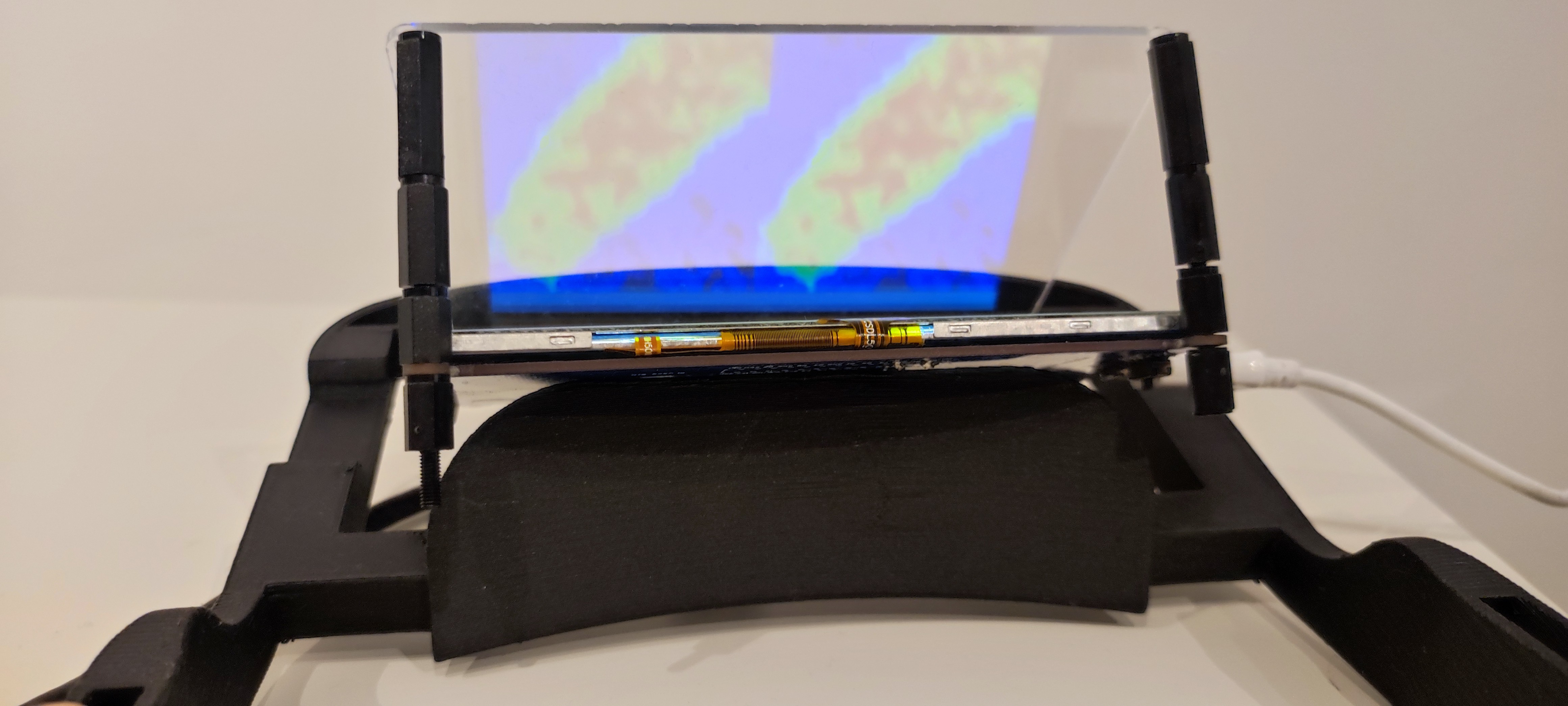
9AR Headset
If you decide for the AR headset, you basically need to do the same steps as above... but use a Raspberry Pi3B at least instead of the Raspberry Pi Zero - the performance would not be good enough (we run a webserver and combine the thermal and visible light image in one prototype to save on Raspberry Pi's and thermal sensors)...+
You just need to 3d-print the linked file from Cults3D for the headset and add the part that holds the bigger transparent screen...
![]()
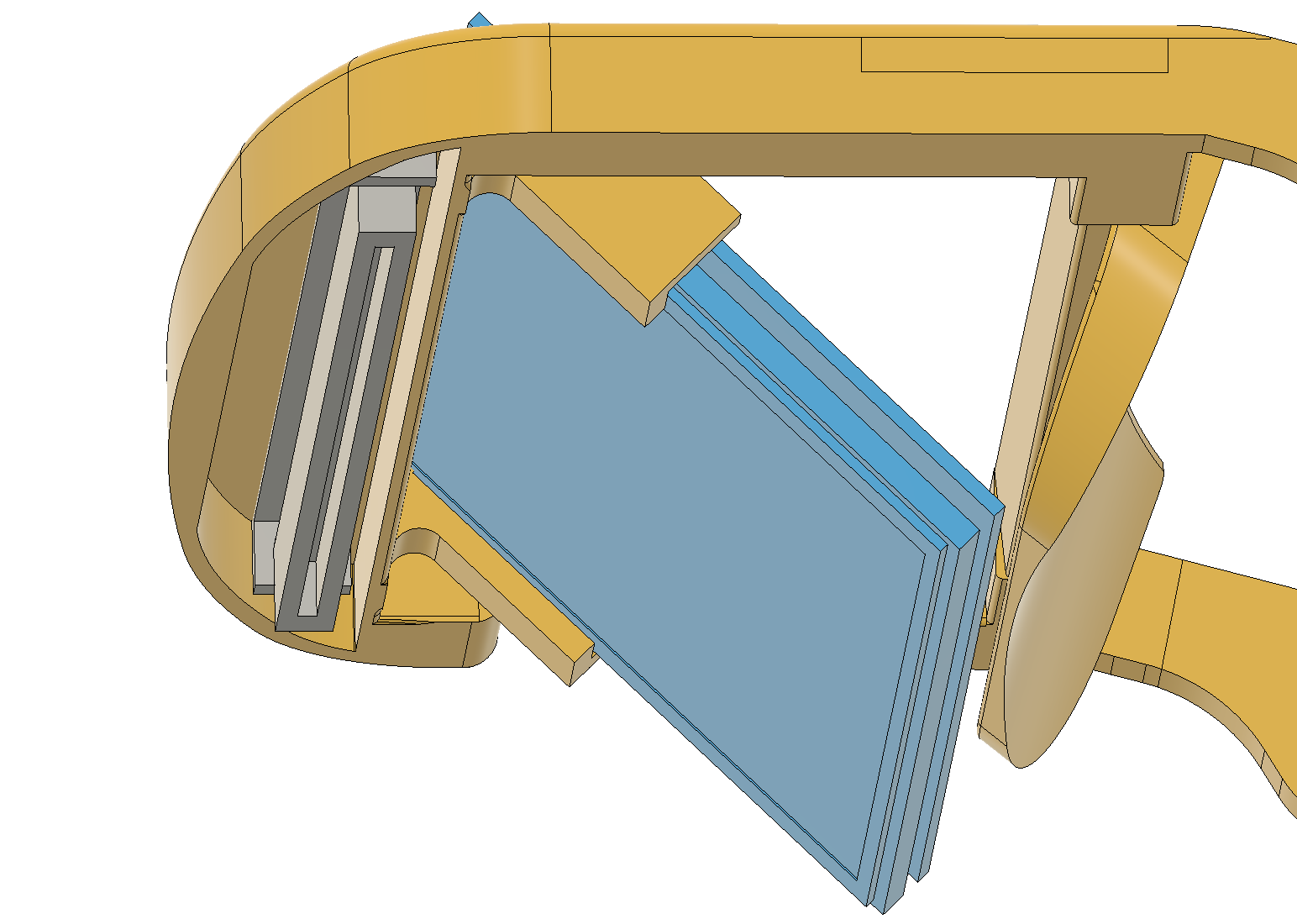
You can of course use some plastic bolts to keep the right distance between the screen and display...
But we didn't like the pointy parts near our eyes for some reason, so we 3d-printed a better holder:
![]()
The grey one... just hot-glued it into place :-)
-
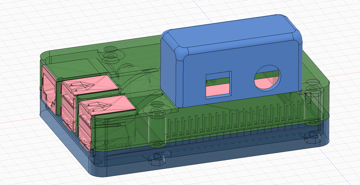
10Raspberry Pi for AR and VR
As explained, we only had enough money for 2 thermal sensors and one of each Raspberry Pis (next to the displays), so we designed a dual-purpose case:
![]()
The easiest way is to use a case for the Raspberry Pi3 like this and add the sensor box:
https://gallery.autodesk.com/projects/118281/simple-pi-case
You can also just go for the thermal vision only and leave the Raspberry Pi cam out (only needed for VR).
Since the setup for the VR version is nearly identical to most of the steps, we decided to leave it out... just solder the MLX 90640 to the DuPont cables and use the Raspberry Pi headers... and attach the camera module. There are many tutorials on how to enable the Raspberry Pi Camera module.
Then all you need is to 3d-print a case like that and have the sensor (in an enclosure with the camera) sitting on top of it. Just fix this to the top of your VR googles, and you are ready to go!
Hedge Watcher
Save breeding songbirds with VR and AR thermal imaging during hedge-trimming work
Discussions
Become a Hackaday.io Member
Create an account to leave a comment. Already have an account? Log In.