 Dan Julio
-
1Gather parts / notes about parts
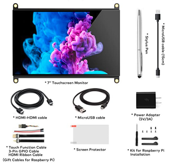
I bought my monitor from Amazon. As I write this it can currently be found at this link. If that link rots then you can search for for "Raspberry Pi Screen,NORSMIC 7 inch Monitor, IPS HD 1024×600, Responsive Capacitive Touch". Here's a picture showing the parts that came with my monitor. You'll be using a couple of them.
![]()
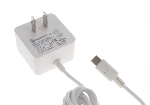
The included Power Adapter will work but due to typical voltage drops in USB cables which will reduce the charge current, you should use a USB Micro-B adapter that puts out 5.1 or 5.25 volts at 3 A. The official Raspberry Pi adapter works well.
![]()
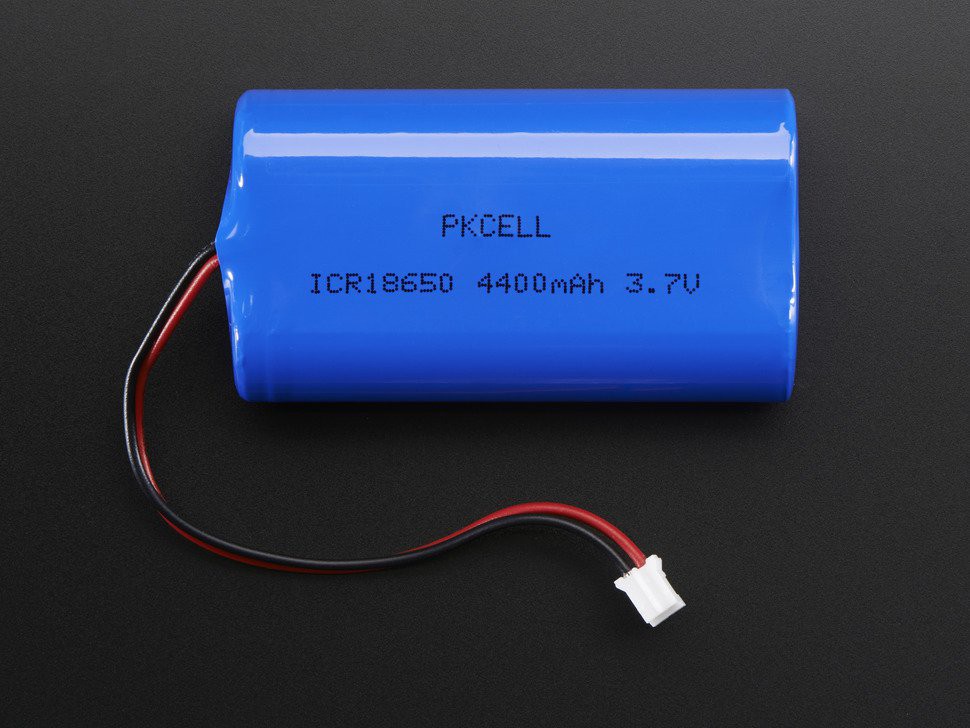
The Pi Platter can provide up to 750 mA charge current for the attached 3.7V LiPo battery. This is a good match for a matched dual-18650 4400 mA pack. I got mine from Adafruit. Be sure it has the Sparkfun/Adafruit JST pinout.
![]()
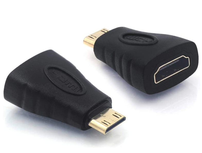
Get the smallest HDMI to HDMI mini adapter you can find. I had an old one that I bought when the first Pi Zero came out but it appears other models are equally as small.
![]()
You'll also need a Raspberry Pi Zero 2 W (or Raspberry Pi Zero W) and a micro SD Card for the Raspberry Pi OS, a Pi Platter, some zip-ties and the ability to 3D print (or otherwise fashion) a simple mounting plate which is described in the next step.
-
2Mount Plate
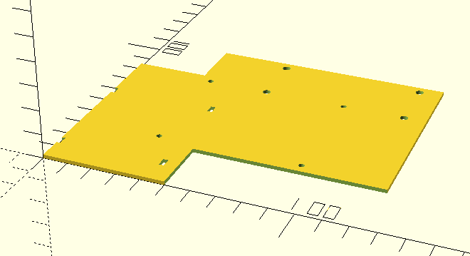
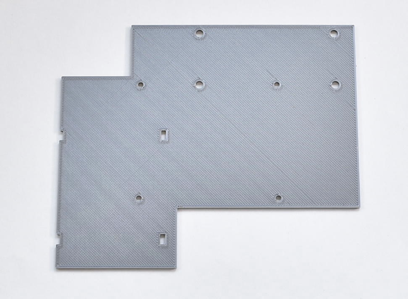
A simple mount plate is used to hold the battery pack. It has holes spaced for the Raspberry Pi mount points on the monitor PCB, holes for the Pi Platter and zip tie cut-outs for the battery. The design is in OpenSCAD and that file, and the generated STL are included in the "mount_plat.zip" file included in this project.
![]()
If you don't have access to a 3D printer you can convert the design for a laser cutter or even drill a very sturdy piece of cardboard with the dimensions (mm) in the OpenSCAD source file.
![]()
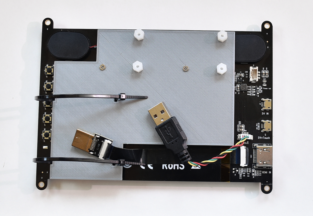
Add a set of four 0.25" M3 standoffs with nuts and zip ties for the battery. The zip ties should be loose enough for the battery to be installed. They can be tightened then.
-
3Prepare the monitor
The monitor comes with a bunch of useful cables. The build uses 2 of them.
- HDMI plug with flex cable
- USB Type A plug with wire harness to 4-pin connector
The USB Type A to USB Micro-B can also be used with a power adapter to power/charge the system.
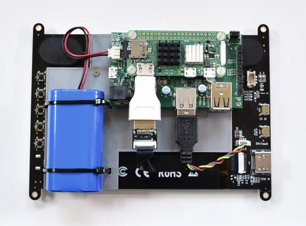
Connect the flex and USB cables as shown below. The flex cable has double sticky tape on one side. I also used another piece of tape to make sure the connection was secure.
![]()
Attach the mount plate to the Raspberry Pi standoffs on the monitor using screws supplied with the monitor.
![]()
-
4Mount the Pi Platter and Pi Zero
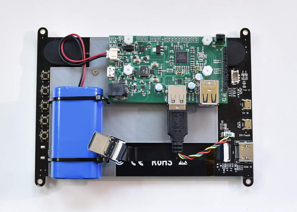
Mount the Pi Platter using another four 0.25" nylon standoffs . Insert the battery and tighten the zip ties. Connect it to the Pi Platter.
![]()
Plug the monitor into the single (unswitched) USB connector on the Pi Platter. This controls the monitor's capacitive touchscreen (which is automatically supported by Pi OS).
Mount the Pi Zero onto the Pi platter using four nylon screws. Plug the HDMI cable into the HDMI to Mini HDMI adapter and plug that into the Pi.
![]()
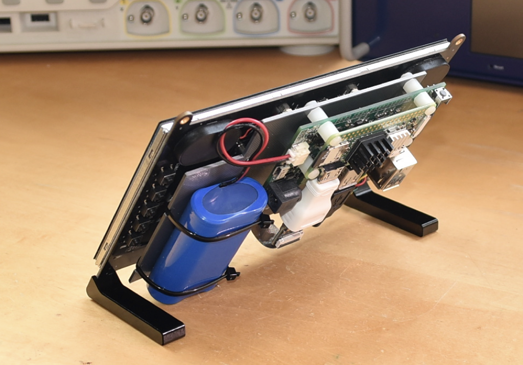
Finally you can add the angled feet included with the monitor.
![]()
Congratulations! The basic hardware is assembled.
-
5Install Pi Platter software
The Pi Platter has software support that enables sophisticated power management. Please see the github repository for source and compiled 32-bit binaries for installation on Raspberry Pi OS as well as installation instructions.
Auto shutdown on critical battery voltage
The Pi Platter will automatically shut down power when the battery reaches a critical voltage. The ppd daemon running on the Pi can initiate a controlled OS shutdown before this occurs.
Auto power off after software shutdown initiated
The ppd daemon can also switch system power off when it detects a SIGTERM signal which is sent when a software shutdown is initiated on the Pi (for example with the shutdown command or by selecting shutdown from the GUI menu).
GUI monitoring of battery status and USB port power control
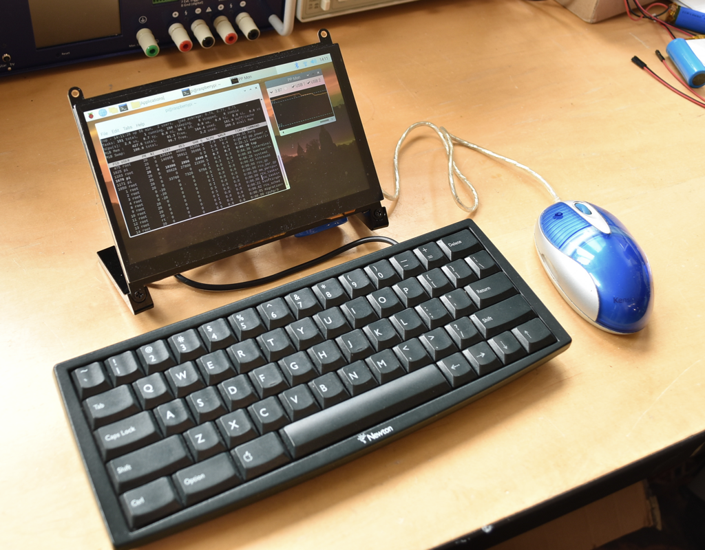
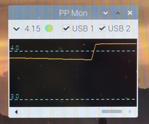
The pp_power_mon application displays the battery voltage (with optional graph) and provides control of the two switched USB ports on the Pi Platter.
![]()
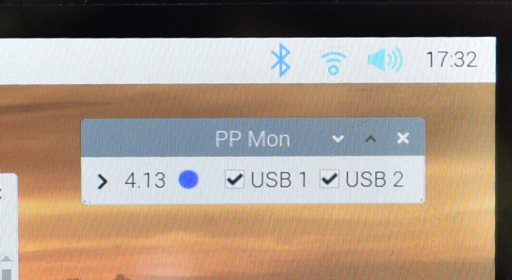
The application displays a blue indicator when running on battery power. The indicator turns yellow then red as the battery is depleted.
![]()
Clicking the disclose triangle shows the battery discharge graph. The indicator turns green when the system is powered by the power supply connected to the Pi Platter power USB input port and the battery is charging.
![]()
Porta-Pi - A portable large-screen Pi Zero 2 W rig
Combining the Raspberry Pi Zero 2 W, a Pi Platter expansion board and a 1024x600 pixel HDMI touchscreen in an easy-to-build portable.

Discussions
Become a Hackaday.io Member
Create an account to leave a comment. Already have an account? Log In.