To make the experience fit your profile, pick a username and tell us what interests you.
We found and based on your interests.
After final assembly of the Reflow Oven, I knew I need to test and tune the PID parameters.
The sample ARDUINO program provided by ROCKET SCREAM uses a few ARDUINO libraries; most notable are Brett Beauregard’s PID and Limor Fried’s (LadyAda) MAX6675 libraries. The PID library can be found here and the MAX6675 library can be found here. The ROCKET SCREAM Reflow Oven Controller Shield schematics, PCB artworks and sample sketch can be found here.
Disclaimer: My interaction with the code and libraries was from mid-2012. The code and libraries may have been updated since that time. I will only describe my experiences from notes journaled from that time. Also, I am not an expert at PID nor reflow ovens.
Initial testing: I started by running the ROCKET SCREAM sample sketch, which uses the PID library. The sample sketch uses three sets of PID parameters; “preheat”, “soak” and “reflow”. The sample sketch uses SW1 to start the cycle. In addition to info printed on the LCD, the sample sketch emits a string of technical info out the serial port, presumably to capture and analyze a flow-curve. I created a spreadsheet and graphed the data with time (X-axis) vs. Temp (Y-axis) vs. Slope (2nd Y-axis).
With the default PID values I had overshoot by 20 deg C from preheat (150°C) to soak (155°C) in my oven and 10 deg C overshoot from “soak” to “reflow” (230°C). The ROCKET SCREAM code switches to cool once the temperature reaches “reflow” minus 5 degrees. Obviously it needed some tuning.
Modifying the PID parameters and testing each time means re-compiling and uploading to the ARDUINO over and over, which quickly becomes time consuming.
Brett Beauregard has made a GUI front-end to control an ARDUINO running his PID routines in real-time. It is for manual tuning, NOT auto-tuning. If you need to tune, get this GUI front-end. With it, you can tweak the PID parameters and send them to the ARDUINO for monitoring the effects in real-time. Since Brett’s sample ARDUINO code uses “analog(0)” for input and outputs a PWM signal with an “analogwrite”, I had to modify the input to use the MAX6675 and the output to drive an SSR in “virtual PWM” mode. For that, I borrowed the code from ROCKET SCREAM’s sketch that made that same conversion to Brett’s original sample PID code. Brett discusses this in his BLOG. I thought that updating the LCD would be good too.
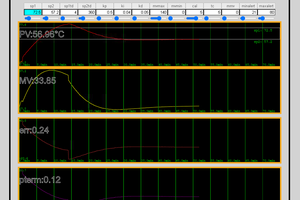
With Bret’s GUI, I found a few issues; the host sketch (running under process from process.org) wanted to access the 2nd COM port on my computer, which at the time was running WINDOWS 7®. The TOSHIBA Bluetooth Stack wanted to name “COM65” and the ARDUINO IDE was using COM2. The line near 100 in Brett’s GUI is “myPort = new Serial(this, Serial.list()[1], 57600);”, change the “[1]” to whatever port you need that shows up on the bottom of the sketch message box. Also, I found that in order to reliably connect with the ARDUINO, the ARDUINO should be held in reset until the GUI front-end comes up then release the reset. I also found a bug that disables accessing any of the controls in the GUI but I don’t know what causes it. To remedy, kill the GUI and restart it. This GUI sure has helped to save a lot of time setting the PID parameters for the “preheat” stage! Below is an example of the performance of one of my first attempts at tuning. Notice the overshoot and low frequency oscillation around the set-point while the PID algorithm tries to compensate and stabilize. Eventually, with the correct PID parameters, I was able to minimize the overshoot and improve the stabilization.
Brett has also released an auto-tune routine. Though at the time, he did not post any docs or helpful info to get it up and running. After studying the code and making some mods, I found that first the oven must...
Read more »In my last post, I listed the components needed to build a reflow-oven and the components I chose for my design.
In this post, I will outline the steps I used to build my reflow-oven along with some photos.
As mention, I am using a BLACK & DECKER Model TRO355. In order to make room inside for the SSR and because it was no longer needed, I had to remove the temperature controls. There were some pre-stamped holes in the back and bottom of the metal housing of the oven. I used one of them to feed the thermocouple through and used Aluminum Foil Tape to seal the hole and secure the wires along the back side.
Referring to the photos above, in the left photo, the thermocouple can be seen “hanging down” as it needs to be near the PCB’s. In the middle and right photos, the SSR is mounted at the bottom-front of the compartment. The black Bakelite “block” with the leaf-springs is the door-disconnect safety switch, which I left in place as a precaution since it immediately cuts power to the heating elements when the door is opened. I also had to bypass the temperature control using 10 gauge single-strand wire but the method cannot be readily seen in the photos.
Referring to the photos above; the individual modules that make up the PID controller needed to fit in a plastic enclosure.
The LCD was not a direct-connection to the ROCKET SCREAM PID controller shield, so a connector had to be fitted (left photo). Also, the LCD had a flex-strip for its interface cable, so I had to directly solder individual 30 gauge KYNAR wires to the flex connector then crimp the other ends into an IDC connector to mate to the LCD connector on the PID controller shield.
I used a CP2102-based USB-to-Serial bridge to interface with the AVR-based “Mini-Ultra” module. The USB-to-Serial bridge comes with a USB “type-A” connector, which I removed. I wanted to use a USB “Mini-B” connection instead, so I needed to fashion a daughter-board to mate it with that also supply 5 volts from the USB bus (middle and right photos).
The reflow controller shield came with an 8×2 LCD, 3 on-board switches (w/ hardware debounce circuitry) for “RESET”, “SW1” and “SW2”, two LEDS and a beeper. There is also a 6-position mini-terminal block for the thermocouple, Heat SSR and (cooling) Fan SSR connections. The included LCD detaches and a “standard” 16 pin (2×8) LCD header is available to “extend” the LCD somewhere else. I planned to use the 16×2 LCD, so having the LCD connector available was the best option.
The only issues I had with the design layout of the reflow controller shield was that if one wants to use external switches through the reflow controller shield (like me), then there is no way to attach them in parallel to those on-board. Nor is there any way to attached external LEDs for front panel display. So that required a little bit of hacking by soldering the external switch and LED wires directly to to the reflow controller shield.
Referring to the photos above; a 6 x 3 x 2 inch project box was used but it needed some holes cut into before the components could be mounted. I needed a rectangular cutout for both the LCD (middle-left photo) and the USB Min-B connector access (middle-right photo).
After assembling the “Mini-Ultra” PCB and leaving the 3.3V regulator off, I was able to hard-solder the D13:0 pins of the “Mini-Ultra” right to the reflow controller shield’s D13:0 pins and stretch some connect wires for power, ground, reset,...
Read more »The foundational base for this project required some sort of oven. From the design perspective, I needed an oven, preferably one with a good heat-up slope, a temperature sensor, a solid-state relay that was capable of handling “house-hold” voltage and at least 20 amps of current and a PID controller.
Oven selection: There are plenty of “toaster ovens” manufactured by various manufacturers available all around the world. The oven must be able to attain and sustain at least 230°C, which is about 450°F. However, in testing some of the ones I had access to, they had a poor heat-up slope. For use as a reflow-oven, a slope of 1°C to 2°C is adequate but an oven that can attain and sustain 260°C (500°F) is needed. The higher the heat-up slope, the better. On oven with four heating elements is best; two on the top and two on the bottom is great because it increases the heat-up slope. Also, a small interior is best as the models with the larger interior take too much time to heat up and had a low heat-up slope.
I happened to have a relative that decided she wanted to upgrade from her “dinky” toaster oven to one a bit larger. Perhaps one that could fit a pre-made 12 inch pizza? She “gifted” her old one to me, which was like new. I mean, it looked like it had never been used and perhaps it never had. It was a BLACK & DECKER Model TRO355. It boasted 1550 watts of power usage, which translated to good heat generation capability. In testing, I found that it performed with a heat-slope of on average, 1.5°C per second. It has 4 heating elements, top and bottom and a small cavity. In testing, it was able to attain and sustain about 275°C (525°F). Perfect for my use.
PID controller: The PID controller is the most important piece of the reflow-oven because it has to accurately detect the temperature and constantly adjust it to maintain the desired solder profile. The PID controller has to take into account the rather slow response of a heating and regulating the heat in the target environment. It has to “source” heat into the environment and effectively monitor the environment’s ability to “sink” (cool) heat out of it, accurately regulating it all the while to maintain a stable temperature within said environment. PID controllers are heavily used in chemical and industrial manufacturing processes. As a matter of fact, there has been much information published about how the PID (Proportional-Integral-Derivative) algorithms work and how to calibrate a PID controller for any particular application, which for an industrial application, can sometimes take hours, days or even weeks to stabilize.
In my research, I looked into several low-cost “stand-alone”PID controllers but they were intended to regulate a single temperate with only one “set point”, perhaps two. I needed one that was adjustable and programmable, so I gave up on that type. With that avenue being a dead-end, I started looking into what I would need if I wanted to build my own. As I stated earlier, there were a few sources available on the Internet. Mostly college students that were designing reflow-ovens for their semester-end projects and for use in the college lab.
I did find a unit by TechFX that seemed to have everything I needed and was based on a PIC processor. The PCB was fairly inexpensive, about US$25. In testing with my B&D oven, I found that it was not stable and did not perform well. A suggested firmware update by the OEM didn’t help either. At the time, I was romantically involved with a female applications engineer who had worked in the pharmaceutical industry designing and maintaining process controls. She used to work for two of the leading high-end industrial PID controller OEM’s. While employed for one of them, she wrote a technical brief detailing...
Read more »This project was started and finished a few years ago. One can find some projects on the Internet that are similar but I decided that I would post this project for those that are in the process of determining if they wish to create their own and what would be needed to do so.
My need arose when I embarked on a project that is essentially the “big brother” to the ATtiny12L Frequency Generator project that I had worked on many years ago. In this particular project, the goal was to produce a frequency generator that was small and portable, meaning efficiently battery powered and easy to use. During my component selection, I was faced with the fact that in order to meet the “small and portable” criteria, I had to use SMT devices. Many of those devices simply were not available in a through-hole package. Some of the devices were 3×3 mm DFN and QFN packages. My expected quantities did not justify the expense of a contract manufacturing facility, so I would need to populate and produce these devices on my own. The ONLY solution was to be my own “pick and place” machine and to acquire a reflow-oven. Anyone who has looked into a reflow-oven can attest to the fact that even the least expensive version can be in the 1000’s of dollars (US). Thus, I set out to researching just what were my options in building one on my own.
Create an account to leave a comment. Already have an account? Log In.
I replaced the cross bars on the shelf (they just snapped off with a little twisting) with a mesh like this:
http://www.diy.com/departments/aluminium-panel-l500mm-w500mm-t1mm/254124_BQ.prd
it stopped my boards from having an un even temperature profile because of the added thermal inertia of the bars.
Hi Lee:
Thanks for the comment. The mesh is a great idea.
I found in my oven that the longer "soak" period helped with that. Perhaps its that my oven has a smaller cavity than others and there is little temperature differential. I suppose I should add that in my oven, the lower two elements are vertically stacked, whereas the upper elements are spaced horizontally across the top. When the oven was on, there was an intense heat flowing upward off the lower elements (directly at my PCB's) and that is one reason why I am using the baking pan, to deflect that heat around the pan and away from my boards, thereby allowing the pan to "sink" the intense heat from the lower elements. The broiling rack puts an "insulation layer" between the pan and my boards. On one of the PCB's, I have a SMT thermistor located on the back, which also gets reflow soldered. If I had a PCB with a high part density on both sides, I guess I would have to make some sort of support legs and not use the rack. I can't speak for any one else's specific oven but this is what has worked fairly well for me.
As I said, the mesh looks like a good idea. Do you reflow any PCB's with parts on both sides? If so, how do you keep the parts on the back side from being disrupted by the mesh?
Lee, thank you again for your comment.
Peace and blessings,
Johhny
Just a thought -- I did a similar mod a few years ago and ended up moving to a stock convection toaster oven. Non-convection toaster ovens (at least in my experience) tend to have issues with temperature consistency, meaning a board may overheat in one spot while still reflowing in another.
Having said that, no need to mess with something that works for your needs!
Hello "zakqwy":
Thank you for the comment. I have thought about that, using a convection oven, but it really is a fairly small space and the heat distribution SEEMS to be good. At the time, I had considered adding a fan on the top of the unit to blow air inside of the heating space. I gutted the fan out of a non-functioning "Flavor-wave" oven. The fan was inside the "Flavor-wave" oven circulating the air, so it was designed for that purpose and it could take the heat. I couldn't figure out how to mount it effectively so I did not use it.
I've reflow-soldered at least 30 various sized PCB's in it since, sometimes 2 or 3 at a time and the solder connections always looked pretty good.
Since it has no cooling fan to reduce the temperature after the peak of the reflow, I have to babysit it and open the door once the reflow cycle ends and let it cool down on its own.
Peace and blessings,
Johnny
Putting it all together - https://smdreflowoven.wordpress.com/2016/12/05/putting-it-all-together/
Component research and selection - https://smdreflowoven.wordpress.com/2016/12/05/component-research-and-selection/
A home-brew SMT Reflow Oven - https://smdreflowoven.wordpress.com/2016/12/05/a-home-brew-smt-reflow-oven/
Become a member to follow this project and never miss any updates

 Coders' Cafe
 W5FCX
W5FCX
 Michael Ratcliffe
 justin.richards
Reflow-oven controller PID and performance tuning - https://smdreflowoven.wordpress.com/2016/12/06/reflow-oven-controller-pid-and-performance-tuning/