 Scott
Scott-
Reflow-oven controller PID and performance tuning
02/06/2017 at 08:44 • 0 commentsAfter final assembly of the Reflow Oven, I knew I need to test and tune the PID parameters.
The sample ARDUINO program provided by ROCKET SCREAM uses a few ARDUINO libraries; most notable are Brett Beauregard’s PID and Limor Fried’s (LadyAda) MAX6675 libraries. The PID library can be found here and the MAX6675 library can be found here. The ROCKET SCREAM Reflow Oven Controller Shield schematics, PCB artworks and sample sketch can be found here.
Disclaimer: My interaction with the code and libraries was from mid-2012. The code and libraries may have been updated since that time. I will only describe my experiences from notes journaled from that time. Also, I am not an expert at PID nor reflow ovens.
Initial testing: I started by running the ROCKET SCREAM sample sketch, which uses the PID library. The sample sketch uses three sets of PID parameters; “preheat”, “soak” and “reflow”. The sample sketch uses SW1 to start the cycle. In addition to info printed on the LCD, the sample sketch emits a string of technical info out the serial port, presumably to capture and analyze a flow-curve. I created a spreadsheet and graphed the data with time (X-axis) vs. Temp (Y-axis) vs. Slope (2nd Y-axis).
With the default PID values I had overshoot by 20 deg C from preheat (150°C) to soak (155°C) in my oven and 10 deg C overshoot from “soak” to “reflow” (230°C). The ROCKET SCREAM code switches to cool once the temperature reaches “reflow” minus 5 degrees. Obviously it needed some tuning.
Modifying the PID parameters and testing each time means re-compiling and uploading to the ARDUINO over and over, which quickly becomes time consuming.
Brett Beauregard has made a GUI front-end to control an ARDUINO running his PID routines in real-time. It is for manual tuning, NOT auto-tuning. If you need to tune, get this GUI front-end. With it, you can tweak the PID parameters and send them to the ARDUINO for monitoring the effects in real-time. Since Brett’s sample ARDUINO code uses “analog(0)” for input and outputs a PWM signal with an “analogwrite”, I had to modify the input to use the MAX6675 and the output to drive an SSR in “virtual PWM” mode. For that, I borrowed the code from ROCKET SCREAM’s sketch that made that same conversion to Brett’s original sample PID code. Brett discusses this in his BLOG. I thought that updating the LCD would be good too.
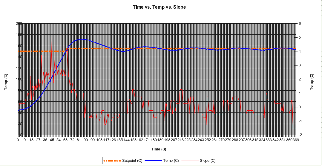
With Bret’s GUI, I found a few issues; the host sketch (running under process from process.org) wanted to access the 2nd COM port on my computer, which at the time was running WINDOWS 7®. The TOSHIBA Bluetooth Stack wanted to name “COM65” and the ARDUINO IDE was using COM2. The line near 100 in Brett’s GUI is “myPort = new Serial(this, Serial.list()[1], 57600);”, change the “[1]” to whatever port you need that shows up on the bottom of the sketch message box. Also, I found that in order to reliably connect with the ARDUINO, the ARDUINO should be held in reset until the GUI front-end comes up then release the reset. I also found a bug that disables accessing any of the controls in the GUI but I don’t know what causes it. To remedy, kill the GUI and restart it. This GUI sure has helped to save a lot of time setting the PID parameters for the “preheat” stage! Below is an example of the performance of one of my first attempts at tuning. Notice the overshoot and low frequency oscillation around the set-point while the PID algorithm tries to compensate and stabilize. Eventually, with the correct PID parameters, I was able to minimize the overshoot and improve the stabilization.
![screenshot-150c_stabilize]() Tuning the “soak” stage
Tuning the “soak” stageBrett has also released an auto-tune routine. Though at the time, he did not post any docs or helpful info to get it up and running. After studying the code and making some mods, I found that first the oven must already be stabilized, then the auto-tune routines can be used. As it turns out, these routines will not help with automatically tuning the PID parameters for any particular oven. So no “press a button and auto PID for my oven majick”. I found no need to implement it in the ROCKETSCREAM code.
As shown below, with a little tuning, the results look more satisfactory.
![screenshot-better_pid]() Better results after tuning
Better results after tuningThe final outcome of my PID parameters for “pre-heat“, “soak” and “reflow” is depicted below. Notice that my oven is capable of achieving a 2°C to 2.5°C per second heat-slope. As I stated, a heat-slope at or below 1°C per second is sufficient for the “soak” stage but insufficient for the “reflow” stage. 1.5°C per second or better is required.
![screenshot-p100i0p25d025]() Performance of complete “pre-heat”, “soak” and “reflow” stages
Performance of complete “pre-heat”, “soak” and “reflow” stagesIn my oven, I use the oven’s provided aluminum tray and broiling rack to hold my boards. These items are heat-sinks and need a little more time to absorb the heat, thus I have extended my “soak” stage to be 240 seconds, which seems to yield acceptable results for my applications. I had thought about adding a fan to circulate the heat within the oven chamber but was unable to figure out a means to attach it and not interfere with any of the pre-existing internals of the oven; rack and heating elements. Also, I made the temperature setting for “pre-heat” and “soak” the same because I saw no need for a “pre-heat” stage as it did not get me anything extra. Although, I can see that using PID in process control on a larger scale may benefit from a “pre-heat” stage.
Words of experience: Since I am no expert on PID, process controls nor reflow ovens, I cannot offer any (free) “expert advise” as I have none to give. However, I can share my experiences, which are journaled within these pages.
The bottom line on setting the PID parameters for use with the ROCKET SCREAM sketch and a small-scale home-brew reflow oven is to use trial and error. In all, it probably took me a dozen or so hours to try different settings, capture the results, graph them and use them to adjust new settings. I started with P, I and D set to “0” just to see what the “raw” results would be without having any adjustments made. Then I started to adjust the P setting and test that. From my experiences, the ambient temperature also had an effect on the results. I have seen some home-brew designs that use a “thermal blanket” wrapped around the oven to insulate it from ambient temperature effects and to keep the heat within the oven cavity but I saw no need for that in my small oven. From what I recall, the “thermal blanket” material is also rather expensive.
I consulted some PID tuning reference material available on-line and here are a few reference links from my project journal to get started:
- Bret Beauregard’s PID library blog
- http://straightlinecontrol.com/
- http://expertune.com/tutor.aspx
- http://csimn.com/CSI_pages/PIDforDummies.html
- PID without a Ph.D – Wescott (PDF)
- PID without Math – Lacoste (PDF)
- Tuning of PID Controllers – author(s) unknown (PDF)
- Design and Construction of a Reflow Soldering Oven – Gebre, Johnson, Russell and Sun (PDF)
-
Putting it all together
02/06/2017 at 08:43 • 0 commentsIn my last post, I listed the components needed to build a reflow-oven and the components I chose for my design.
In this post, I will outline the steps I used to build my reflow-oven along with some photos.
As mention, I am using a BLACK & DECKER Model TRO355. In order to make room inside for the SSR and because it was no longer needed, I had to remove the temperature controls. There were some pre-stamped holes in the back and bottom of the metal housing of the oven. I used one of them to feed the thermocouple through and used Aluminum Foil Tape to seal the hole and secure the wires along the back side.
![Nice oven! No controls!]() Nice oven! No controls!
Nice oven! No controls!
Side open, dials removed, controls bypassed and SSR in place![Side open, dials removed, controls bypassed and SSR in place]()
Closer view of the compartment![Closer view of the compartment]()
Referring to the photos above, in the left photo, the thermocouple can be seen “hanging down” as it needs to be near the PCB’s. In the middle and right photos, the SSR is mounted at the bottom-front of the compartment. The black Bakelite “block” with the leaf-springs is the door-disconnect safety switch, which I left in place as a precaution since it immediately cuts power to the heating elements when the door is opened. I also had to bypass the temperature control using 10 gauge single-strand wire but the method cannot be readily seen in the photos.
![Back of LCD with custom cable mod]() Back of LCD with custom cable mod
Back of LCD with custom cable mod
CP2103-based USB-2-Serial Bridge![CP2103-based USB-2-Serial Bridge]()
CP2103-based USB-2-Serial Bridge![CP2103-based USB-2-Serial Bridge]()
Referring to the photos above; the individual modules that make up the PID controller needed to fit in a plastic enclosure.
The LCD was not a direct-connection to the ROCKET SCREAM PID controller shield, so a connector had to be fitted (left photo). Also, the LCD had a flex-strip for its interface cable, so I had to directly solder individual 30 gauge KYNAR wires to the flex connector then crimp the other ends into an IDC connector to mate to the LCD connector on the PID controller shield.
I used a CP2102-based USB-to-Serial bridge to interface with the AVR-based “Mini-Ultra” module. The USB-to-Serial bridge comes with a USB “type-A” connector, which I removed. I wanted to use a USB “Mini-B” connection instead, so I needed to fashion a daughter-board to mate it with that also supply 5 volts from the USB bus (middle and right photos).
The reflow controller shield came with an 8×2 LCD, 3 on-board switches (w/ hardware debounce circuitry) for “RESET”, “SW1” and “SW2”, two LEDS and a beeper. There is also a 6-position mini-terminal block for the thermocouple, Heat SSR and (cooling) Fan SSR connections. The included LCD detaches and a “standard” 16 pin (2×8) LCD header is available to “extend” the LCD somewhere else. I planned to use the 16×2 LCD, so having the LCD connector available was the best option.
The only issues I had with the design layout of the reflow controller shield was that if one wants to use external switches through the reflow controller shield (like me), then there is no way to attach them in parallel to those on-board. Nor is there any way to attached external LEDs for front panel display. So that required a little bit of hacking by soldering the external switch and LED wires directly to to the reflow controller shield.
!["Mini-Ultra" and PID controller shield; mates for life!]() “Mini-Ultra” and PID controller shield; mates for life!
“Mini-Ultra” and PID controller shield; mates for life!
LCD and Pushbuttons![LCD and Pushbuttons]()
USB Mini-B and hole for SSR and Thermocouple wires![USB Mini-B and hole for SSR and Thermocouple wires]()
All modules mounted in the enclosure![All modules mounted in the enclosure]()
Referring to the photos above; a 6 x 3 x 2 inch project box was used but it needed some holes cut into before the components could be mounted. I needed a rectangular cutout for both the LCD (middle-left photo) and the USB Min-B connector access (middle-right photo).
After assembling the “Mini-Ultra” PCB and leaving the 3.3V regulator off, I was able to hard-solder the D13:0 pins of the “Mini-Ultra” right to the reflow controller shield’s D13:0 pins and stretch some connect wires for power, ground, reset, etc. Thus the “Mini-Ultra” and PID controller shield were “mated” together with a minimum of effort and holes were drilled in the enclosure for mounting them (left photo). All modules and components fit into the enclosure with some room to spare (right photo).
![Enclosure mounted to side of oven]() Enclosure mounted to side of oven
Enclosure mounted to side of oven
Enclosure mounted to side of oven![Enclosure mounted to side of oven]()
Referring to the photos above; the oven was reassembled with the thermocouple and SSR wires routed outside the oven “control compartment” and the enclosure was mounted to the side of the oven. The themocouple and SSR wires were threaded into the enclosure and fastened to their respective terminal block connections on the PID controller shield.
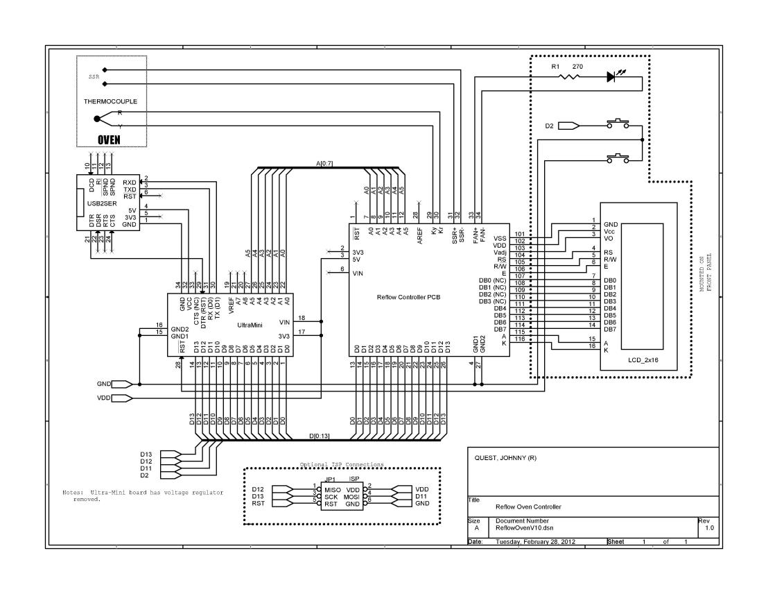
The schematic for the module and component interconnections is below. A full-sized JPEG schematic is here.
![reflowovenv10]() Module Interconnections
Module InterconnectionsThe modified ARDUINO sketch is posted below.
/******************************************************************************* Title: Reflow Oven Controller Version: 1.31 Date: 2016-0618 Company: Rocket Scream Electronics Website: http://www.rocketscream.com ============================================================================== Additional modifications: (2012) Johnny Quest (ksv_prj [at] gmx [dot] com ============================================================================== Revision Description ======== =========== 1.31 JQ – Moved message strings to PROGMEM, which was not really necessary. Uses: “Arduino Pro Mini” w/ Mega328p @8MHz 1.30JQ – Forgot what I did!. 1.20JQ – Added support for 16×2 “external display”. Added support for displaying real-time temperature slope Added support for remaining “soak time” Added support for elapsed time at “wet zone” temperature 1.10 Arduino IDE 1.0 compatible. 1.00 Initial public release. ******************************************************************************** Brief ===== This is an example firmware for our Arduino compatible reflow oven controller. The reflow curve used in this firmware is meant for lead-free profile (it’s even easier for leaded process!). Please check our wiki (www.rocketscream.com/wiki) for more information on using this piece of code together with the reflow oven controller. Temperature (Degree Celcius) Magic Happens Here! 245-| x x | x x | x x | x x 200-| x x | x | | x | x | | x | x | | 150-| x | | | x | | | | x | | | | x | | | | x | | | | x | | | | x | | | 30 -| x | | | |< 60 – 90 s >|< 90 – 120 s >|< 90 – 120 s >| | Preheat Stage | Soaking Stage | Reflow Stage | Cool 0 |_ _ _ _ _ _ _ _|_ _ _ _ _ _ _ _ _ _|_ _ _ _ _ _ _ _ _ _ _ _ _ _ _ _ _ _ Time (Seconds) This firmware owed very much on the works of other talented individuals as follows: ========================================== Brett Beauregard (www.brettbeauregard.com) ========================================== Author of Arduino PID library. On top of providing industry standard PID implementation, he gave a lot of help in making this reflow oven controller possible using his awesome library. ========================================== Limor Fried of Adafruit (www.adafruit.com) ========================================== Author of Arduino MAX6675 library. Adafruit has been the source of tonnes of tutorials, examples, and libraries for everyone to learn. Disclaimer ========== Dealing with high voltage is a very dangerous act! Please make sure you know what you are dealing with and have proper knowledge before hand. Your use of any information or materials on this reflow oven controller is entirely at your own risk, for which we shall not be liable. Licences ======== This reflow oven controller hardware and firmware are released under the Creative Commons Share Alike v3.0 license http://creativecommons.org/licenses/by-sa/3.0/ You are free to take this piece of code, use it and modify it. All we ask is attribution including the supporting libraries used in this firmware. *******************************************************************************/ // ***** INCLUDES ***** #include #include #include <avr/pgmspace.h> #include #include #define TEST 0 // set to “1” to enable test code/constants #define DEBUG 0 // set to “1” to enable debug via Serial // ***** TYPE DEFINITIONS ***** typedef enum REFLOW_STATE { REFLOW_STATE_IDLE, REFLOW_STATE_PREHEAT, REFLOW_STATE_SOAK, REFLOW_STATE_REFLOW, REFLOW_STATE_COOL, REFLOW_STATE_COMPLETE, REFLOW_STATE_ERROR, REFLOW_STATE_TUNE } reflowState_t; typedef enum REFLOW_STATUS { REFLOW_STATUS_OFF, REFLOW_STATUS_ON } reflowStatus_t; typedef enum DEBOUNCE_STATE { DEBOUNCE_STATE_IDLE, DEBOUNCE_STATE_CHECK, DEBOUNCE_STATE_RELEASE } debounceState_t; // ***** CONSTANTS ***** // set “1” if LCD has “degree” character, else “0” #define HAS_DEGREE 0 // set “1” if LCD has “delta” character, else “0” #define HAS_DELTA 0 // This is the temperature at which the “complete” signals at #if !TEST #define TEMPERATURE_ROOM 50 #else #define TEMPERATURE_ROOM 80 #endif #define TEMPERATURE_SOAK_MIN 150 #define TEMPERATURE_SOAK_MAX 155 #define SOAK_TEMPERATURE_STEP 5 #if !TEST #define SOAK_MICRO_PERIOD 240000 // 4 minutes (240 seconds) to soak #else #define SOAK_MICRO_PERIOD 300000 // 5 minutes to soak #endif #define TEMPERATURE_REFLOW_MIN 180 // spec’d wet region start #define TEMPERATURE_REFLOW_MAX 230 #if !TEST #define TEMPERATURE_COOL_MIN 60 #else #define TEMPERATURE_COOL_MIN 80 #endif // soak-to-reflow beeper “on” duration in mS #define BEEPDURATION_REFLOW 250 // reflow-to-cool beeper “on” duration in mS #define BEEPDURATION_COOL 2000 // cool-to-complete beeper “on” duration in mS #define BEEPDURATION_COMPLETE 3000 #define DEBOUNCE_PERIOD_MIN 50 #define THERMOCOUPLE_DISCONNECTED 10000 #define SENSOR_SAMPLING_TIME 1000 #define PID_SAMPLE_TIME 1000 // Define PWM @ 100% window size in mS // Note: 2000mS appears to be a crucial value #if !TEST #define PWMWINDOW 2000 #else #define PWMWINDOW 2500 #endif // ******************* PID PARAMETERS ******************* // ***** PRE-HEAT STAGE ***** #define PID_KP_PREHEAT 40 #define PID_KI_PREHEAT 0.025 #define PID_KD_PREHEAT 20 // ***** SOAKING STAGE ***** #define PID_KP_SOAK 200 // These work well! #define PID_KI_SOAK 0.015 #define PID_KD_SOAK 50 // ***** REFLOW STAGE ***** #define PID_KP_REFLOW 100 #define PID_KI_REFLOW 0.025 #define PID_KD_REFLOW 25 // ***** LCD MESSAGES ***** // Strings in PROGMEM const char lcdMessagesReflowStatus1[] PROGMEM = ” Ready” ; const char lcdMessagesReflowStatus2[] PROGMEM = ” Pre-heat” ; const char lcdMessagesReflowStatus3[] PROGMEM = ” Soak” ; const char lcdMessagesReflowStatus4[] PROGMEM = ” Reflow” ; const char lcdMessagesReflowStatus5[] PROGMEM = ” Cool” ; const char lcdMessagesReflowStatus6[] PROGMEM = ” Complete” ; const char lcdMessagesReflowStatus7[] PROGMEM = ” Error” ; const char lcdMessagesReflowStatus8[] PROGMEM = ” Tuning” ; const char * const lcdMessagesReflowStatusPtr[] PROGMEM = { lcdMessagesReflowStatus1 , lcdMessagesReflowStatus2 , lcdMessagesReflowStatus3 , lcdMessagesReflowStatus4 , lcdMessagesReflowStatus5 , lcdMessagesReflowStatus6 , lcdMessagesReflowStatus7 , lcdMessagesReflowStatus8 , }; char buffer[10]; // make sure this is large enough for the largest string it must hold // ***** DEGREE SYMBOL FOR LCD ***** #if !HAS_DEGREE unsigned char degree[8] = { 140, 146, 146, 140, 128, 128, 128, 128 }; unsigned char degree_char = 0; // custom char code “1” #else unsigned char degree_char = 0xDF; #endif // ***** DELTA SYMBOL FOR LCD ***** #if !HAS_DELTA unsigned char delta[8] = { B00000, B00100, B01010, B10001, B10001, B11111, B00000, B00000 }; unsigned char delta_char = 1; // custom char code “1” #else unsigned char delta_char = 0xE8; #endif // ***** PIN ASSIGNMENT ***** int button1 = 2; int button2 = 3; int fan = 4; int ssr = 5; int buzzer = 6; int lcdRs = 7; int lcdE = 8; int lcdD4 = 9; int lcdD5 = 10; int lcdD6 = 11; int lcdD7 = 12; // int ledGreen = A0; int ledRed = A1; int thermocoupleCLK = A3; int thermocoupleCS = A4; int thermocoupleSO = A5; // ***** PID CONTROL VARIABLES ***** double setpoint; double input; double p_input; double slope; double output; double kp = PID_KP_PREHEAT; double ki = PID_KI_PREHEAT; double kd = PID_KD_PREHEAT; int windowSize; unsigned long windowStartTime; unsigned long nextCheck; unsigned long nextRead; unsigned long timerSoak; unsigned long SoakStartTime; unsigned long ReflowStartTime; unsigned long ReflowDwellTime; unsigned long buzzerPeriod; // For Auto-Tuning byte ATuneModeRemember = 0; double kpmodel = 1.5, taup = 100, theta[50]; double outputStart = 5; double aTuneStep = 50, aTuneNoise = 1, aTuneStartValue = 100; unsigned int aTuneLookBack = 10; boolean tuning = false; unsigned long modelTime, serialTime; // Reflow oven controller state machine state variable reflowState_t reflowState; // Reflow oven controller status reflowStatus_t reflowStatus; // Button debounce state machine state variable debounceState_t debounceState; // Button debounce timer long lastDebounceTime; // Button press status boolean buttonPressStatus; // Seconds timer int timerSeconds; // Specify PID control interface PID reflowOvenPID(&input, &output, &setpoint, kp, ki, kd, DIRECT); // Specify PID Auto-tune interface PID_ATune aTune(&input, &output); // Specify LCD interface LiquidCrystal lcd(lcdRs, lcdE, lcdD4, lcdD5, lcdD6, lcdD7); // Specify MAX6675 thermocouple interface MAX6675 thermocouple(thermocoupleCLK, thermocoupleCS, thermocoupleSO); void setup() { // SSR pin initialization to ensure reflow oven is off digitalWrite(ssr, LOW); pinMode(ssr, OUTPUT); // Buzzer pin initialization to ensure annoying buzzer is off digitalWrite(buzzer, LOW); pinMode(buzzer, OUTPUT); // LED pins initialization and turn on upon start-up (active low) digitalWrite(ledRed, LOW); digitalWrite(ledGreen, LOW); pinMode(ledRed, OUTPUT); pinMode(ledGreen, OUTPUT); // Push button pins initialization pinMode(button1, INPUT); pinMode(button2, INPUT); // Start-up splash digitalWrite(buzzer, HIGH); lcd.begin(16, 2); #if !HAS_DEGREE lcd.createChar(0, degree); #endif #if !HAS_DELTA lcd.createChar(1, delta); #endif lcd.clear(); lcd.print(“Reflow Oven 1v31”); digitalWrite(buzzer, LOW); delay(2500); lcd.clear(); // Serial communication at 57600 bps Serial.begin(57600); // Turn off LED (active low) digitalWrite(ledRed, HIGH); digitalWrite(ledGreen, HIGH); if (digitalRead(button1) == LOW) { // Valid button press reflowState = REFLOW_STATE_TUNE; } // Set window size windowSize = PWMWINDOW; // Initialize time keeping variable nextCheck = millis(); // Initialize thermocouple reading varible nextRead = millis(); } void loop() { // Current time unsigned long now; // Time to read thermocouple? if (millis() > nextRead) { // Read thermocouple next sampling period nextRead += SENSOR_SAMPLING_TIME; // Read current temperature p_input = input ; //save previous reading input = thermocouple.readCelsius(); slope = (input – p_input); // calculate the slope // If thermocouple is not connected if (input == THERMOCOUPLE_DISCONNECTED) { // Illegal operation without thermocouple reflowState = REFLOW_STATE_ERROR; reflowStatus = REFLOW_STATUS_OFF; } } if (millis() > nextCheck) { // Check input in the next seconds nextCheck += 1000; // If reflow process is on going if (reflowStatus == REFLOW_STATUS_ON) { // Toggle red LED as system heart beat digitalWrite(ledRed, !(digitalRead(ledRed))); // Increase seconds timer for reflow curve analysis timerSeconds++; if ( !DEBUG ) { // Send temperature and time stamp to serial if (timerSeconds < 10) Serial.print(” “) ; if (timerSeconds < 100) Serial.print(” “); Serial.print(timerSeconds); Serial.print(” “); Serial.print(setpoint); Serial.print(” “); Serial.print(input); if ( slope >= 0 ) { Serial.print(” “); } else { Serial.print(” “); } Serial.print(slope); Serial.print(” “); Serial.println(output); } else { Serial.print(“T: “); if (timerSeconds < 10) Serial.print(” “) ; if (timerSeconds < 100) Serial.print(” “); Serial.print(timerSeconds); Serial.print(” “); strcpy_P(buffer, (char*)pgm_read_byte(&lcdMessagesReflowStatusPtr[reflowState])); Serial.print(buffer); Serial.print(” In:”); Serial.print(int(input)); Serial.print(” RST:”); Serial.print(ReflowStartTime); Serial.print(” RDT:”); Serial.print(ReflowDwellTime); Serial.println(); } } else { // Turn off red LED digitalWrite(ledRed, HIGH); } // Clear LCD lcd.clear(); // Print current system state strcpy_P(buffer, (char*)pgm_read_byte(&lcdMessagesReflowStatusPtr[reflowState])); lcd.print(buffer); // Move the cursor to the 2 line lcd.setCursor(0, 1); // If currently in error state if (reflowState == REFLOW_STATE_ERROR) { // No thermocouple wire connected lcd.print(“No ThermoCouple!”); } else { unsigned int temp; unsigned int minutes; unsigned int seconds ; // Print current temperature on 1st line lcd.setCursor(9, 0); if (input < 10) lcd.print(” “) ; if (input < 100) lcd.print(” “) ; lcd.print(int(input)) ; lcd.print(“.”) ; lcd.print(int( ( input – int( input ) ) * 10) ); lcd.write((uint8_t)degree_char); // Print “degree” symbol lcd.print(“C”); // Print remaining time and slope on 2nd line lcd.setCursor(0, 1); if ( reflowState == REFLOW_STATE_SOAK ) { lcd.print(“Rem:”); temp = ( (SOAK_MICRO_PERIOD / 1000) – ( timerSeconds – SoakStartTime ) ); minutes = int(temp / 60 ); seconds = int(temp % 60 ); if (minutes < 10) lcd.print(” “) ; lcd.print(minutes); lcd.print(“:”); if (seconds < 10) lcd.print(“0”) ; lcd.print(seconds); } if ( (reflowState == REFLOW_STATE_REFLOW) || \ (reflowState == REFLOW_STATE_COOL) ) { lcd.print(“Wet:”); if (ReflowStartTime == 0) { temp = 0; // display “0:00” till reflow min temp } else { if (ReflowDwellTime == 0) { temp = ( timerSeconds – ReflowStartTime ); } else { temp = ReflowDwellTime; } } minutes = int(temp / 60 ); seconds = int(temp % 60 ); // if (minutes < 10) lcd.print(” “) ; lcd.print(minutes); lcd.print(“:”); if (seconds < 10) lcd.print(“0”) ; lcd.print(seconds); } if ( ( reflowState == REFLOW_STATE_PREHEAT ) || \ ( reflowState == REFLOW_STATE_REFLOW ) || \ ( reflowState == REFLOW_STATE_COOL) ) { // Print slope lcd.setCursor(9, 1); lcd.write((uint8_t)delta_char); // print “delta” symbol if ( slope < 0 ) { lcd.print(“-“) ; // “-” if negative slope } else { lcd.print(“+”) ; // “+” if positive slope } lcd.print(abs(int(slope))) ; lcd.print(“.”) ; lcd.print(abs( int( ( slope – int( slope ) ) * 10) ) ); // print slope lcd.write((uint8_t)degree_char); // Print “degree” symbol lcd.print(“C”); } } } // Reflow oven controller state machine switch (reflowState) { case REFLOW_STATE_IDLE: // If button is pressed to start reflow process if (buttonPressStatus) { // Ensure current temperature is comparable to room temperature // TO DO: To add indication that temperature is still high for // reflow process to start if (input <= TEMPERATURE_ROOM) { if ( !DEBUG ) { // Send header for CSV file Serial.println(“Time Setpoint Input Slope Output”); } else { Serial.println(“Debugging!”); } // Intialize seconds timer for serial debug information timerSeconds = 0; // Initialize PID control window starting time windowStartTime = millis(); // Ramp up to minimum soaking temperature setpoint = TEMPERATURE_SOAK_MIN; // Tell the PID to range between 0 and the full window size reflowOvenPID.SetOutputLimits(0, windowSize); reflowOvenPID.SetSampleTime(PID_SAMPLE_TIME); // Turn the PID on reflowOvenPID.SetMode(AUTOMATIC); // Proceed to preheat stage reflowState = REFLOW_STATE_PREHEAT; } } break; case REFLOW_STATE_PREHEAT: reflowStatus = REFLOW_STATUS_ON; // If minimum soak temperature is achieve if (input >= TEMPERATURE_SOAK_MIN) { // Chop soaking period into smaller sub-period timerSoak = millis() + SOAK_MICRO_PERIOD; // Set less agressive PID parameters for soaking ramp reflowOvenPID.SetTunings(PID_KP_SOAK, PID_KI_SOAK, PID_KD_SOAK); // Ramp up to first section of soaking temperature setpoint = TEMPERATURE_SOAK_MIN + SOAK_TEMPERATURE_STEP; // Proceed to soaking state reflowState = REFLOW_STATE_SOAK; SoakStartTime = timerSeconds ; // set Soak Start Time } break; case REFLOW_STATE_SOAK: // If micro soak temperature is achieved if (millis() > timerSoak) { timerSoak = millis() + SOAK_MICRO_PERIOD; // Increment micro setpoint setpoint += SOAK_TEMPERATURE_STEP; if (setpoint > TEMPERATURE_SOAK_MAX) { // Set agressive PID parameters for reflow ramp reflowOvenPID.SetTunings(PID_KP_REFLOW, PID_KI_REFLOW, PID_KD_REFLOW); // Ramp up to first section of soaking temperature setpoint = TEMPERATURE_REFLOW_MAX; // Proceed to reflowing state reflowState = REFLOW_STATE_REFLOW; ReflowStartTime = 0; buzzerPeriod = millis() + BEEPDURATION_REFLOW ; digitalWrite(buzzer, HIGH); //enable beeper } } break; case REFLOW_STATE_REFLOW: if (millis() > buzzerPeriod) // turn off buzzer { digitalWrite(buzzer, LOW); } // We need to avoid hovering at peak temperature for too long // Crude method that works like a charm and safe for the components if ( (input >= TEMPERATURE_REFLOW_MIN) && (ReflowStartTime == 0 ) ) { ReflowStartTime = timerSeconds ; // set Reflow Start Time } if (input >= (TEMPERATURE_REFLOW_MAX – 5)) { // Set PID parameters for cooling ramp reflowOvenPID.SetTunings(PID_KP_REFLOW, PID_KI_REFLOW, PID_KD_REFLOW); // Ramp down to minimum cooling temperature setpoint = TEMPERATURE_COOL_MIN; // Proceed to cooling state reflowState = REFLOW_STATE_COOL; buzzerPeriod = millis() + BEEPDURATION_COOL; digitalWrite(buzzer, HIGH); } break; case REFLOW_STATE_COOL: if (millis() > buzzerPeriod) // turn off buzzer { digitalWrite(buzzer, LOW); } // Since we’re cooling off, let’s keep track of the “Wetting” time if ( (ReflowDwellTime == 0) && (input <= TEMPERATURE_REFLOW_MIN) ) { ReflowDwellTime = ( timerSeconds – ReflowStartTime ); } // If minimum cool temperature is achieve if (input <= TEMPERATURE_COOL_MIN) { // Retrieve current time for buzzer usage buzzerPeriod = millis() + BEEPDURATION_COMPLETE; // Turn on buzzer and green LED to indicate completion digitalWrite(ledGreen, LOW); digitalWrite(buzzer, HIGH); // Turn off reflow process reflowStatus = REFLOW_STATUS_OFF; // Proceed to reflow Completion state reflowState = REFLOW_STATE_COMPLETE; } break; case REFLOW_STATE_COMPLETE: if (millis() > buzzerPeriod) { // Turn off buzzer and green LED digitalWrite(buzzer, LOW); digitalWrite(ledGreen, HIGH); // Reflow process ended reflowState = REFLOW_STATE_IDLE; } break; case REFLOW_STATE_ERROR: // If thermocouple is still not connected if (input == THERMOCOUPLE_DISCONNECTED) { // Wait until thermocouple wire is connected reflowState = REFLOW_STATE_ERROR; } else { // Clear to perform reflow process reflowState = REFLOW_STATE_IDLE; } break; case REFLOW_STATE_TUNE: Serial.println(“Tuning”); // Clear to perform reflow process reflowState = REFLOW_STATE_IDLE; break; } // If button is pressed if (buttonPressStatus == true) { // If currently reflow process is on going if (reflowStatus == REFLOW_STATUS_ON) { // Button press is for cancelling // Turn off reflow process reflowStatus = REFLOW_STATUS_OFF; // Reinitialize state machine reflowState = REFLOW_STATE_IDLE; } } // Simple button debounce state machine (for button #1 only) // TO DO: To be replaced with interrupt version in next revision switch (debounceState) { case DEBOUNCE_STATE_IDLE: // No valid button press buttonPressStatus = false; // If button #1 is pressed if (digitalRead(button1) == LOW) { // Intialize debounce counter lastDebounceTime = millis(); // Proceed to check validity of button press debounceState = DEBOUNCE_STATE_CHECK; } break; case DEBOUNCE_STATE_CHECK: // If button #1 is still pressed if (digitalRead(button1) == LOW) { // If minimum debounce period is completed if ((millis() – lastDebounceTime) > DEBOUNCE_PERIOD_MIN) { // Proceed to wait for button release debounceState = DEBOUNCE_STATE_RELEASE; } } // False trigger else { // Reinitialize button debounce state machine debounceState = DEBOUNCE_STATE_IDLE; } break; case DEBOUNCE_STATE_RELEASE: if (digitalRead(button1) == HIGH) { // Valid button press buttonPressStatus = true; // Reinitialize button debounce state machine debounceState = DEBOUNCE_STATE_IDLE; } break; } // PID computation and SSR control if (reflowStatus == REFLOW_STATUS_ON) { //unsigned long now; now = millis(); reflowOvenPID.Compute(); if ((now – windowStartTime) > windowSize) { // Time to shift the Relay Window windowStartTime += windowSize; } if (output > (now – windowStartTime)) digitalWrite(ssr, HIGH); else digitalWrite(ssr, LOW); } // Reflow oven process is off, ensure oven is off else { digitalWrite(ssr, LOW); } } void changeAutoTune() { if (!tuning) { //Set the output to the desired starting frequency. output = aTuneStartValue; aTune.SetNoiseBand(aTuneNoise); aTune.SetOutputStep(aTuneStep); aTune.SetLookbackSec((int)aTuneLookBack); AutoTuneHelper(true); tuning = true; } else { //cancel autotune aTune.Cancel(); tuning = false; AutoTuneHelper(false); } } void AutoTuneHelper(boolean start) { if (start) ATuneModeRemember = reflowOvenPID.GetMode(); else reflowOvenPID.SetMode(ATuneModeRemember); } void SerialSend() { Serial.print(“setpoint: “); Serial.print(setpoint); Serial.print(” “); Serial.print(“input: “); Serial.print(input); Serial.print(” “); Serial.print(“output: “); Serial.print(output); Serial.print(” “); if (tuning) { Serial.println(“tuning mode”); } else { Serial.print(“kp: “); Serial.print(reflowOvenPID.GetKp()); Serial.print(” “); Serial.print(“ki: “); Serial.print(reflowOvenPID.GetKi()); Serial.print(” “); Serial.print(“kd: “); Serial.print(reflowOvenPID.GetKd()); Serial.println(); } } void SerialReceive() { if (Serial.available()) { char b = Serial.read(); Serial.flush(); if ( (b == ‘1’ && !tuning) || (b != ‘1’ && tuning) ) changeAutoTune(); } } void DoModel() { //cycle the dead time for (byte i = 0; i < 49; i++) { theta[i] = theta[i + 1]; } //compute the input input = (kpmodel / taup) * (theta[0] – outputStart) + input * (1 – 1 / taup) + ((float)random(-10, 10)) / 100; } -
Component research and selection
02/06/2017 at 08:39 • 0 commentsThe foundational base for this project required some sort of oven. From the design perspective, I needed an oven, preferably one with a good heat-up slope, a temperature sensor, a solid-state relay that was capable of handling “house-hold” voltage and at least 20 amps of current and a PID controller.
Oven selection: There are plenty of “toaster ovens” manufactured by various manufacturers available all around the world. The oven must be able to attain and sustain at least 230°C, which is about 450°F. However, in testing some of the ones I had access to, they had a poor heat-up slope. For use as a reflow-oven, a slope of 1°C to 2°C is adequate but an oven that can attain and sustain 260°C (500°F) is needed. The higher the heat-up slope, the better. On oven with four heating elements is best; two on the top and two on the bottom is great because it increases the heat-up slope. Also, a small interior is best as the models with the larger interior take too much time to heat up and had a low heat-up slope.
![bd-tro355]() BLACK & DECKER Model TRO355
BLACK & DECKER Model TRO355I happened to have a relative that decided she wanted to upgrade from her “dinky” toaster oven to one a bit larger. Perhaps one that could fit a pre-made 12 inch pizza? She “gifted” her old one to me, which was like new. I mean, it looked like it had never been used and perhaps it never had. It was a BLACK & DECKER Model TRO355. It boasted 1550 watts of power usage, which translated to good heat generation capability. In testing, I found that it performed with a heat-slope of on average, 1.5°C per second. It has 4 heating elements, top and bottom and a small cavity. In testing, it was able to attain and sustain about 275°C (525°F). Perfect for my use.
PID controller: The PID controller is the most important piece of the reflow-oven because it has to accurately detect the temperature and constantly adjust it to maintain the desired solder profile. The PID controller has to take into account the rather slow response of a heating and regulating the heat in the target environment. It has to “source” heat into the environment and effectively monitor the environment’s ability to “sink” (cool) heat out of it, accurately regulating it all the while to maintain a stable temperature within said environment. PID controllers are heavily used in chemical and industrial manufacturing processes. As a matter of fact, there has been much information published about how the PID (Proportional-Integral-Derivative) algorithms work and how to calibrate a PID controller for any particular application, which for an industrial application, can sometimes take hours, days or even weeks to stabilize.
![various_pid_controllers]() Various PID Controllers
Various PID ControllersIn my research, I looked into several low-cost “stand-alone”PID controllers but they were intended to regulate a single temperate with only one “set point”, perhaps two. I needed one that was adjustable and programmable, so I gave up on that type. With that avenue being a dead-end, I started looking into what I would need if I wanted to build my own. As I stated earlier, there were a few sources available on the Internet. Mostly college students that were designing reflow-ovens for their semester-end projects and for use in the college lab.
![techfx_reflow_controller]() TECHFX Reflow Controller
TECHFX Reflow ControllerI did find a unit by TechFX that seemed to have everything I needed and was based on a PIC processor. The PCB was fairly inexpensive, about US$25. In testing with my B&D oven, I found that it was not stable and did not perform well. A suggested firmware update by the OEM didn’t help either. At the time, I was romantically involved with a female applications engineer who had worked in the pharmaceutical industry designing and maintaining process controls. She used to work for two of the leading high-end industrial PID controller OEM’s. While employed for one of them, she wrote a technical brief detailing an “easy way” to calibrate PID controllers “in the field”. I would say that she was “an expert” on the subject and even she came to the conclusion that the PID algorithm was dysfunctional! Needless to say, I had a lot of questions about the unit, which I was able to ask via email but eventually, being unable to solve my problems, the support guy got verbally abusive towards me, telling me things like “a 12-year old child can calibrate this unit!” and “are you stupid?“. He was geographically located about 2 hours away from me and at one point, because I was concluding that his product was defective and wanted a refund, which was refused for the reason of “the unit is used“, he threatened me saying “I’ll come find you and kick your a**!“. Wow! VERY unprofessional … and scary! At this point, I will state this disclaimer; apparently, this product is still being sold and at this point, it is probably a functional and mature product. In all likelihood, the tech support guy probably doesn’t even work for them any longer.
![rocketscream-reflowovencontrollershield]() ROCKET SCREAMReflow Oven Controller Shield
ROCKET SCREAMReflow Oven Controller ShieldWith the TechFX Reflow Controller on the scrap-heap and without a refund in hand, I started looking for another solution, preferably AVR-based. What I found was the ROCKET SCREAM Reflow-oven Controller Shield, which is ARDUINO compatible and thus a perfect choice for me. At US$38, it was a little more expensive but my options being limited, I ordered one and awaited its arrival from Malaysia. The “shield” comes with an 8×2 LCD but I did not use it. At the time I purchased this “shield”, ROCKET SCREAM was a small startup and just getting started with it. It was a new product for them but the support was great and the proprietor was kind and courteous, always willing to assist when and where he could.
Temperature Sensor: With the perfect oven in my possession, I started looking for a temperature sensor that could withstand the high heat environment that it would need to monitor. This meant that the temperature sensor had to be mounted inside the oven. Toaster ovens use a thermo-mechanical method of determining just when to cut off power to the heating elements. The sensor is mounted on the inside wall of the inner oven panel that separates the dials from the interior of the oven. Its one reason why these low-cost toaster ovens are not too good at temperature accuracy and heat regulation.
![type-k_thermocouple]() Type-K Thermocouple
Type-K ThermocoupleThe recommended thermocouple was a “Type-K”. What I eventually found and used was recommended by another article I found on the Internet. I see that ROCKET SCREAM carries them here. This particular thermocouple has a fibre-glass jacket, has an 18 inch lead and is rated from -73℃ to +482℃, well within the temperature range I needed. It was cheaper to purchase a 5-pack than to purchase 2 individually, so I ordered 5 of them.
![25a-aa-solid-state-relay_02]() Solid-state Relay
Solid-state RelaySolid-state Relay: The solid-state relay (SSR) is used to switch the house-hold power to the heating elements. It is controlled by the PID controller, which typically uses an adjustable duty-cycle waveform or better known as “pulse-width-modulation” (PWM). I found an SSR at the local “surplus” store. Now, electronic surplus stores are very rare these days and having one that is located within 10 miles if you is even more rare. They had a few different ones but in looking at their “surplus stock”, I found one that was rated for 250 VAC at 25 A with a 3-32 VDC activation input.
![mini-ultra]() ROCKET SCREAM “Mini-Ultra”
ROCKET SCREAM “Mini-Ultra”AVR controller: I already had an ARDIUNO Deumilanove that I had planned to use for this project and the PID shield was “ARDUINO compatible”, so that was a match. I prefer to program AVR’s because I have been using them since 1998. In earlier years, I was a “dist-FAE” for MARSHALL INDUSTRIES and ATMEL was one of my support lines, so I am very familiar with them and have the needed development tools to code, program and debug them. When the package arrived, unbeknownst to me, the proprietor of ROCKET SCREAM had added a few “Mini-Ultra” bare PCB’s in the package with my PID shield. It was a kind gesture and an unexpected bonus that allowed me to spare my Deumilanove. The “Mini-Ultra” lacks any kind of USB-to-serial interface on it but provides a 5-pin connector for use with an FTDI USB-2-Serial bridge or the like. I already had acquired a few SILICON LABS CP2102-based USB-2-Serial bridge modules off of eBay and had them on hand for this project. I planned to use one of them with the “Mini-Ultra” to allow me to capture performance information and to supply power to the electronics … and of course, upload new firmware to the AVR.
![pid-controller]() PID algorithm
PID algorithmPID library: Now having the AVR controller, PID controller shield, thermocouple, SSR and toaster oven in hand, I still needed software to implement the PID function. During my research, I came across a few different software libraries for use in AVR and PIC-based PID controllers. ROCKET SCREAM also provides schematic, PCB artwork and a sample PID “sketch” for use with their reflow shield here. The PID library is based on Brett Beauregard‘s PID library for the ARDUINO. I started out with the basic sketch but found that I needed to tailor the P, I and D parameters to my oven, which was expected based on the articles I had read. I also wanted to have an LCD on my unit so I could see certain information like current temperature, heat slope and remaining time of the current phase of the profile.
There’s also a good article here on ROCKET SCREAM’s web site that discusses what type of toaster oven to use for a reflow-oven, convection or infrared.
![16x2_lcd]() 16 x 2 LCD
16 x 2 LCDLCD selection: I wanted to have a display on the unit so I could monitor the reflow progress through each phase of the solder profile. Originally, I was going to use a 24×1 LCD that I had on hand but I found a problem communicating with that display. The LCD board uses the “standard 16-pin LCD pinout” so what was up? After some research, I found that this particular display uses a different HITACHI LCD controller and has a hardware strap to select 4-bit or 8-bit mode but the strap is inaccessible to the user so the LCD board is hard-wired for 8-bit mode, with no means to select 4-bit mode via software. Luckily, I had a few other 16×2 LCD modules available that were Hitachi HD44780 compatible but but they were smaller and required a bit more hacking to get a cable attached to it. There are a few libraries out there for the AVR supporting these types of displays. The chosen display module has four mounting holes on each of the 4 corners, which was perfect for mounting on the front face of an enclosure.
Enclosure selection: Of course, I needed some sort of housing for the “Mini-Ultra”, PID controller shield, “start button” and LCD. Since I had it on hand, I chose to use the 6 x 3 x 2 inch RADIO SHACK project box for the enclosure. I then used a CAD program to create blocks for each of my “modules”, complete with mounting hole locations and sizes. Once I had all my “parts” created, I could locate the modules inside the enclosure with confidence that everything would fit. I printed a drill template for each of the three faces I was going to cut and taped them to each side. I drilled the round holes and used a drywall cutting bit made for the DREMEL-type tools as a router bit mounted in my drill press. Cutting those rectangular holes was a breeze! I wish I had recalled I had these bits for the last three plastic box cutting projects I did!
-
A home-brew SMT Reflow Oven
02/06/2017 at 08:34 • 0 commentsA home-brew SMT Reflow Oven
This project was started and finished a few years ago. One can find some projects on the Internet that are similar but I decided that I would post this project for those that are in the process of determining if they wish to create their own and what would be needed to do so.
My need arose when I embarked on a project that is essentially the “big brother” to the ATtiny12L Frequency Generator project that I had worked on many years ago. In this particular project, the goal was to produce a frequency generator that was small and portable, meaning efficiently battery powered and easy to use. During my component selection, I was faced with the fact that in order to meet the “small and portable” criteria, I had to use SMT devices. Many of those devices simply were not available in a through-hole package. Some of the devices were 3×3 mm DFN and QFN packages. My expected quantities did not justify the expense of a contract manufacturing facility, so I would need to populate and produce these devices on my own. The ONLY solution was to be my own “pick and place” machine and to acquire a reflow-oven. Anyone who has looked into a reflow-oven can attest to the fact that even the least expensive version can be in the 1000’s of dollars (US). Thus, I set out to researching just what were my options in building one on my own.
 Tuning the “soak” stage
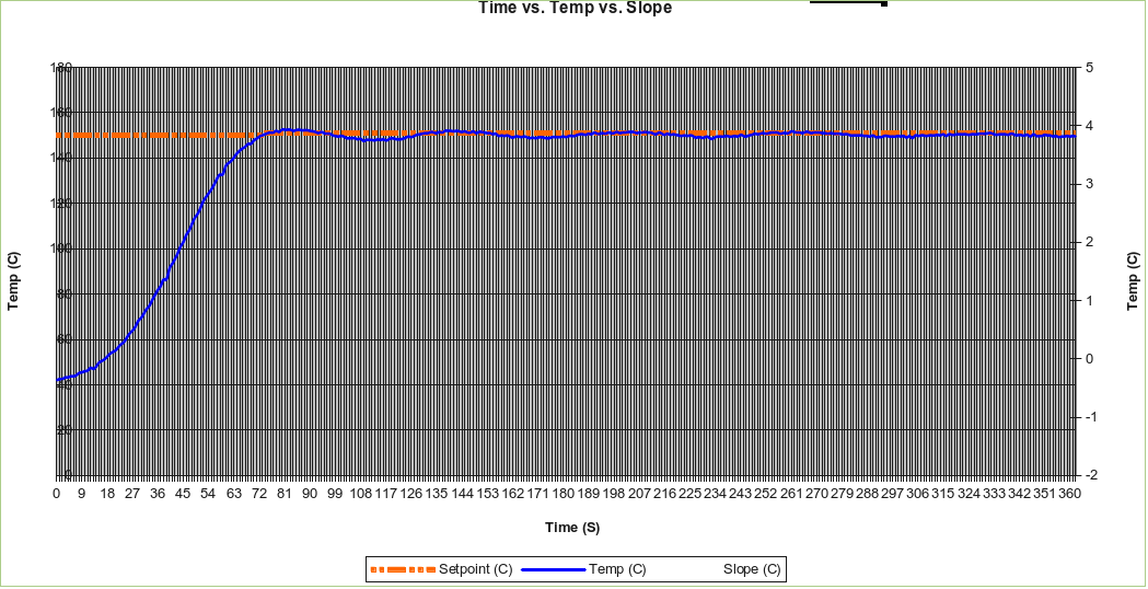 Better results after tuning
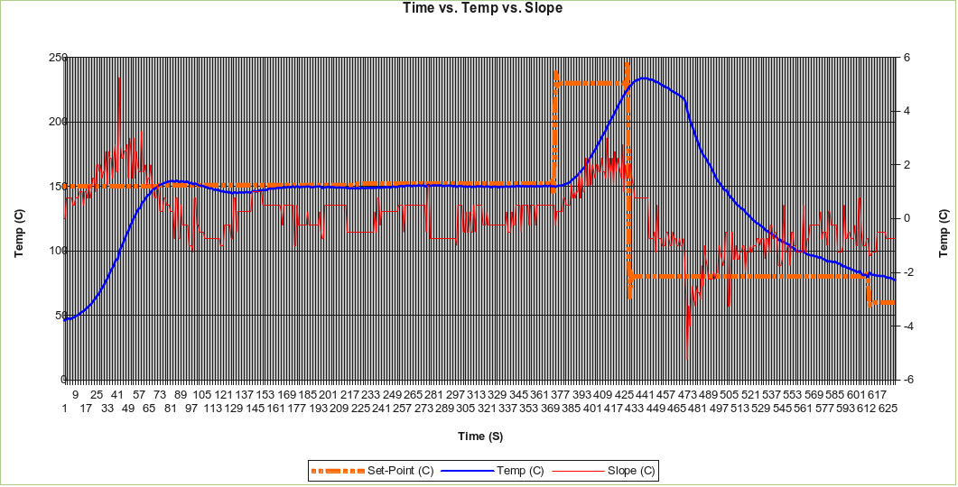 Performance of complete “pre-heat”, “soak” and “reflow” stages


 Module Interconnections
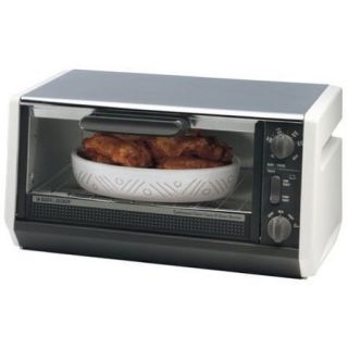 BLACK & DECKER Model TRO355
 Various PID Controllers
 TECHFX Reflow Controller
 ROCKET SCREAMReflow Oven Controller Shield
 Type-K Thermocouple
 Solid-state Relay
 ROCKET SCREAM “Mini-Ultra”
 PID algorithm
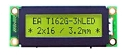 16 x 2 LCD