-
1Kite
![]()
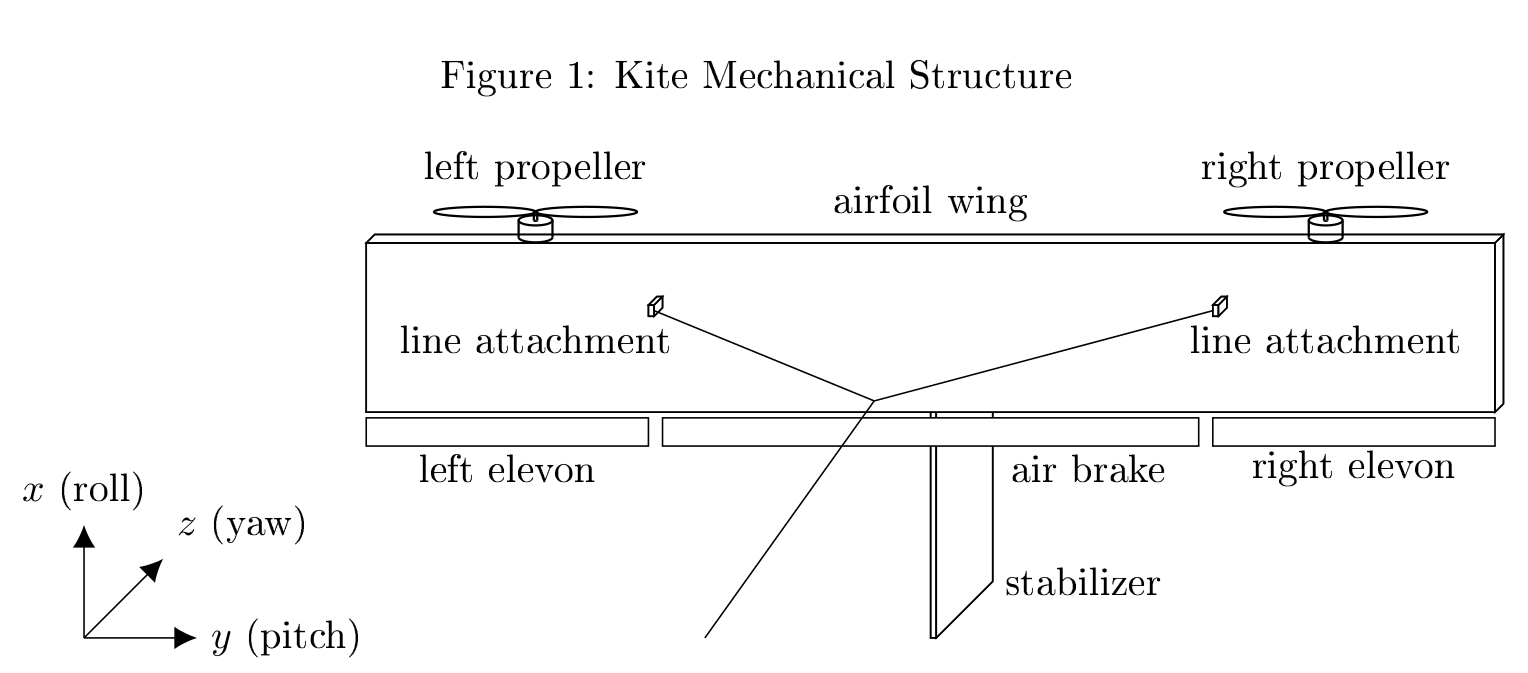
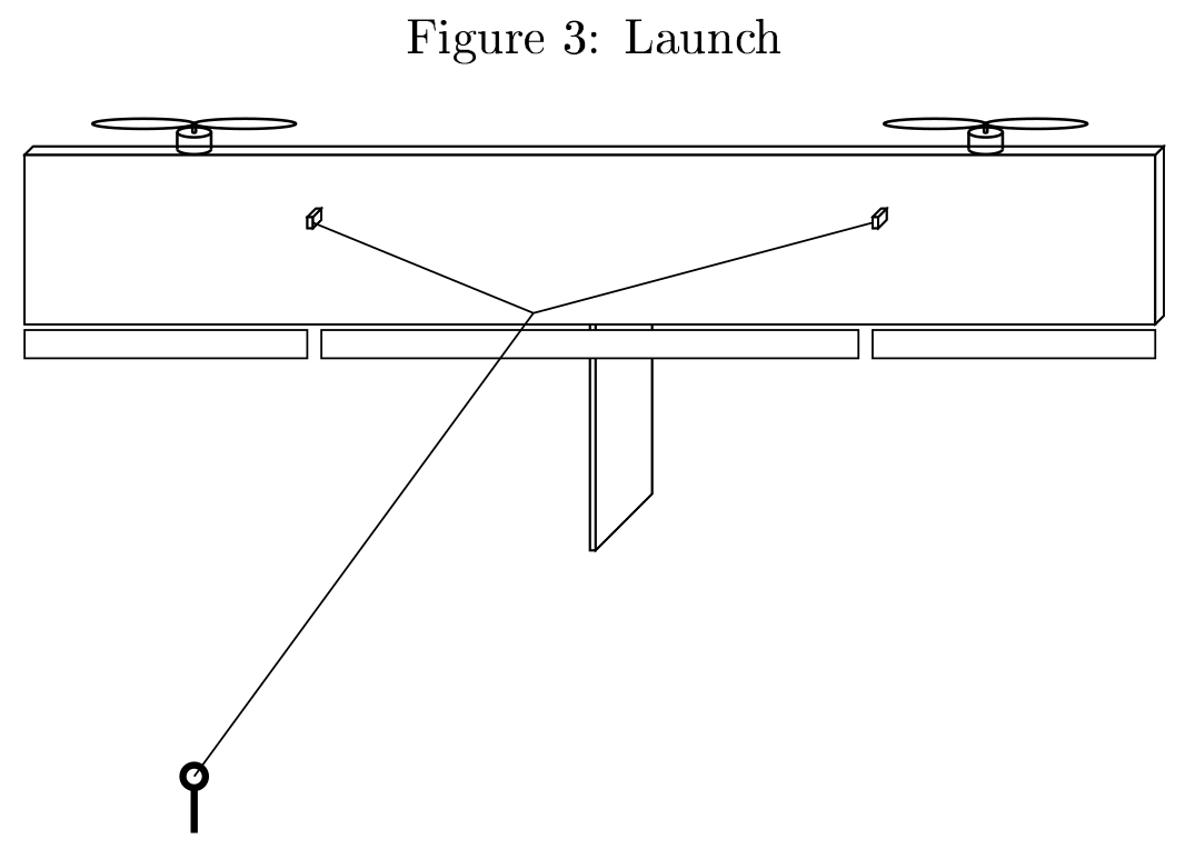
The kite is simply a wing. It has no dihedral. All our tests with diredral resulted in an aerodynamic pendulum in the launch/hover phase. When the kite moves left-right it is forced to roll due to the dihedral, which is undesired. Instead of dihedral we use two or more line attachment points as depicted in the technical drawing above. This gives good roll stability.
Two drone propellers are attached to the front of the wing. Their airflow flows over an elevon each. The propellers are attached near the wing tips to enable strong differential thrust yaw control. We use folding propellers. They turn in opposite directions (using a custom 3d-printed folding mechanism attached to originally non-folding drone propellers to avoid an undesired torque, but this might turn out to be negligible and thus unnecessary.
There is also an airbrake to enable slow but steep landings.
A large stabilizer is very important because the kite will otherwise simply not turn when flying crosswind. A rudder actually also works great for steering during crosswind flight, as you can see here:
Attached to the main wing spar extending in negative z-direction are the line attachment points. They are below the centre of gravity and the centre of pressure to ensure longitudinal stability. They should not be too far below to not interfere with pitch control while launching. They can be anywhere along the wing spar in any number, but there have to be at least two and those have to be far enough apart from the centre to provide roll stability. From those wing attachment points all lines meet at a common knot. The distance from this knot to the wing influences the roll stability and must be chosen accordingly. The aim of this design is to achieve a stiff roll stability but a gentle longitudinal stability that can be overpowered by the elevon forces.
How to build:
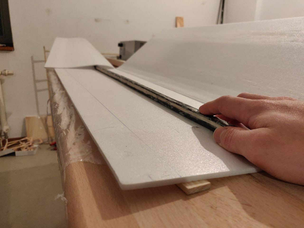
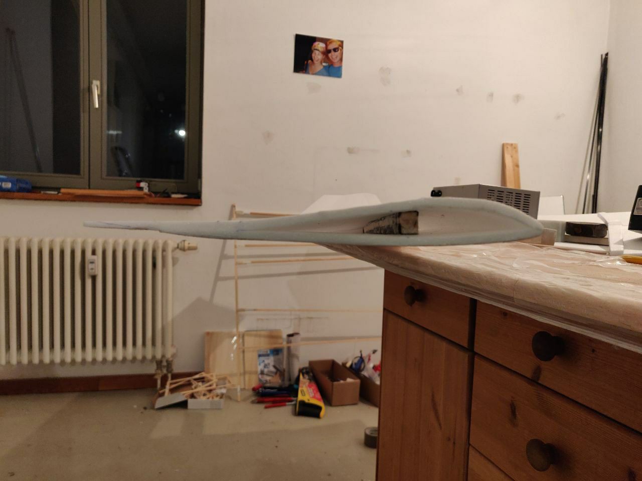
Until now we built nearly all our prototypes by folding 6mm Depron sheets around a carbon fibre wing spar (e.g. a 13mm hollow tube with 45° fibre orientation will do the job). Glue used is Uhu Por. The outside can be laminated with package tape:
![]()
![]()
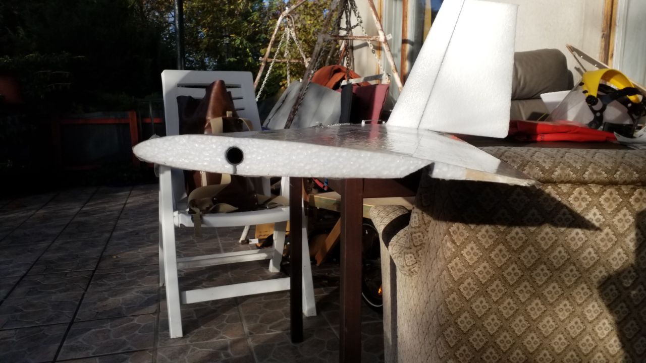
Now we started to use our hot-wire foam cutter (https://rckeith.co.uk/) with the software tool from https://www.diyrcwings.com/app/
The result looks like this:
![]()
Kite Electronics:
You need:
- 2 Motors with propellers (We use Sunnysky 4006 740 or 380Kv variant with 15 inch props)
- 2 ESCs (We use the Spedix IS30)
- an ESP32 Devkit-C v4 with an external wire antenna (the really simple ones do the job, but the PCB antenna is not sufficient)
- 4S ca. 800mAh LiPo battery
- 3 Servo motors (MG90S works fine, but beware of the fakes with plastic gears).
- BMP280 breakout board (this must be calibrated, because the BMP reacts to temperature, will add instructions soon, otherwise ask me. Also BMP doesn't like brightness differences, so must be covered in black tape or similar)
- custom PCB including an MPU6050 (the accelerometers for the three coordinate axes must be calibrated by a constant offset, brokking.net knows how, I will add instructions soon, otherwise ask me) and buck converters, see
https://oshwlab.com/benjamin.kutschan/kitepcb1_copy
for the pcb design.
- Code from
https://github.com/KitesForFuture/kite/tree/figure-eight-2
(Alternatively you could use any basic drone flight controller and somehow make our code work on that. which would be awesome!!!)
The MPU6050 should be positioned close to the centre of gravity of the kite.
Combined with a BMP280 at the ground station you could determine the height difference precisely even in changing overall air pressure due to weather.
-
2Groundstation
![]()
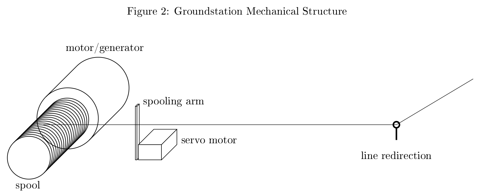
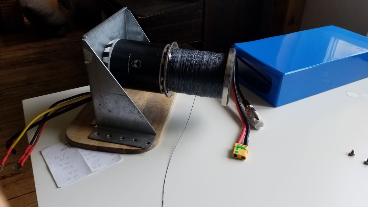
The groundstations main part is an electric motor (used as a motor and of course as a generator). We have chosen a very commonly available 3-phase BLDC brushless motor. It has a stator with 3 phases and a rotor with alternating permanent magnets.
Attached to the shaft of the motor is a spool. The line goes from the spool to a mechanism that redirects the line in any direction. This mechanism can be as simple as a screw eyelet or more sophisticated using ball bearings and pulleys.
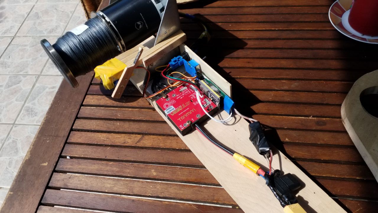
There is an arm driven by a servo motor that pushes the line sideways to ensure it is being spooled across the whole length of the spool. The line redirection is positioned such that without the spooling arm the line reaches the spool orthogonally on one end of the spool. This way the spooling arm only needs to push the line in one direction and can move out of the way when reeling out. The other direction is passively pulled by the position of the line redirection mechanism. You can also use any other spooling mechanism.
The whole groundstation assembly is being held in the ground by a large tent peg or a ground screw or similar. The closer the line redirection mechanism is to the ground the less leverage and thus the easier it is to secure the assembly to the ground.
![]()
![]()
Groundstation Electronics:
You need:
- ESP32 Devkit-C v4 with a short external antenna
- beefy 3-phase 50-90Kv BLDC (We use Alien Power System C80100 50Kv)
- VESC 6 75V with ON/OFF Switch (https://vesc-project.com/)
- 16S LiIon battery with >1kWh capacity, e.g. 20Ah.
- 1 Servo motor
- 1 Switch
- either wiring and a LM2596HV board or our custom PCB:
https://oshwlab.com/benjamin.kutschan/groundstation-vesc6-esp32
- The source code is available at https://github.com/KitesForFuture/groundstation
You could also consider a cheaper slightly lower voltage setup: 90Kv motor, FSESC 6.x (we haven't tested this yet), 12S-battery.
-
3Understanding the Algorithms
Flight Modes:
There are three flight modes: Launching the kite, flying figure eights (synonymous: Eight mode) to generate electricity, and Descending (synonymous: landing) towards the ground station. The latter can be final, meaning that the descent will be until the ground station is being hit by the kite.
First the system is in launch mode until the kite line has reached a certain length.
If this length is not being reached fast enough, it can be deduced that the wind is not strong enough and the system goes into final landing mode.
Otherwise the system goes in to Eight mode. When a certain line length has been reached while in Eight mode, the system switches to descent mode.
Either the Descent mode is final, in which case the kite will land at the ground station. Or the Descent mode will switch to Eight mode once the line length is below a certain threshold.
The flight mode is being decided by the groundstation, which counts the line length using built-in VESC functionality.
Line Angle:
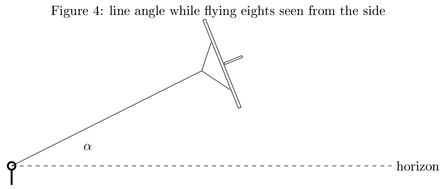
The angle of the kite line above the horizon can be calculated once its length and the height of the kite are known. The length of the kite line is being sent via Wifi from groundstation to the kite. The air pressure is being measured on the kite and at the groundstation. The latter is sent to the kite for comparison and height calculation on the kite. The line angle is being calculated on the kite.
Launch:
![]()
While in launch mode the groundstation keeps the line tension at a minimum.
The kites propellers are spinning and the kite hovers with its pointing up, slightly to the back to ensure the line being reeled out even in low or no wind.
The algorithms for stabilizing this kind of tailsitter plane are well known and have been implemented in numerous toy airplanes.
It is however important that the kite line angle does not become too steep as in this situation the bridle would inhibit the differential thrust yaw control. The kite would lean sideways and ultimately crash.
To control the line angle, the height at which the line has its desired angle (height = linelength/2 for a 30 degrees angle) is being calculated and controlled by the propeller thrust.
This simple control is sufficient to make the kite launch in a predefined angle to the horizon in the direction of the wind. In good winds this launch takes our prototype to 50 metres of height in about 10 seconds.
Transition from Launch to Figure Eights:
To transition from Launch mode to Eight mode the propellers stay turned on for a small amount of time while the line tension is being increased by the ground station. This forces the kite into a stable gliding state.
Figure Eights:
In the following video you can see the eight flying algorithm at work:
While in Eight mode the groundstation keeps the line tension high, ideally at the optimum of maximum power output but first of all large enough to enable a stable flight. It can happen that the line is being reeled in to keep the line tension up, while the kite is still flying figure eights. This can happen in low wind scenarios in the curves of the figure eight.
![]()
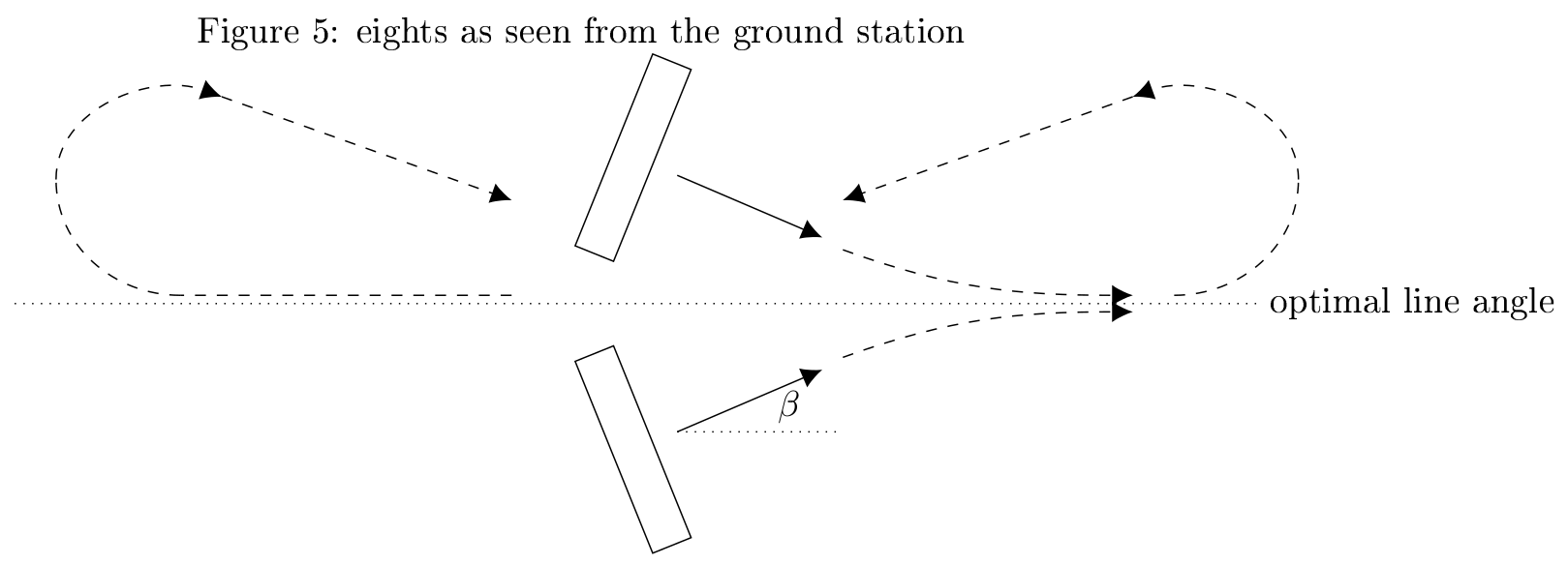
While flying figure eights the angle α between horizon and kite line needs to be controlled. Seen from the groundstation the eight looks as in Figure 5. We view an eight as two curves and a somewhat horizontal flight in between.
![]()
During the horizontal part the nose of the kite can be controlled to point slightly up or down depending on whether the kite line angle is too large or too small. A P-controller sets this nose angle β depending on the deviation from the line angle α.
During a turn this nose angle is changed at a predefined rate (which we call turning speed).The angle β is held by a common PD-Controller using the aileron functionality of the elevons. Also a rudder could be used and we found this to also work very well.
Descent:
Here you can see out current state of the autonomous landings, still a bit bumpy but hitting us (i.e. the ground station) with good precision:The kite descends in the same orientation a normal aircraft would when landing.
During the descent phase the line tension is kept just high enough to keep it straight by rolling the kite slightly in case of flying too far left or right.
Steering the kite left or right is being done by the aileron functionality of the elevons. When the kite threatens to fly to far left the line tension and the bridle cause it to roll. This roll is being sensed by the orientation sensor and used as an input to a P-Controller affecting the elevons. A D-term was not neccessary during our test flights, possibly because the wing produces enough drag in roll direction.
The line angle α Figure 5 needs to be controlled by the elevator functionality of the elevons. The desired height is calculated for example as linelength*0.2 to achieve a descent with 20% steepness. Then the desired dive angle of the kite is being set by a P-Controller relative to the height error. The actual dive angle is then controlled by a PD-Controller relative to the error between the actual and the desired dive angle.
Transition from Descent to Figure Eights:
To transition from Descent to Eight mode the desired dive angle is being set to a positive number to make the nose point up. Then Eight mode can begin from a well defined orientation and laminar air flow.
Kites for Future - Flying Wind Turbine
A flying wing drone that can periodically pull a tether + a generator on the ground that acts like a rowing machine = Flying Wind Turbine
Discussions
Become a Hackaday.io Member
Create an account to leave a comment. Already have an account? Log In.