The communication interface
As said, there were some rumors that the CAN bus is used for the communication between the battery and the drone. So I ordered a cheap logic analyzer and a suitable bridge circuit (CAN <-> serial) to analyze the communication and maybe mimic it. While waiting, I got my hands on an oscilloscope and wanted to check if these rumors are really true. But the measured signals made me a bit suspicious...
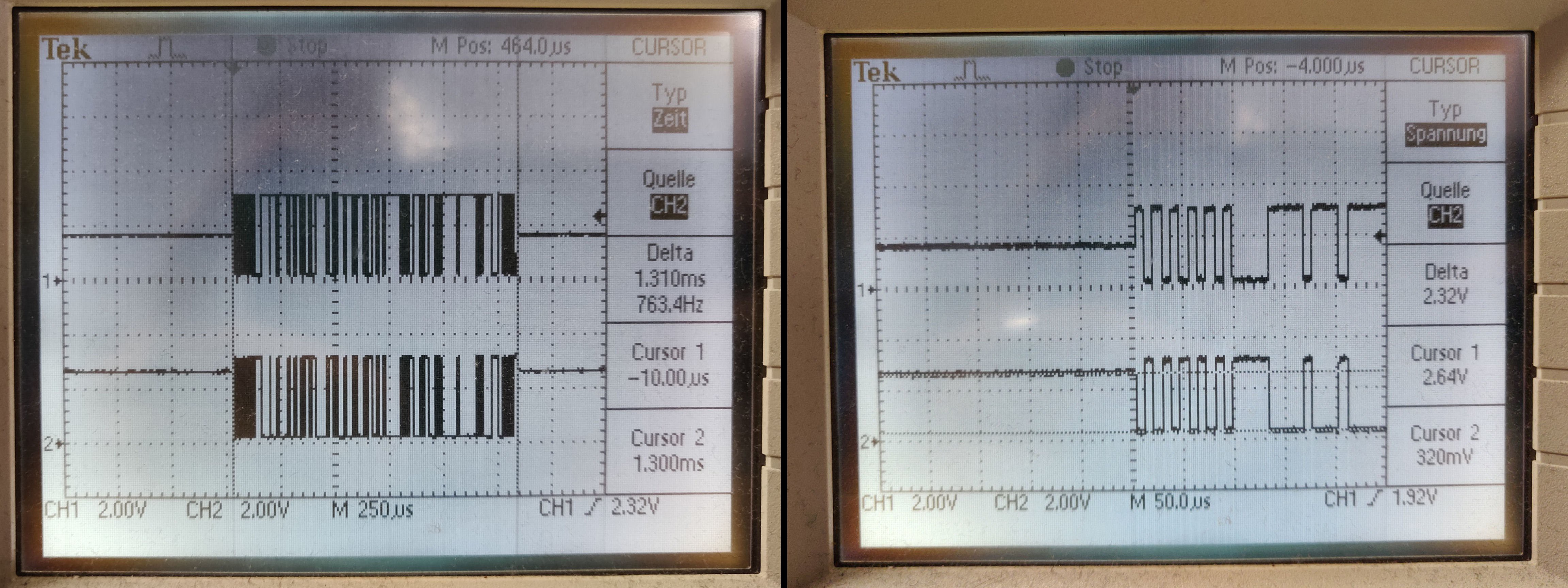
The CAN bus is a new topic for me, but all the schematics I've seen so far looked a little different. In these schemes, CAN HIGH never went to ground. In addition, the low maximum voltage of approx. 3.2 V made me a little nervous, since the bridge circuit I ordered had an operating voltage of 5 V. As I was told that the CAN bus should be tolerant to 5V and what matters is that the difference between CAN HIGH and CAN LOW is at least 2V in the dominant state.

But I was still afraid of frying my drone/battery so I decided to take a closer look at the smart battery control board. Unfortunately, most ICs were covered with a coating that made the labeling very difficult to read. After a while I could figure out all but one of the ICs. And none of them were capable of CAN bus communication. So it had to be the last one. I was able to gently scrape off the coating with a scalpel without damaging the label. After this I could recognize a SN65HVD75 which is a RS-485 communication IC. Ok, RS-485 instead of CAN. Very similar but not quite the same.
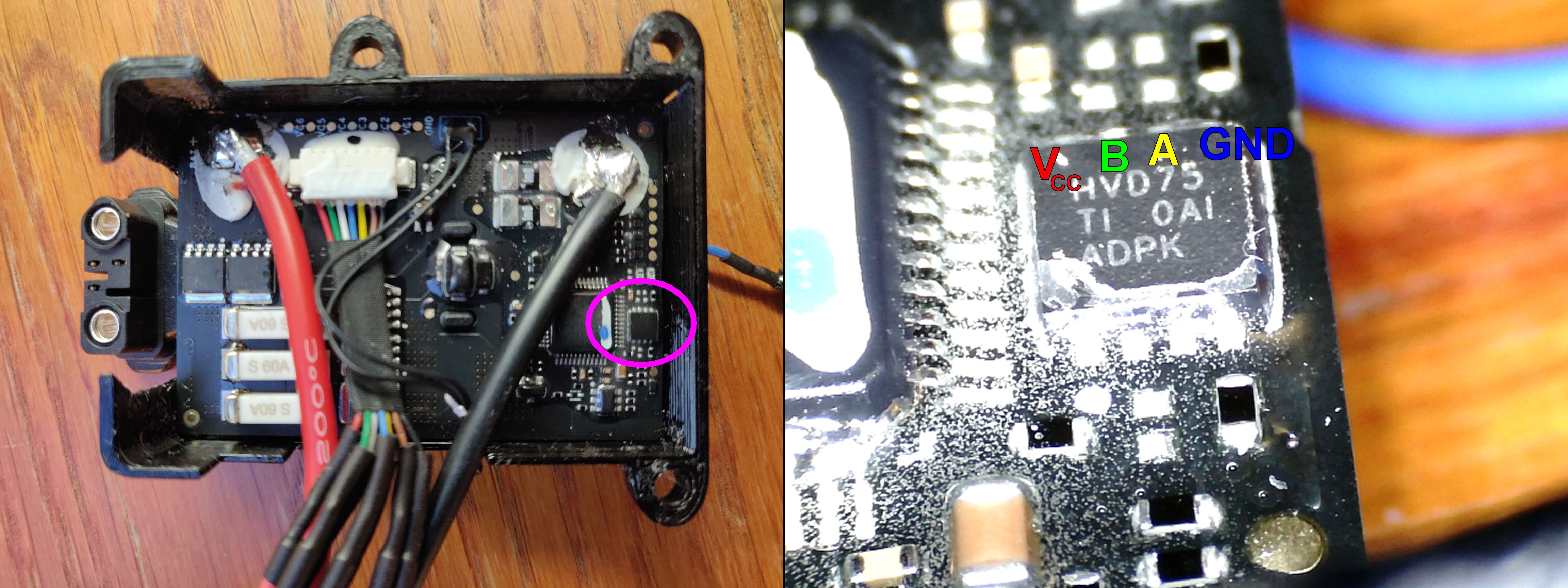
With the help of the manual (https://www.ti.com/lit/ds/symlink/sn65hvd78.pdf) the communication pins A and B could be identified. As assumed, these pins are connected directly to the drone <-> battery connector.
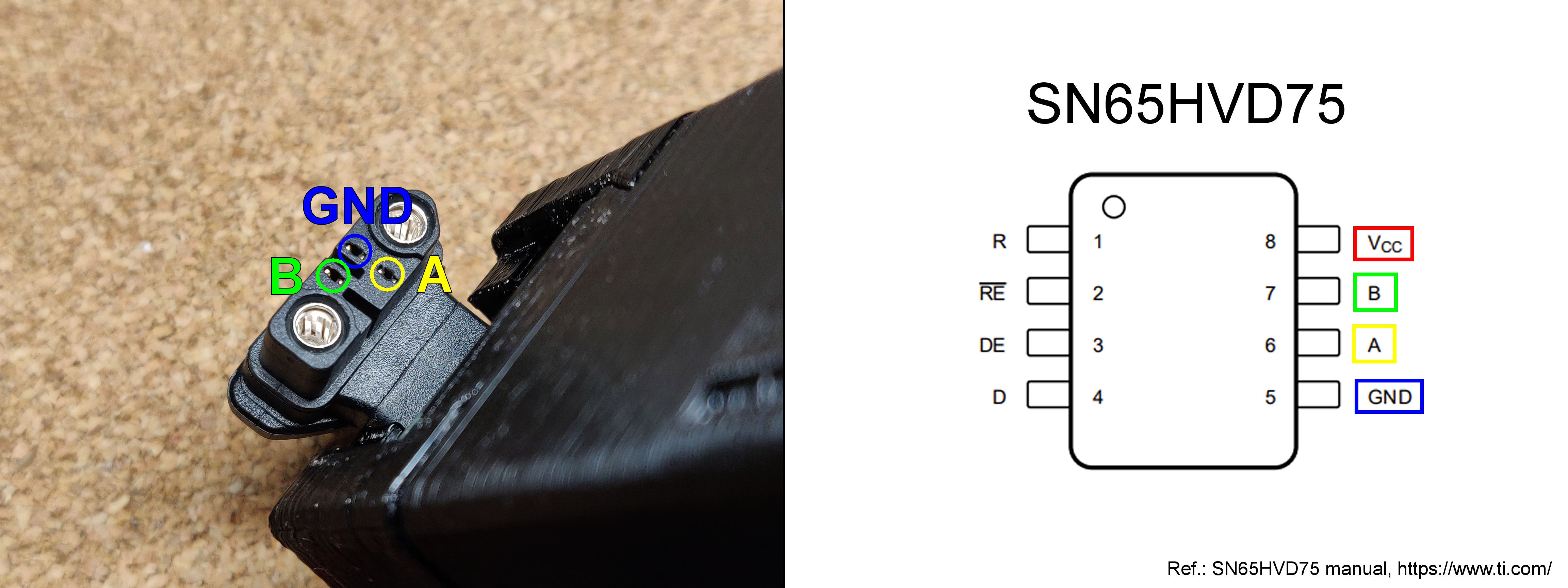
Using my logic analyzer I was able to easily measure the signal on pin A. Interpreted as asynchronous serial communication (115.2 kbit/s, 8bits, 1 stop bit, no parity, inverted/non-inverted depending if you use pin A or B) it turned out to be DJI's duml protocol.

And now comes the hard part
With that I could read all communication between the smart battery and the drone. So far so good... But the goal was to mimic the communication so that I can tell the drone what I want and the drone will accept that. To do this, I needed to be able to read and understand the drone's requests and to respond accordingly. Also, I needed to find out if there are any requests from the battery to the drone that the drone is expecting but don't ask for, "pings", etc.
Sounds like routine work, but the problem was that the duml protocol is widely undocumented (no official documentation). It is mostly reverse engineered knowledge that is not complete. To dig a little deeper, I recorded 12 minutes of drone <> battery communication (16209 duml messages, downloadable in the files section of this project). Wireshark which was suggested to me is a great tool to help decoding the messages. But there are still many unknown CMDIDs, data fields that I can't be decoded, etc.
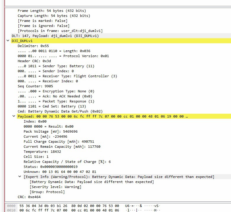
One example: A request from FLYC to Battery with the CMDID GetPushDynamicData (55110492030bb126400d02000000004b03) followd by ACK from Battery to FLYC with the datafield 0000765300006cfcffff7c070000cc0100004801061900000000030000001301640000470281020000" (5536043d0b03b126800d020000765300006cfcffff7c070000cc010000480106190000000003000000130164000047028102000064e4).
So the question is: What does 0000765300006cfcffff7c070000cc0100004801061900000000030000001301640000470281020000 mean? Battery status? Battery voltage? LiPo cell voltages?
Wireshark tries to decode the data field, but returns unrealistic values. The warning is another indication that something is out of date...
Due to the limited space I have to split up here. So check out the logs for the rest of the project :)
 AirCruiser

 Thomas Flayols
 Rory
Rory
 Dead Rat Productions
 Neal
Neal
This is great work