-
Project finished (for now)
01/13/2023 at 15:41 • 0 commentsI think I've wrapped up how much I'm going to do for the project. I updated the code so the display looks realistic. Has a semi-randomness to it that looks like it's doing some kind of computation. I updated the layout to reflect some changes that I think would really help, but I don't think I'll build another one. I still need a case or some kind of mounting for it, but I can just get by with a few screws to prop it up for now. I'm pretty happy with the result on the front side. I hoped the back side would still look clean, but there's too many patch wires. I guess I still have blank boards...
I put up the files on PCBWay to order in case anyone wants one. They're kinda big so a little expensive, but just order black silkscreen!
https://www.pcbway.com/project/shareproject/Wargames_WOPR_prop_PCB_2d23a9d9.html
-
Assembly complete
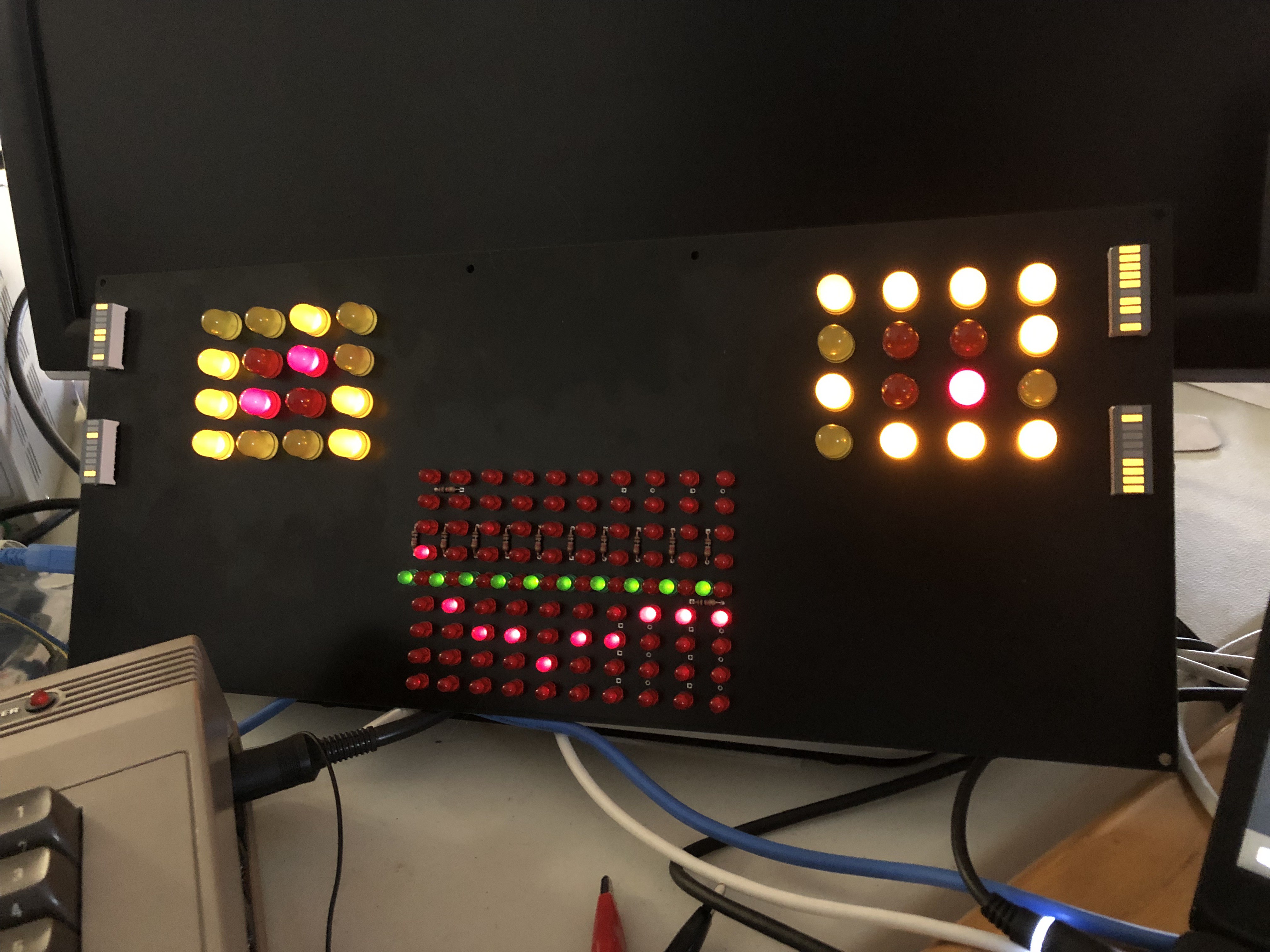
12/19/2022 at 20:56 • 0 commentsFinished hardware assembly and some software. I'm pretty happy with the result.
![]()
I have the center array charlieplexed. In the movie, only one red LED is on per column, so it won't get too dim. The eyes and bar arrays are driven by serial shift registers. I also included a buzzer in case I ever get the software running well enough to play a tune from the movie. Maybe digitized voice eventually? But that could be taxing the Arduino too much.
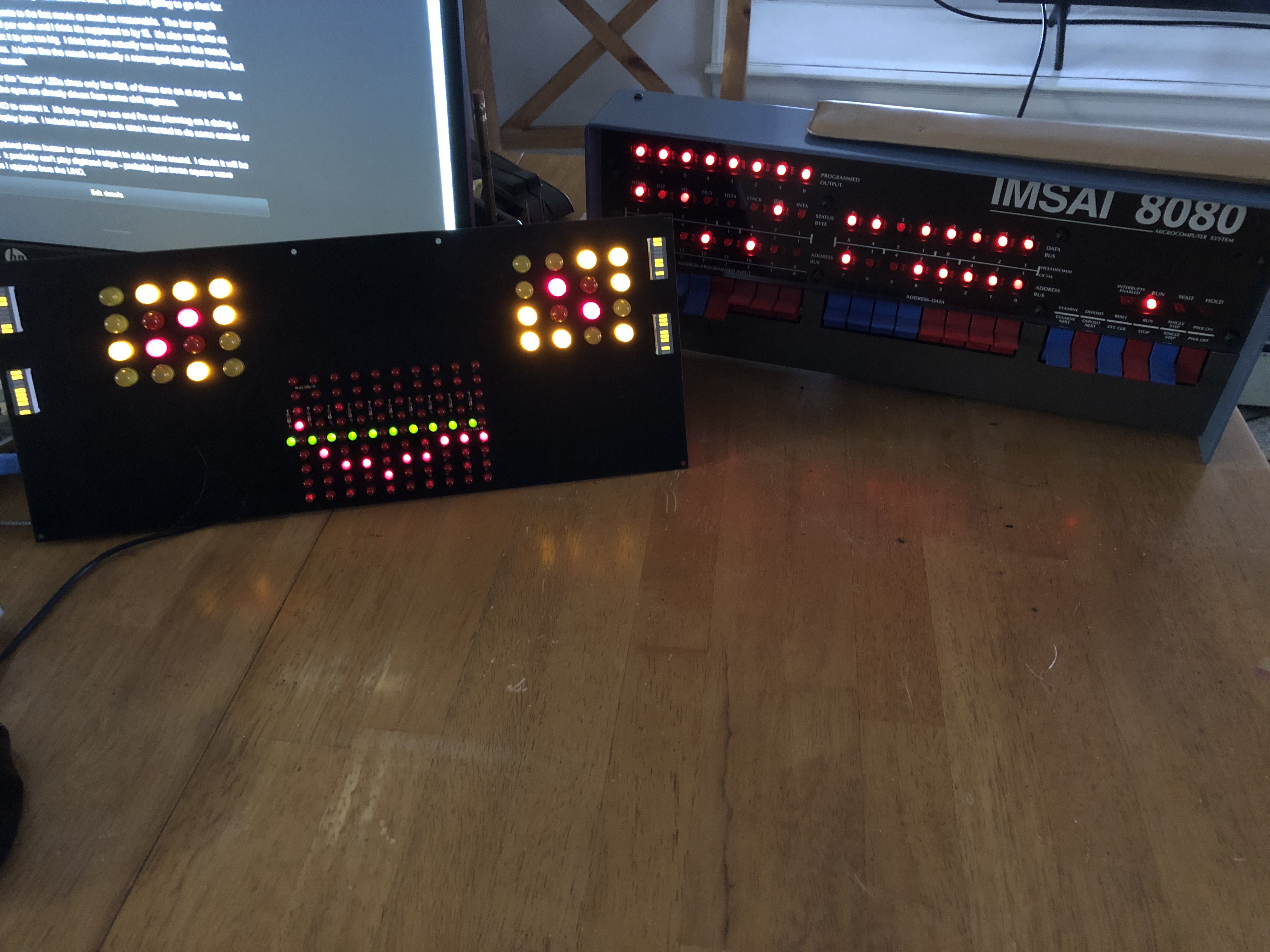
And obligatory photo with the IMSAI 8080 clone.
![]()
I tried to make the eyes update similar to the movie. The center array needs more work to make it more movie-like. I assume it was taken from an old graphic equalizer display, so it's a somewhat continuous line.
I won't show the back side because it's loaded with bodge wires. I learned not to solder on LEDs, and then clip off the leads. It broke a few of the traces at the through-hole pad. I could also reinforce them with some large teardrops going into the pad. I also had my MISO and MOSI swapped. The bit-banged SPI was not fast enough and showed a noticeable flicker, so I had to rewire it.
For the released layout I need to make some changes:
- Swap MISO and MOSI
- Increase reference designator text size
- Change SOIC footprint to include SOP package size for shift registers
- Change SMT resistor array to an SOIC package for easier soldering
- Put long lead/short lead indicators in silk screen for easier assembly
- Add 3.3V and 5.0V test points
- Add teardrops at through-hole locations to lower risk of breaking
Now just need to make some kind of a case for it.
-
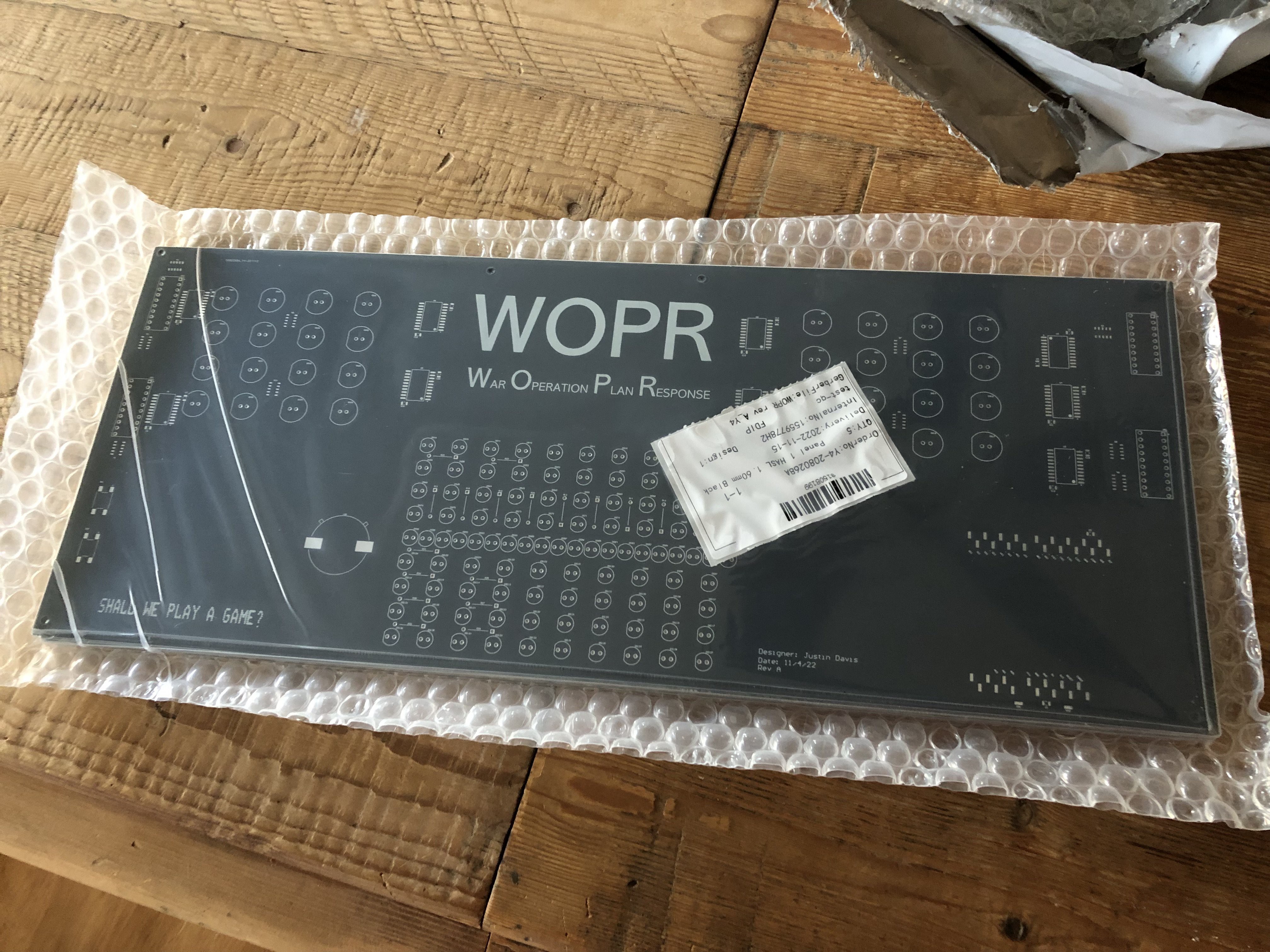
PCBs received
12/02/2022 at 13:02 • 0 commentsAlways seems like forever, but got the PCBs in. They look great. I found a couple issues off the bat. The chips I ordered were the wrong package size. I designed for SOIC and got SOP. Digikey has them listed wrong. And the datasheet only indicates they are different in one small place. There's not even a mechanical drawing of the SOP on it. Anyway, it's still solderable, but it takes more care. Maybe I will update my footprint to be compatible with both.
I also discovered I swapped my MOSI and MISO. Not a huge problem, but now I'll have to bit-bang the SPI since those pins are hardwired. Which makes it slower. If it's a big problem I may cut traces and rewire.
Next up assembly.
![]()
-
PCBs ordered
11/14/2022 at 17:02 • 0 commentsOrdered PCBs from EasyEDA/JLCPCB. They were fairly cheap compared to other places. The board is large, so any place that charges by size was expensive. It was $31 for 5 not including shipping. The size is 400x164mm or 15.7x6.5 inches. That's a long board.
One problem I had was mounting. There's two visible screws in the middle of the top, but that's it. So I put four holes in the corners and made the board slightly larger. I think I need some kind of picture frame or custom frame. It's definitely too big for my 3D printer. Maybe I can print one in pieces.
Wargames WOPR prop PCB
Remake of the WOPR computer "face" from the movie Wargames