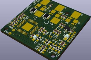
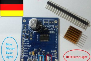
The onboard microcontroller ATtiny261A generates 3 Phase (3 channels PWM for U V and W phase) 32KHz PWM from Timer 1. This result in resultant vector A.K.A position of the rotor of the BLDC motor. By changing the Sine angle (Step through Sine LUT). We can precisely control the angle of the rotor. Of course, the precision is depends on PWM resolution (In this case is 8 bit instead of 10 bit) and Sine LUT resolution (Which I went with 256 Sine steps).
The code I wrote use I2C to communicate between the Master device (Arduino Uno or anything) and Slave device (ATtiny261A) with 7 bit address of 0x30. Master send 3 bytes command. First byte is the direction and the rest are step count.
Demo Video :
 TinLethax

 Alberto

 Matthew Moore
 AVR
AVR
"This isn't 100% FOC"
That's quite an understatement.
Without feedback it is not FOC at all.
Motors inherently have a lot of elasticity between rotor and stator, which means it will never be accurate when there is any load variation. Just put on a lever and rotate the axle a bit.
Without feedback, the system will also be very inefficient. It's easy to push the full motor current through the motor, without it even moving. Without position feedback the controller has no idea about the load on the motor, and thus also does not know how much current the motor needs. Even simple 6-step commutation with hall sensor feedback is much better then no feedback at all.