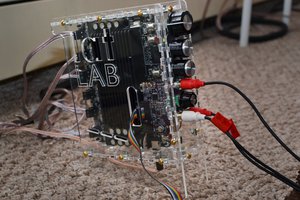
This board includes:
- ADC with input amplifier
- some power supplies
- simple graphics controller for LCD implemented in FPGA
- signal processing implemented in FPGA: conversion to baseband, filtering, downsampling, RMS calculations
- microcontroller which controls the whole system, does calculations on the results from FPGA, controls keyboard and display.
Design documentation is attached (see "Files")
Files
Digital v2 design pack.zip
version 2 - design files and description of digital part of spectrum analyzer
- Changed FPGA (obsolete spartan 3) to LFE5U-25F-7BG256I (note: wrong part number on schematic)
- No SRAM for samples processing (different algorithm)
- Some changes of power supply (eg bucks instead of LDO, large bulk capacitor for power off sequencing)
- Some changes of input amplifier (only differential amplifier and buffers, filter removed - to be done on IF board)
- Other fixes planned after rev1
FPGA:
- Changed IF frequency (3->2.5MHz) and sampling frequency (20->10MHz) so the IF is 1/4 of sample rate
- This makes multiplication by sin/cos is simpler - the signal is multiplied by 0/1/0/-1
- The signal is not stored in memory and processed by the same filter but now it's filtered continuously by separate filters (7 IIR filters: 1M/300k/100k/30k/10k/3k/1k). This takes a lot of FPGA resources (the design barely fits FPGA) but should be faster and no external SRAM is needed. The IIR filters are 5-sections biquad (each), direct form type I, with additional feature of dynamic scaling feedback signal before/after 18x18bit multipliers (which reduces errors, e.g. DC offset after many filtering stages).
- Other changes required to make it working (e.g. improvements of communication synchronization between uC and FPGA, optimizations, adjustments of graphics module for different VHDL version, DCM, clock constraints and others...)
Software:
- With faster processing in FPGA, the main limitation of sweep time is microcontroller - the code was optimized, including change from floating point to fixed point numbers representing frequency and magnitude. It's still way too slow and incomplete and it's work in progress (e.g. missing VBW which seems to be needed in some of cases).
This version has different IF so it's not working with existing IF module which needs to be redesigned.
First the signal is multiplied by 3MHz sin and cos digitally, then FIR filtering with simultaneous dropping samples for decimation (both I and Q signals). After one or more filtering/decimation stages, RMS is calculated from remaining samples - that's all. About 120 taps (probably the filter is currently too good for the hardware so it's just some initial value to be tuned later).
Are you using only FIR filters before each decimate by 10 stage? How many taps?