 Supplyframe DesignLab
-
1Overview
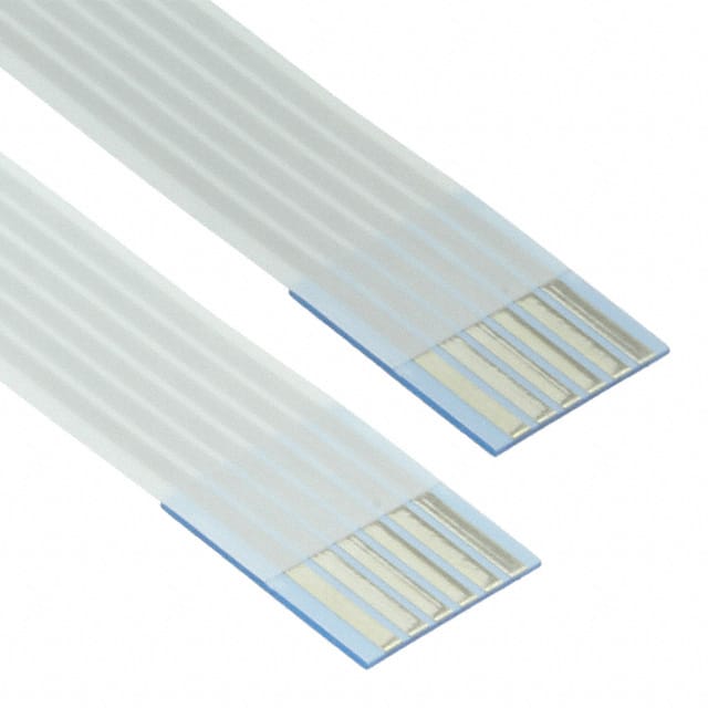
Controller and Lamp are connected with a ribbon cable (see Data Sheet). There are two available cables: 6 and 10". Depending on your design, you may choose one or the other.
![01516702xx]()
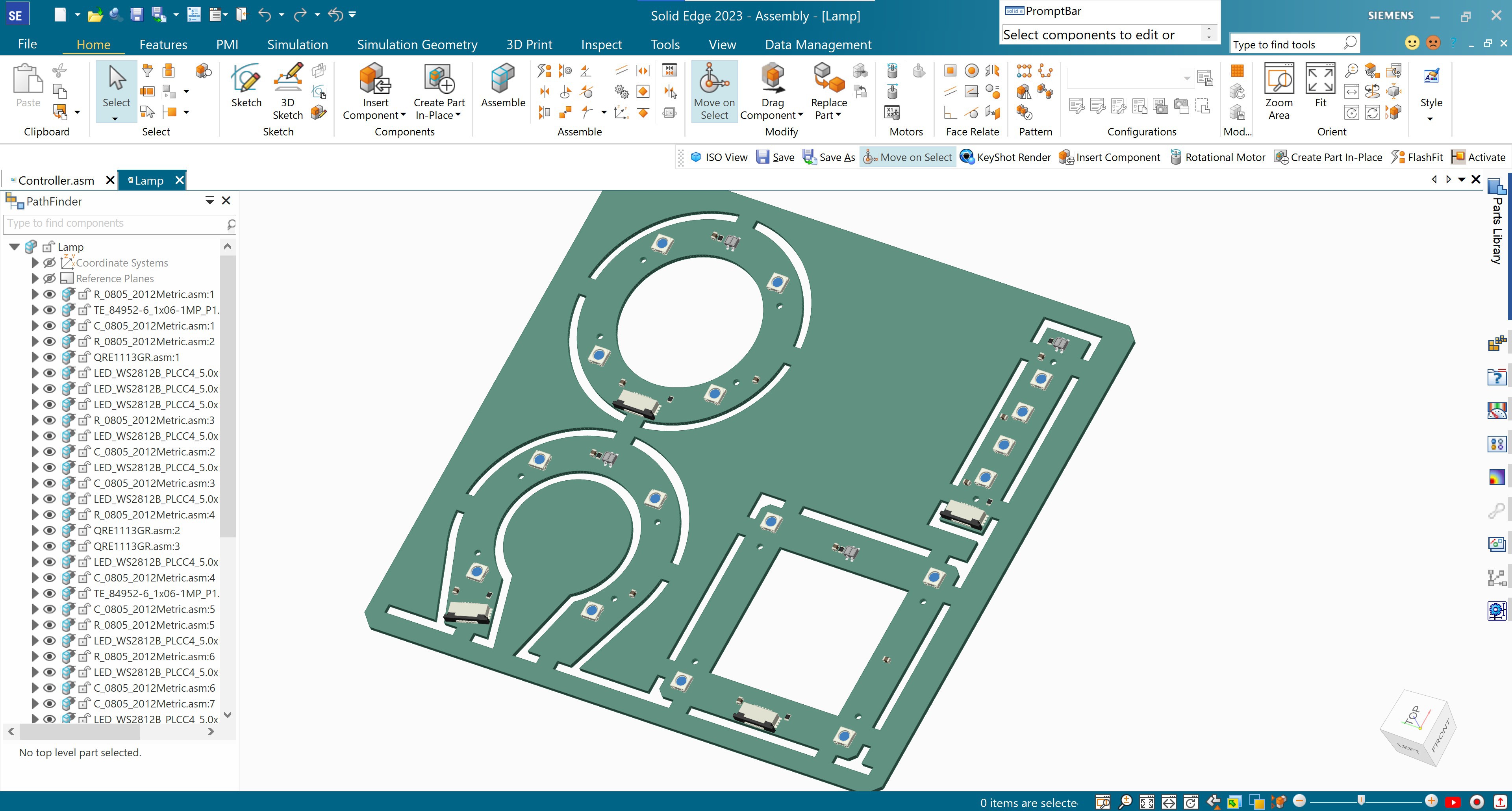
The same goes for the four Lamp Board shapes. All have the same components. Please choose the one that better fits your design concept.
![]()
The Controller Board is one-sided. This means that all the components are on the top and it can lay flat on a surface. This is where the Raspberry Pi Pico W and batteries are found.
There are a few important design considerations that we will define in the next steps.
![]()
-
2Controller Board
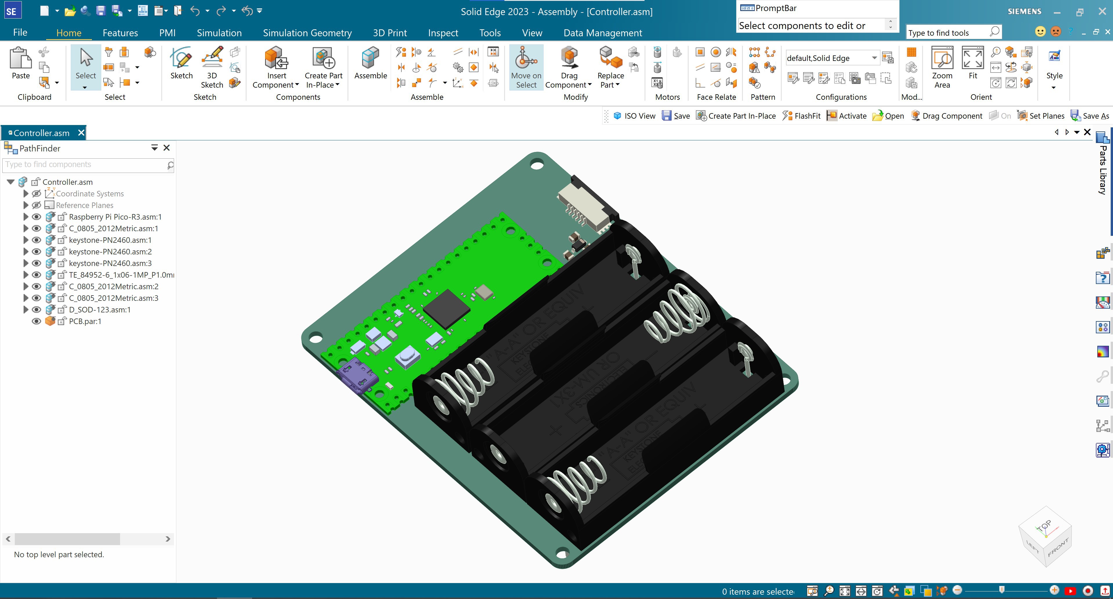
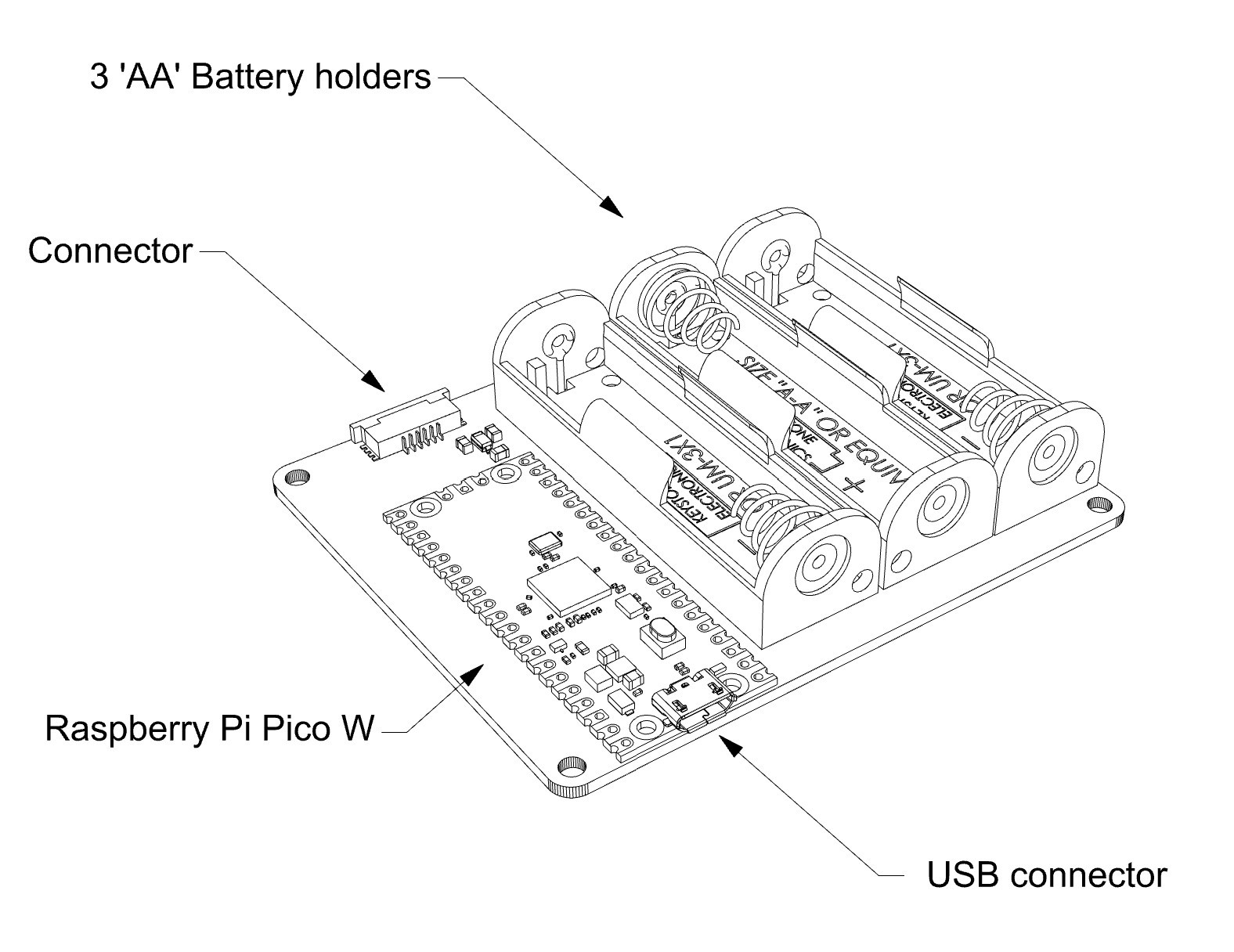
The Controller Board has a few important components and attributes to be aware of when designing your Lamp project.
- The Raspberry Pi Pico W board. This small but mighty development board has a RP2040 microcontroller and Wi-Fi connectivity. This brings fantastic possibilities for your project. More on that later.
- 3 'AA' battery holders. Ideally, these should be easily reachable. Batteries can be rechargeable.
- Ribbon cable connector.
- USB mini port. Your design will determine if this port has to be accessible at all times or not. However, we will use it to flash (upload) firmware to the RP2040.
Assembly holes and precise dimensions can be found in the DXF, AI, and 3D STEP files.
![]()
-
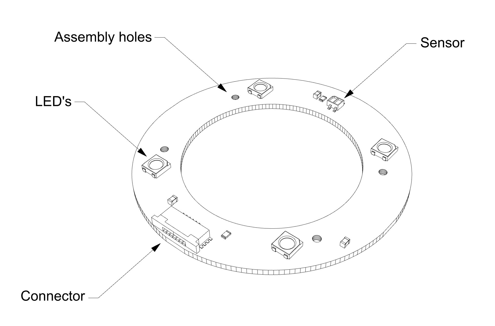
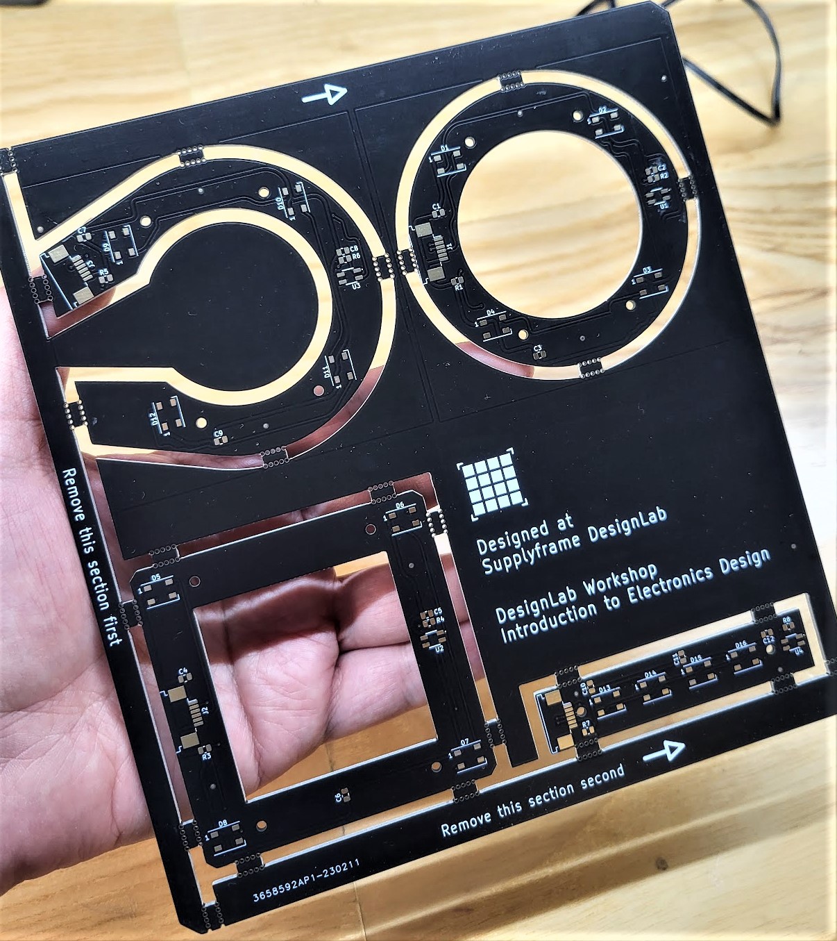
3Lamp Board
As mentioned earlier, all Lamp Boards have the same components. Here is a quick overview, before we go into more detail:
- Four addressable RGB LED's. RGB means that they can cast Red, Green, Blue light, and everything in between. Addressable means that each one can be operated separately.
- One Mini Object Sensor. This sensor can detect motion or objects near it. It has a range of 5 mm. If you want to learn more about it, you can check out Sparkfun's breakout board listing.
- Four assembly holes.
- One ribbon cable connector. This cable supplies power and sends and receives data to and from the Controller Board.
Just like the Controller Board, assembly holes and precise dimensions can be found in the DXF, AI, and 3D STEP files.
![]()
-
4RP2040
Let's talk a little bit about the main board, its microcontroller, and why they are relevant.
Development Board
The Raspberry Pi Pico W that we are using can be considered a development board, meaning that hardware designers use it to iterate concepts quickly for projects, products o experiments. Think of development boards as "mini electronics workshops". Some have more bells and whistles than others. There are many kinds, but in general, in addition to the microcontroller, they provide connectors, power source, and built-in components for specific functions, all in a standard shape.
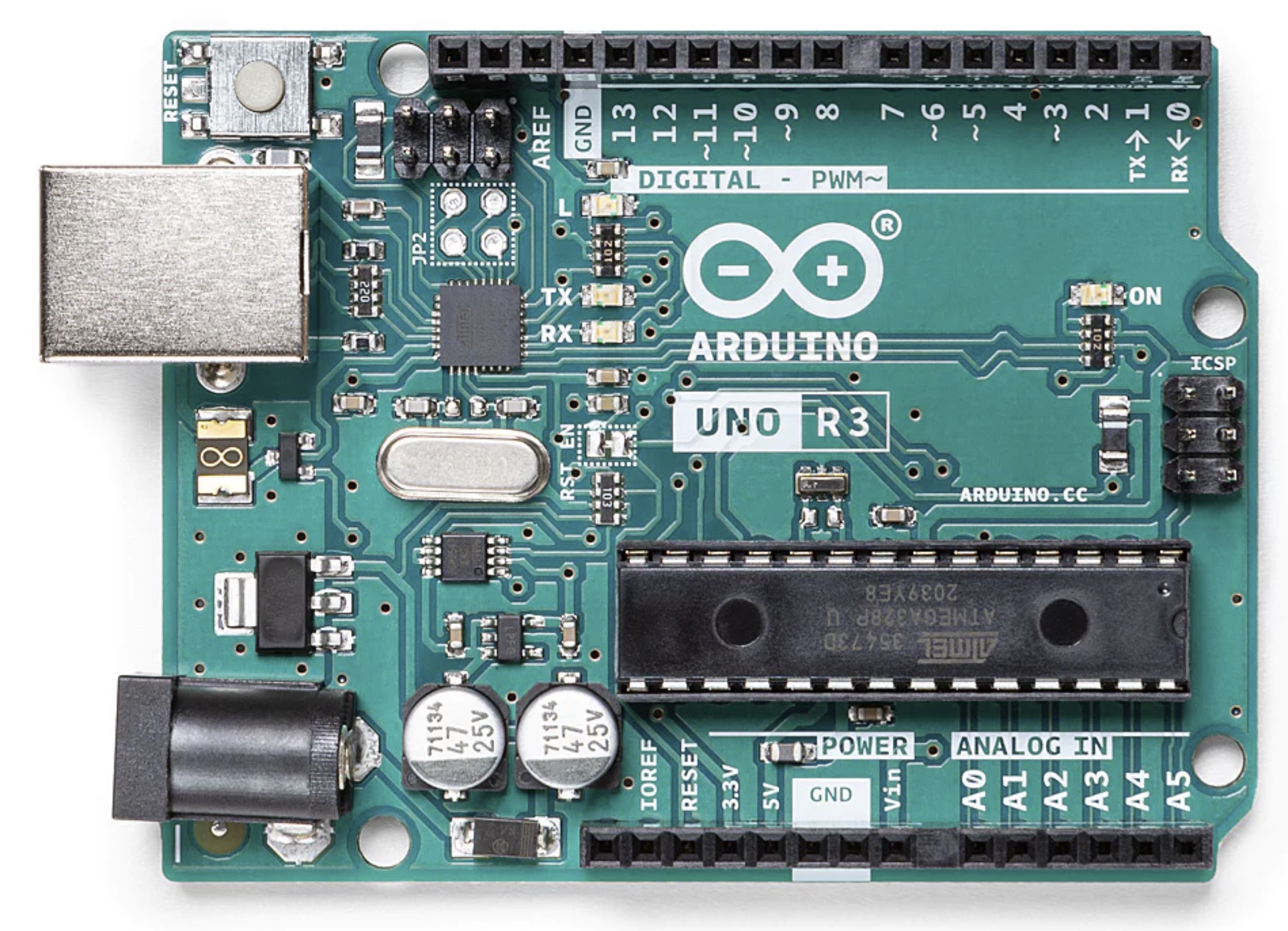
Below we have two popular development boards: the Raspberry Pi Pico W, with a RP2040 microcontroller, and an Arduino UNO R3, with an ATmega328P microcontroller.

![]()
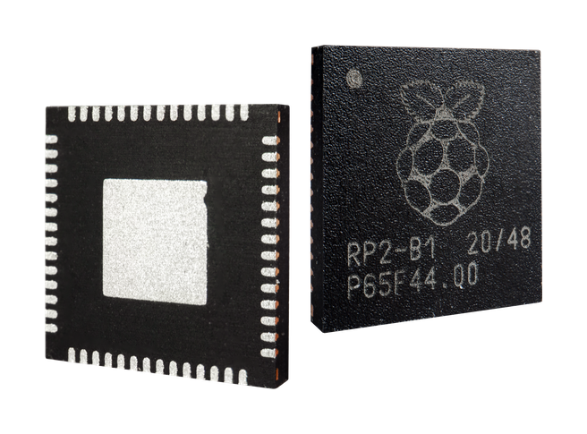
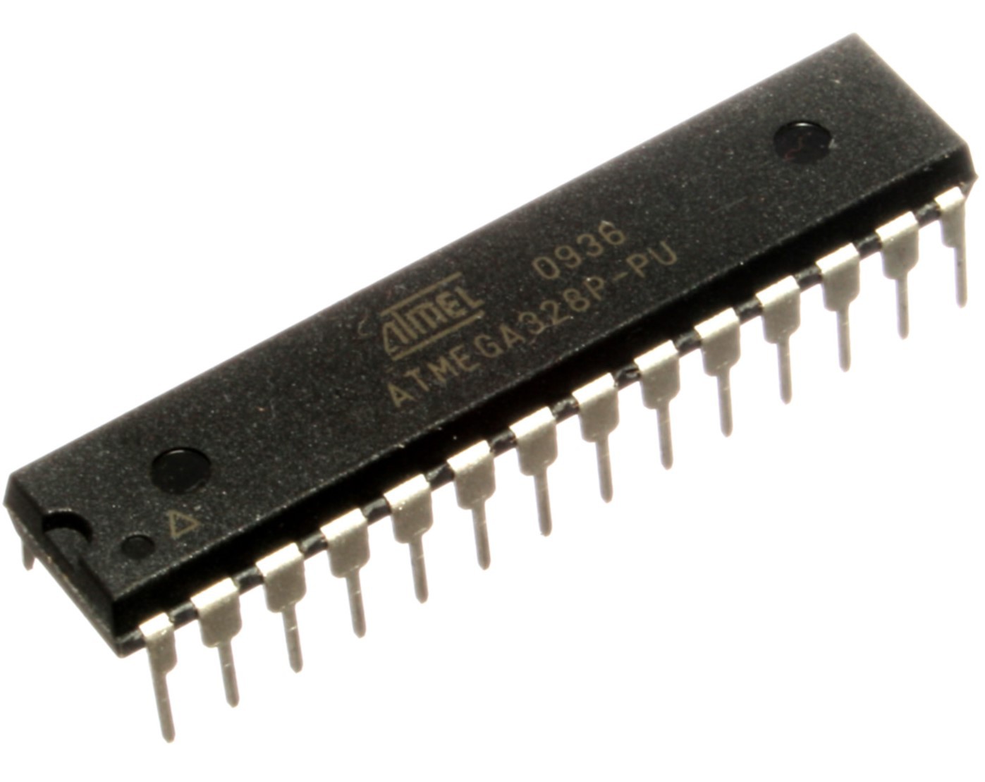
Microcontroller
The microcontroller in a development board is the actual brain of your whole array. The more complicated a system is (for instance, a robot), the more "minibrains" you will need. Microcontrollers are small computers that perform one task at a time, but they do it quickly and efficiently, thus not needing as much computing power or energy, as say, a microprocessor of a computer that has to deal with graphic interface, sounds, connections, etc.
![]()
![]()
Impact on your product
The microcontrollers that we discussed above can be bought separately and put in your own Printed Circuit Board. However, their architecture may be different, and the code used in one may not work on the other. You may be very happy and jolly working on a project with a development board that you love, only to find out that there is no stock of its particular microcontroller, and the lead time is long. Those are some of the few reasons that you need to keep in mind when selecting a development board.
-
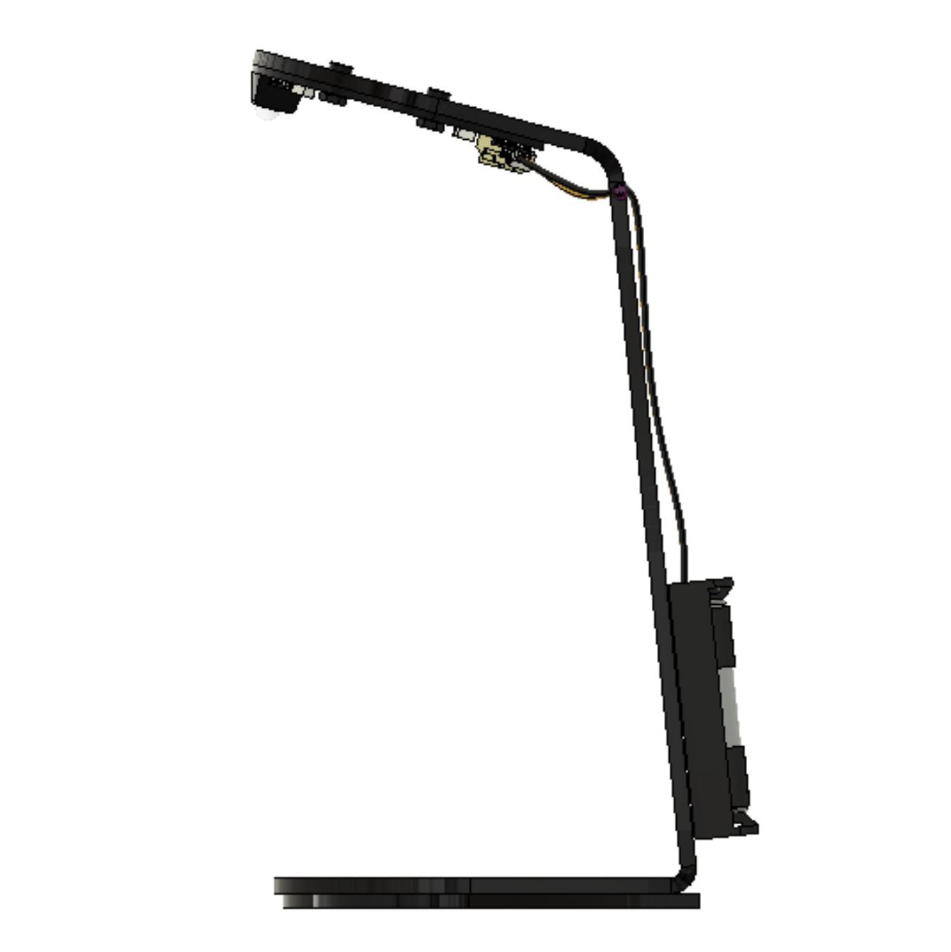
5Product Design Inspiration
This workshop was derived from the original PCB Lamp.
Design
This time around, it is the participants of the workshops who get to define how the Lamp will look like! Participants will be able to choose between four shapes for the lighting element. The controller is the same.
![]()
If you study(ied) design or are an enthusiast, you will probably recognize a pattern here. These shapes took a bit of inspiration from Bauhaus' study of shapes. Now, between you and me, we did make a triangle PCB but it did not add that much. So, we kept the circle, a square, and added two more forms: a straight line, and the "horseshoe" shape from the previous workshop.
Functionality
In the first iteration of this new workshop, the lamp will be tap-activated (still pending to confirm if it will work), or have a simple automatic pattern. You may change the code to have it do something specific!
-
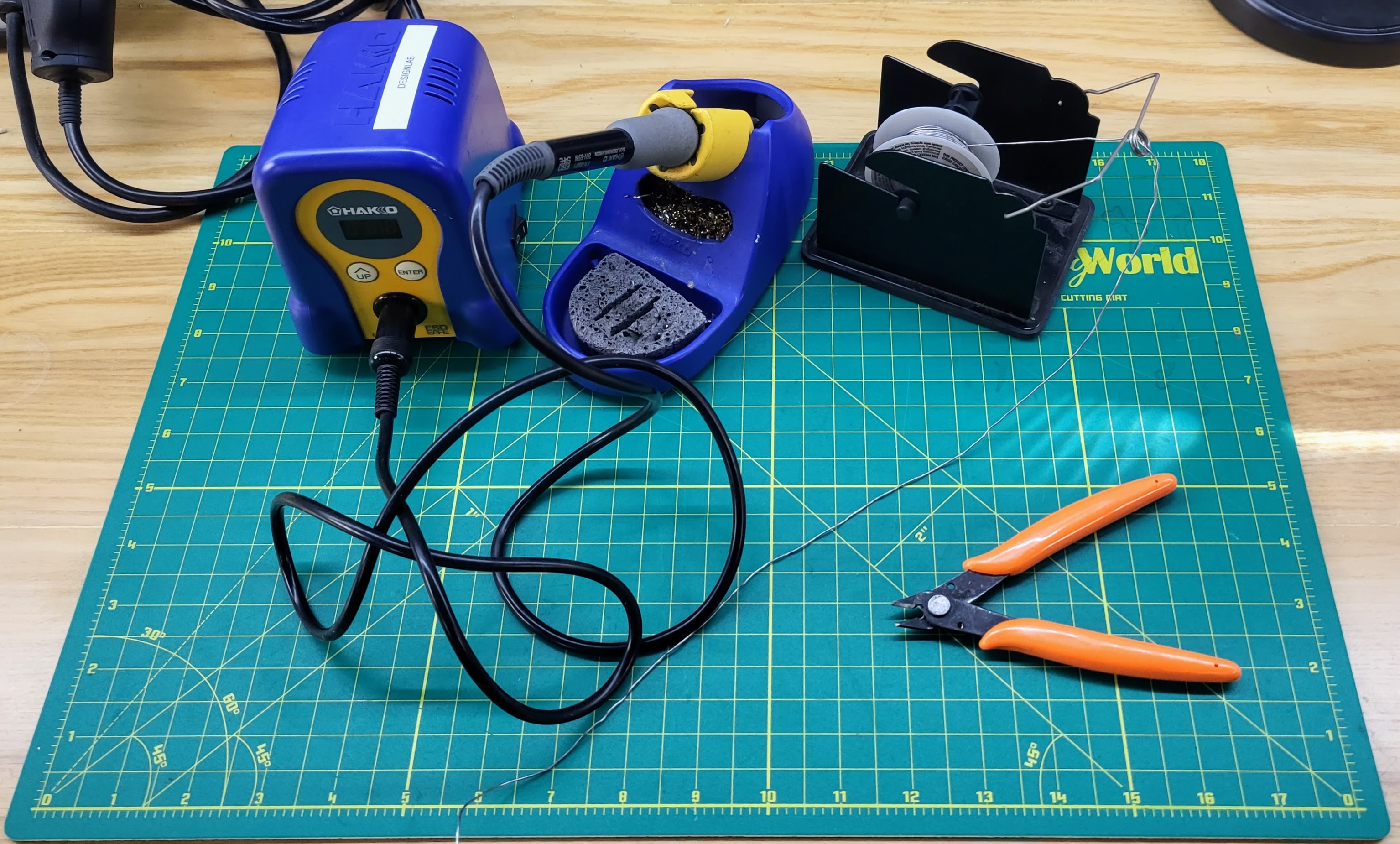
6Recommended tools for the workshop
Provided that you have the PCBA kit and the lamp body that you designed, you only these tools:
- Soldering iron
- USB to USB micro cable
- 3 AA batteries
- Solder
- Wire cutters. We recommend precision diagonal cutters with tapered head
![]()
If you are taking this workshop at the DesignLab, to fabricate your lamp body you may use:
- Laser cutter,
- CNC mill,
- CNC router,
- 3D printers
- Wood shop tools
Anything except for the laser cutter would take more than one session to make, so please reach out in advance to see how we can fabricate your parts. Also, some tools need special training before using.
-
7Drag and drop MicroPython
These instructions were taken directly from Raspberry Pi Microcontroller's Documentation. They are here for convenience, but it is recommended that you check Raspberry Pi's official website first for the most up-to-date information.
- - - - - - - - - - - - - - - - - - - - - - - - - - - - - - - - - - - - - - - - - - - -
Download the correct MicroPython UF2 file for your board:
- Raspberry Pi Pico
- Raspberry Pi Pico W (with urequests and upip preinstalled)
Then go ahead and:
- Push and hold the BOOTSEL button and plug your Pico into the USB port of your Raspberry Pi or other computer. Release the BOOTSEL button after your Pico is connected.
- It will mount as a Mass Storage Device called RPI-RP2.
- Drag and drop the MicroPython UF2 file onto the RPI-RP2 volume. Your Pico will reboot. You are now running MicroPython.
- You can access the REPL via USB Serial.
The Raspberry Pi Pico Python SDK book contains step-by-step instructions for connecting to your Pico and programming it in MicroPython using both the command line and the Thonny IDE.
- - - - - - - - - - - - - - - - - - - - - - - - - - - - - - - - - - - - - - - - - - - -
Once you have Micropython installed in your Raspberry Pi Pico, you may now open Thonny to start coding. Make sure you select your Raspberry Pi Pico (bottom right corner of your Thonny screen).
-
8MicroPython Code
Use Thonny for this code.
from machine import Pin, ADC, Timer import utime import machine, neopixel lighton = 1000 #time in miliseconds that LEDs are on after touching the sensor #colors (values 0-255) red = 10 blue = 0 green = 20 led = 18 # GPIO18 sensor_ADC0 = 26 # GPIO26 neopixelPin = 22 #GPIO22 np = neopixel.NeoPixel(machine.Pin(neopixelPin), 4) def turnOffNeopixel(timer): neopixelControl(0) print("Lights off") #Function for turning on/off Neopixels # 1 = On # 0 = Off def neopixelControl(control): if control: np.fill((red, blue, green)) # Set all pixels to red np.write() # Update the NeoPixel strip np[0] = (255, 255, 255) # set to white, full brightness np[1] = (255, 255, 255) # set to white, full brightness np[2] = (255, 255, 255) # set to white, full brightness np[3] = (255, 255, 255) # set to white, full brightness else: np.fill((0, 0, 0)) # Turn off all pixels np.write() # Update the NeoPixel strip np[0] = (0, 0, 0) # set power off np[1] = (0, 0, 0) # set power off np[2] = (0, 0, 0) # set power off np[3] = (0, 0, 0) # set power off timer = Timer() ADC0 = machine.ADC(sensor_ADC0) led = Pin(led, Pin.OUT) led.on() while True: sensorReading = ADC0.read_u16() print("Sensor State: ", sensorReading) if sensorReading < 60000: print("Sensor detected") neopixelControl(1) timer.init(mode=Timer.ONE_SHOT,period=lighton, callback=turnOffNeopixel) utime.sleep(0.1) -
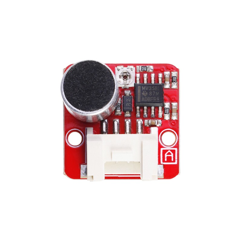
9Grove / Crowtail Sensors and their code
The newest version of the workshop incorporates three Grove connectors that can be used with anything you want! In order to get us started, we will have code here for four inputs. Sound sensor, touch sensor, motion sensor, and button. Choose your favorite! Don't forget to click on the "wiki link" for each one of these to get more information.
You can download custom code for activating the RGB LED's in the Files section here.
https://www.elecrow.com/crowtail-sound-sensor-p-1273.html
![]()
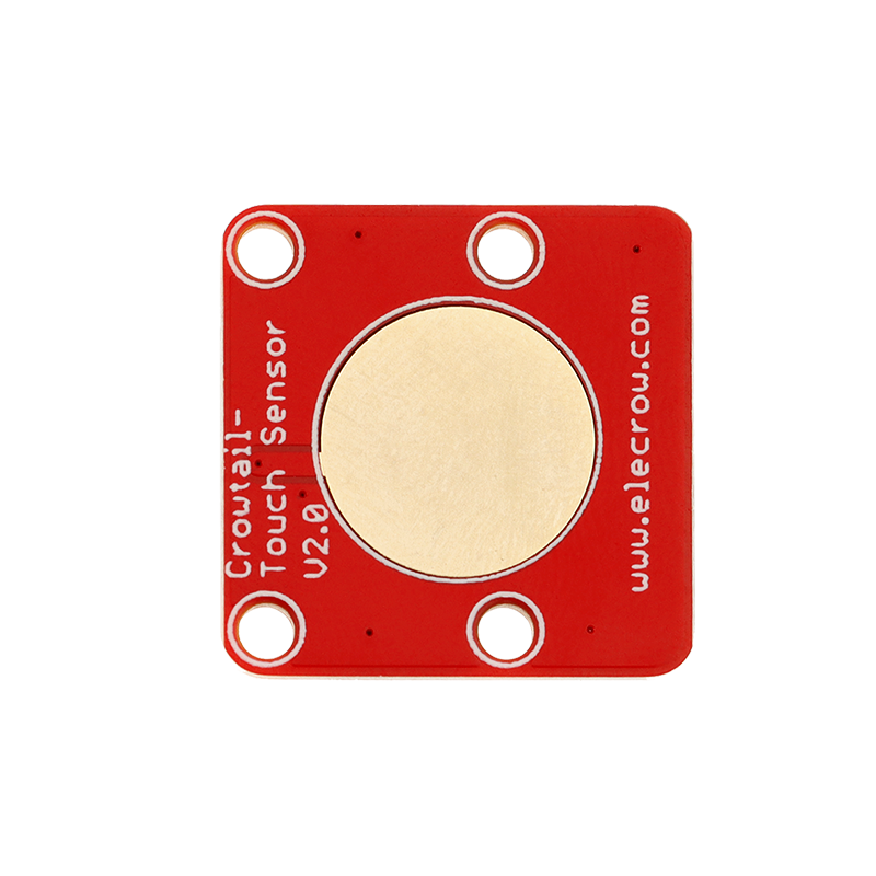
https://www.elecrow.com/crowtail-touch-sensor-p-1230.html
![]()
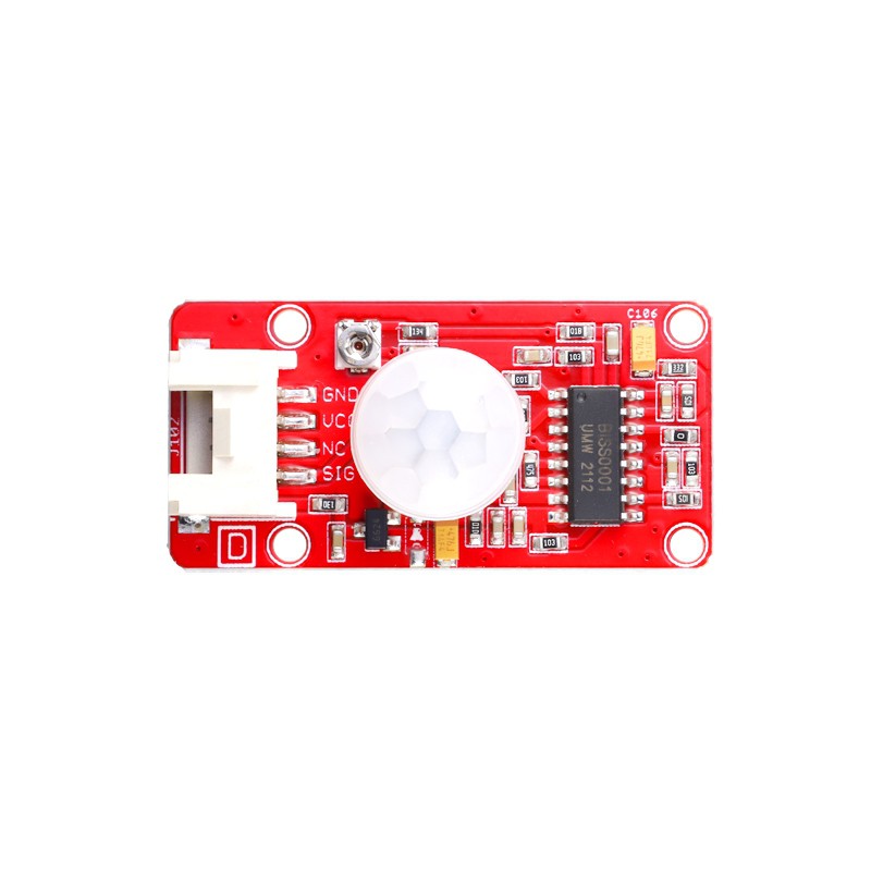
https://www.elecrow.com/crowtail-pir-motion-sensor-p-1518.html
![]()
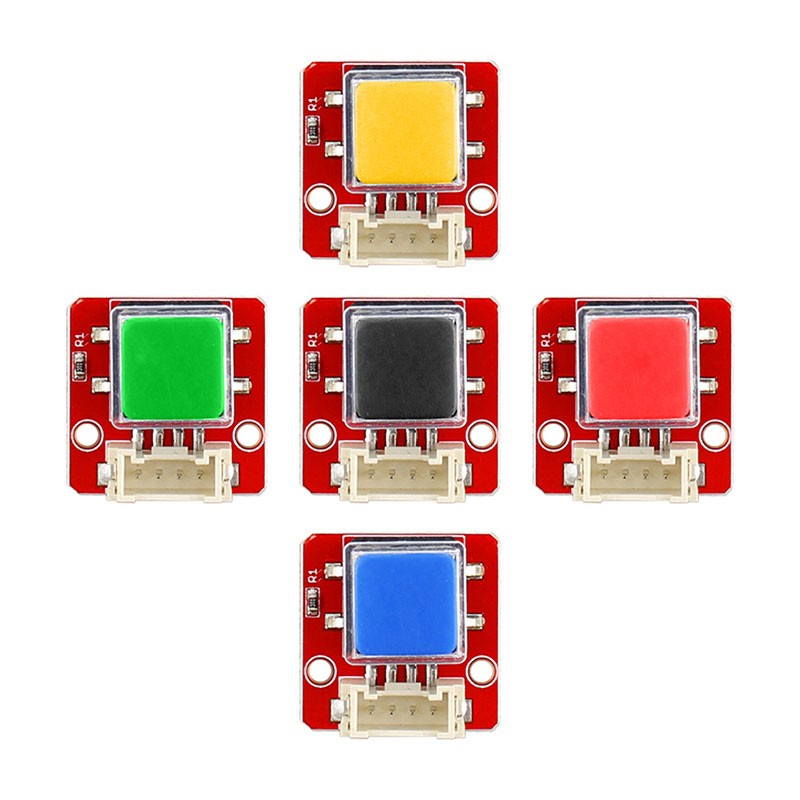
https://www.elecrow.com/crowtailbutton-p-1222.html
![]()
(Images taken from elecrow.com)
-
10Turbocharging your Controller Board!
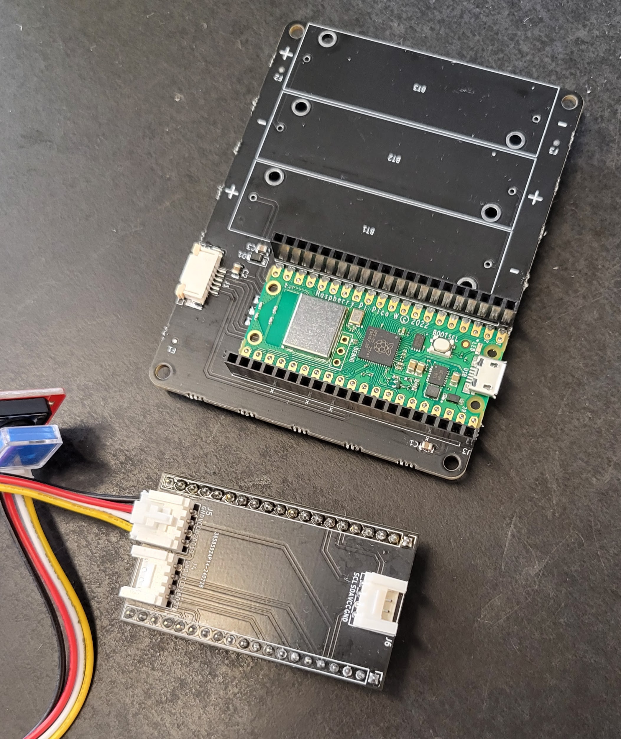
***** THIS ONLY APPLIES FOR LEGACY CONTROLLER BOARDS WITH NO GROVE CONNECTORS TO THE SIDE *******
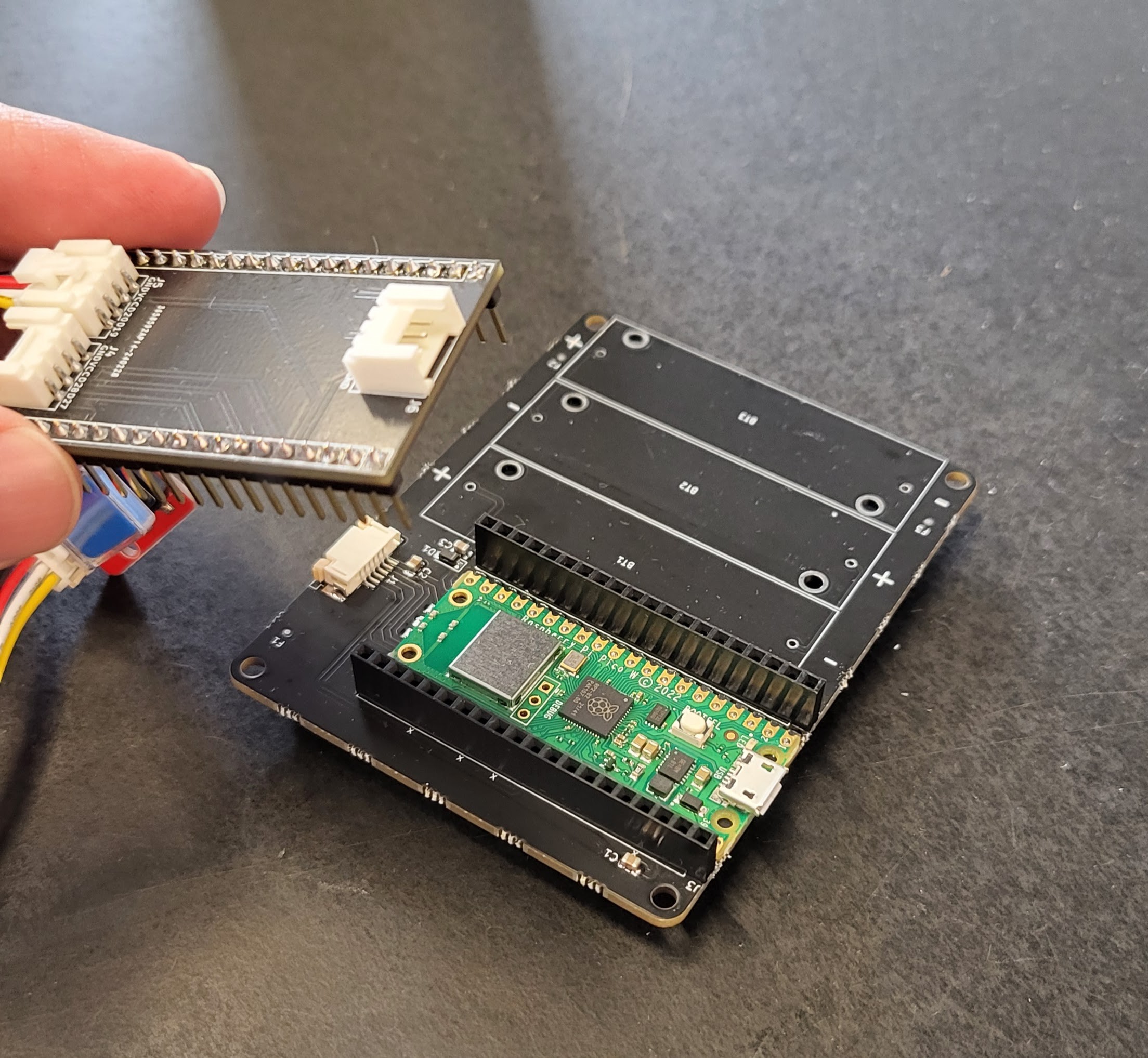
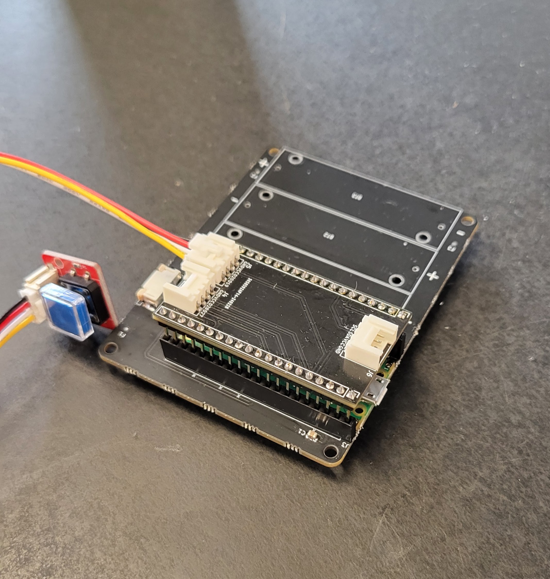
Your controller boards just got more powerful! We created this simple shield that connects up to three grove connectors. They go straight to the Pi Pico so you'll get I2C/ADC, SCL/SDA data transmission.
The photos below show the correct shield orientation.
![]()
![]()
![]()
PCB Lamp Workshop
Components and instructions to create your own touch-activated lamp, and learn about product design, hardware and firmware.

Discussions
Become a Hackaday.io Member
Create an account to leave a comment. Already have an account? Log In.