JP Gleyzes
-
DJI Virtual Flight RC radio interface -3.3V logic-
12/27/2022 at 17:33 • 0 commentsMy previous setup needed a level shifter to accomodate 5V logic of my receiver...
But most of radio today have a "buddy box" mode where they output directly PPM signal from the trainer port.
And these radios are today with 3.3V logic, like the ESP32.
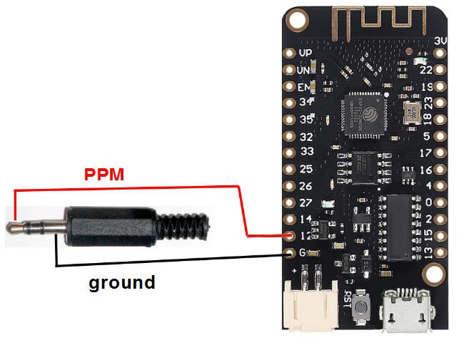
So you can directly connect the PPM jack cable to any IO pin of the ESP32. No more PCB, direct connection :-)
Schematics
Difficult to have something simpler...
![]()
Firmware
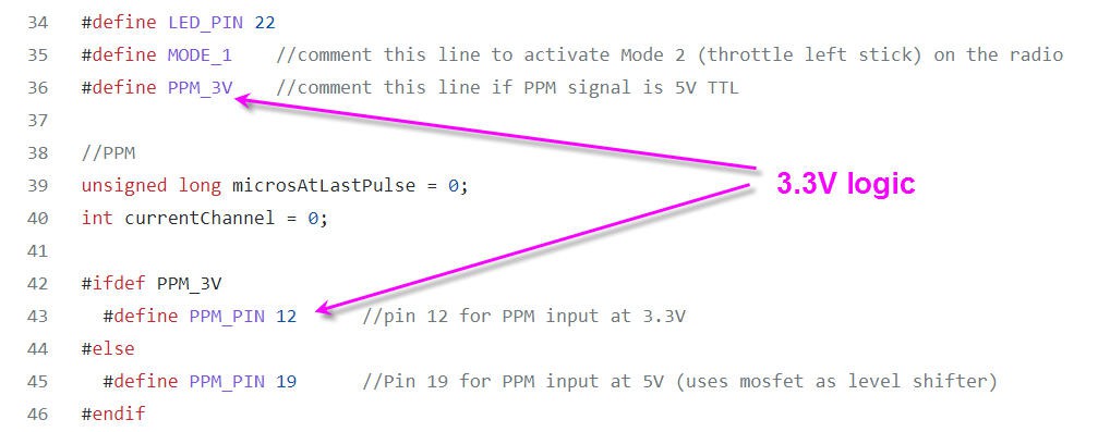
The firmware provided here on my Github is compatible with this 3.3V setup.
Simply be sure to uncomment this line
![]()
-
DJI Virtual Flight RC radio interface
12/24/2022 at 14:00 • 0 commentsPrinciple of operations
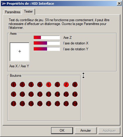
I got a friend's remote controller2 and here is what it gives when connected to a PC
![]()
It's an HID Joystick with X, Y, Z, Rx and Ry "analog sticks" and 7 active buttons.
Here is the law table to map the actions on the remote2 to the corresponding joystick events.
- All sticks output values between +-660
- Right stick
- Left/right: Joystick X axis
- Up/Down: Joystick Y axis
- Left stick
- Left/Right: Joystick Rx axis
- Up/Down: Joystick Z axis
- gimbal wheel: Joystick Ry
- buttons
- C1: Joystick button 1
- Start: Joystick button 2
- home: Joystick button 3
- photo: Joystick button 4
- gimbal 3 states:
- Up: joystick button 5 = 0 and button 6 = 0
- center: Joystick button 5 = 1 and button 6 = 0
- Down: Joystick button 5 = 0 and button 6 = 1
- Mode Fly:
- Normal: Joystick button 7 = 0 and button 8 = 1
- Sport: Joystick button 7 = 0 and button 8 = 0
- Manual: Joystick button 7 = 1 and button 8 = 0
This being known it is easy to reproduce a Bluetooth Low Energy Joystick!
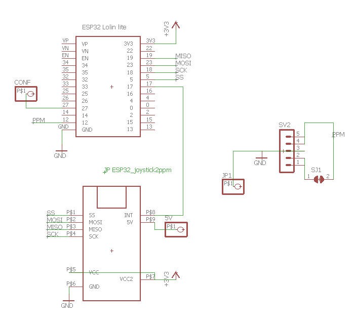
Schematics
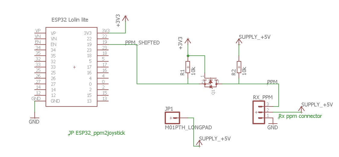
Once again the heart of the system is an ESP32 MCU. The radio receiver or the trainer port output of my radio being 5V devices, I needed a level shifter to accomodate with the 3.3V IO of the ESP32.
And that's it for the schematics: one single pin used as input for the PPM train and the rest over the air via BLE!
![]()
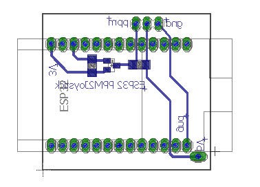
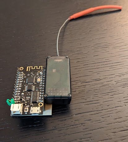
PCB
As you may imagine the PCB is also very simple. My receiver is simply put on the side of the ESP32
![]()
![]()
The board and the receiver are powered by a 5V powerbank and no other connection is needed!
Firmware
Most of the difficulty of this project was not in the hardware side but rather in the software one.
It was really simple to emulate a BLE gamepad, but much more difficult to find the right combination of channels to be accepted by the DJI Virtual Flight. So after a lot of trial and errors I succeeded (see above) !
The code is mostly using the excellent LemingDev BLEgamepad library.
I have only added an interrupt routine to decommutate the PPM train. Only a few lines of code:
void IRAM_ATTR ppmISR() {
  // Remember the current micros() and calculate the time since the last pulseReceived()
  unsigned long previousMicros = microsAtLastPulse;
  microsAtLastPulse = micros();
  unsigned long pulseDuration = microsAtLastPulse - previousMicros;

  if (pulseDuration < MIN_TIME)
  {
    microsAtLastPulse = previousMicros; //cancel the pulse
  }
  else if (pulseDuration > BLANK_TIME)
  {
    currentChannel = 0; // Blank detected: restart from channel 1
    digitalWrite (LED_PIN, !digitalRead(LED_PIN));
  }
  else
  {
    // Store times between pulses as channel values
    if (currentChannel < NB_CHANNELS)
    {
      if ((pulseDuration > 900) && (pulseDuration < 2500))
      {
        rawValues[currentChannel] = pulseDuration;
      }
    }
    currentChannel++ ;
  }
}
The rawValues of the Tx are stored in microsecond reprensenting the duration of each pulse.
then the conversion into gamepad events is also straightforward:
       //bleGamepad.press(BUTTON_1); //C1 button
      //bleGamepad.press(BUTTON_2); //Sart button
      //bleGamepad.press(BUTTON_3); //Pause/home button
      //bleGamepad.press(BUTTON_4); //photo button
      //bleGamepad.press(BUTTON_5); //gimbal Up
      //bleGamepad.press(BUTTON_6); //gimbal Down. And buttons 5 and 6 released = gimbal center
      //bleGamepad.pressHome(); //exit App releaseHome();
      if ((rawValues[5] - 1500) > 250) //trainer button toggle
      {
        bleGamepad.press(BUTTON_7);     //toggle Manual to S
      }
      else bleGamepad.release(BUTTON_7);
      //map(value, fromLow, fromHigh, toLow, toHigh)
      bleGamepad.setX(map(rawValues[3],1000, 2000, -660, 660)); //Right Stick horizontal
#ifdef MODE_1
      bleGamepad.setY(-map(rawValues[2],1000, 2000, -660, 660));  //Right Stick vertical
      bleGamepad.setZ(map(rawValues[1],1000, 2000, -660, 660));   //Left Stick vertical
#else
      bleGamepad.setY(map(rawValues[2],1000, 2000, -660, 660));
      bleGamepad.setZ(-map(rawValues[1],1000, 2000, -660, 660));
#endif
      bleGamepad.setRX(map(rawValues[0],1000, 2000, -660, 660));  //Left Stick horizontal
      bleGamepad.setRY(-map(rawValues[4],1000, 2000, -660, 660)); //gimbal on 3 states switch

      bleGamepad.sendReport();
A you can see I can use:
- the sticks to control the drone
- channel 6 as a momentary switch to toggle Manual to Sport mode
- and the gimbal motion on a three state switch of the radio on channel 5
Source code is on my Github page here : https://github.com/f2knpw/ESP32_DJI_VirtualFlight_RC_radio_interface
-
ESP32 Joystick2PPM board V2
12/18/2022 at 17:01 • 4 commentsPrinciple of operations
Like the V1 board a PPM frame is generated by the MCU.
I have choosen an ESP32 board for that (more modern than the old PIC18F4550).
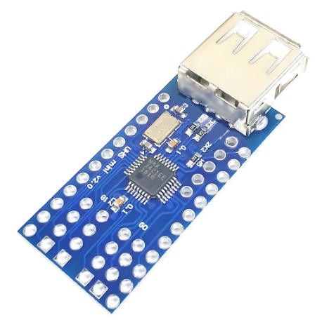
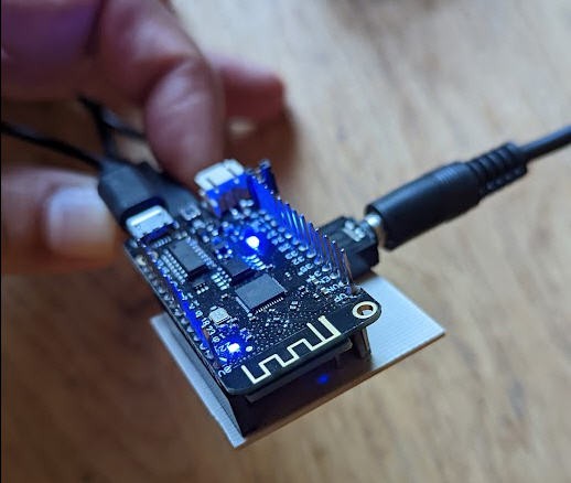
As this MCU does not have an USB interface, I have connected it to a mini USB host shield based on the MAX3421 chip
![]()
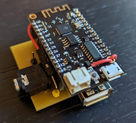
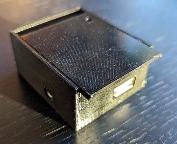
The ESP32 lolin Lite board is mounted in "Mezzanine" above this shield, the result is a quite compact device that can be powered by a USB powerbank.
![]()
It has a USB A female port to connect the joystick and a Jack female port to connect to the radio's trainer port.
All this can be hidden into a 3D printed case which is available on Thingiverse.
![]()
Configuring the board
As this new setup works without Android App, I had to find a way to introduce a kind of Man Machine Interface to configure the board.
I have simply used the ESP32 WifiManager library capabilities to do this.
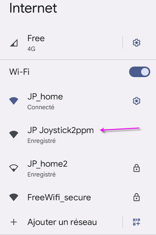
So if you boot the board (or reset it with the reset button) while touching the small pin close to the jack connector, then the ESP32 exposes a Wifi hotspot on which you can connect any smartphone (or PC)
![]()
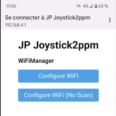
Connecting to it will automatically open a configuration window
![]()
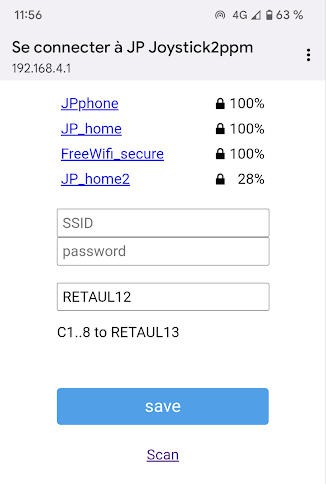
You then have to choose an exisitng wifi network for which you have the credentials, enter them into the form
![]()
Then you can change the magic sentence "RETAUL13" to configure the 8 channels of your board.
You can affect any stick, any button( 1 to 8) and hat to any channel. The syntax is simple :
REATUL12 meens:
- Channel 1 of PPM will be affected to Rudder
- Channel 2 of PPM will be affected to Elevons
- Channel 3 of PPM will be affected to Throttle
- Channel 4 of PPM will be affected to Ailerons
- Channel 5 of PPM will be affected to Up/down button of the hat stick
- Channel 6 of PPM will be affected to Left/right button of the hat stick
- Channel 7 of PPM will be affected to button 1
- Channel 8 of PPM will be affected to button 3
And that's it, click on save and wifi will disapper while the board reboots and outputs the PPM signal.
So if you want to change this setting you can for intance write : TRAE123L
This will configure this way:
- Ch1 to Throttle
- Ch2 to Rudder
- Ch3 to Ailerons
- Ch4 to Elevons
- Ch5 to button1
- Ch6 to button2
- Ch7 to button3
- Ch8 to Left/right hat
Schematics
Well nothing complex here. Just connect the ESP32 board to the USB Host shield...
![]()
SImply note that the 5V supply for the shield is pick up after the USB plug of the EPS32 board. (red wire on the photo). SO a single USB power bank will power both the ESP32 and the USB shield.
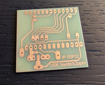
PCB
A quite simple PCB has been home made.
![]()
leading to a very compact form factor
![]()
You can download the eagle files here
-
Joystick2PPM board V1
12/17/2022 at 21:06 • 0 commentsPrinciple of operations
Most RC radio accept PPM signal as input on their trainer port.
PPM signal is a Pulse Position Modulation signal. When applied to RC rdaio it simply consist in adding the 8 channels of the servos into a single frame.
Each frame has 20ms length
![]()
The channels are simply added one after the other whithin this 20 ms frame.
A pulse (0.5 ms) is generated to start a new channel. The duration from the start of the pulse to the next one is equal to the servo value (1 ms to 2 ms).
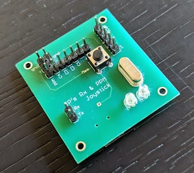
A little board has been made to generate the PPM train.
It is a USB HID device and can be connected to any USB host plug. So this board may work connected to a PC but also connected to the USB host of an Android phone.
![]()
The board then communicates with the host via a custom HID protocol embedded into the firmware.
The other side (host) of the protocol is handled by the android App : JG Joystick2PPM
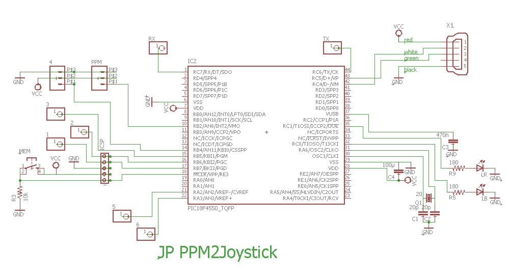
Schematics
The heart of the system is a PIC18F4550 microcontroller.
![]()
The schematics is quite simple and implements the basic circuitry of a HID device proposed by Microchip.
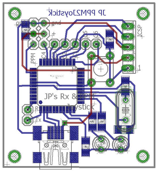
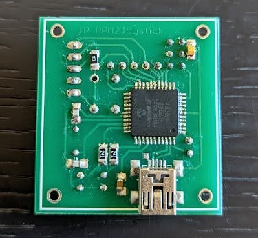
PCB
The PCB has been manufactured and all the eagle files are available if you want to reproduce it.
![]()
![]()
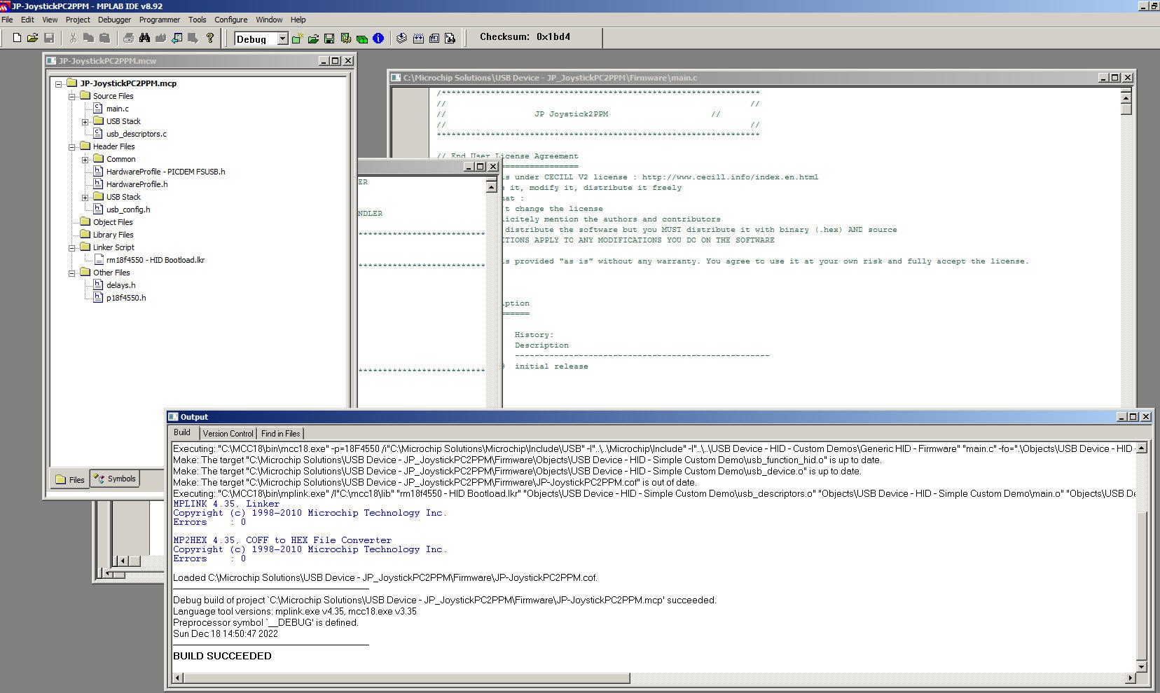
Firmware
The board is programmed in C under MPLAB-IDE.
![]()
FIrmware is avalable here including .hex file and all source code
Please note that this code is provided under the Cecill V2 open source licence. Details regarding this licence are available here .
A poor man's FPV journey
If you want to enter FPV world in a cheap way, read these pages !