-
1Step 1: verify that everything works properly
NOTE: none of the following steps require a power supply connected to any of the boards, but in case you want to do so, connect the power supply to the board BEFORE plugging it to your PC and opening the port, as this may cause a short circuit on your PC and/or partially burn the board (we went through this twice, so please don't)
Plug the Arduino board and open Arduino IDE (https://www.arduino.cc/), then go to Tools, then Port, and check that the name of the port you connected the Arduino to includes "(arduino)" in its name, as the python program won't recognize it otherwise. Then, upload the blink sketch from the Basics examples folder. Verify that it was succesfully uploaded and that the Arduino board's LED blinks as it should.
Then, upload the PhysicalPixel sketch from the Communication examples folder to the Arduino board. You can also find this sketch in the files of this proyect. Check that it was uploaded properly and disconnect the Arduino board.
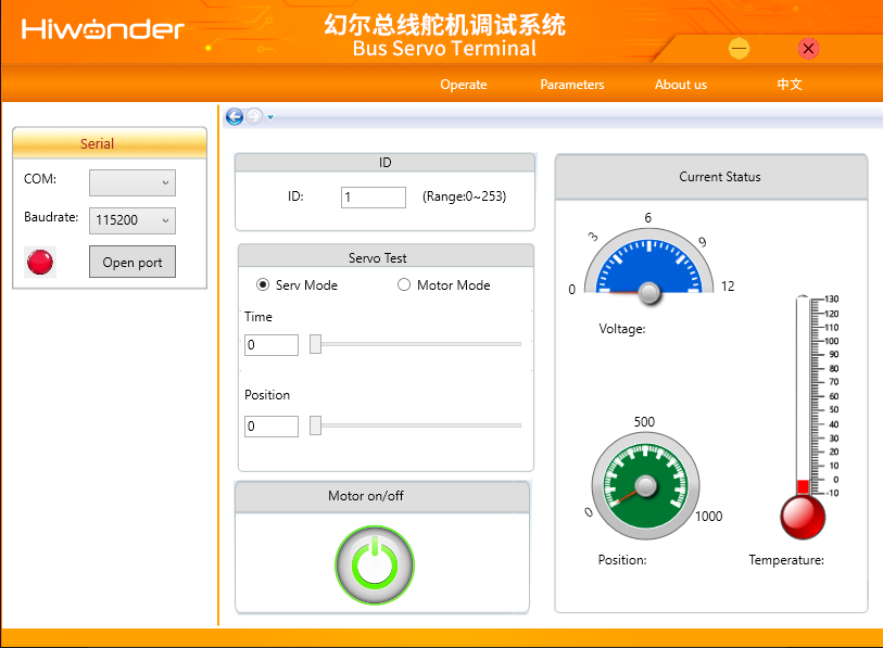
Now, install the Bus Servo Terminal V1.7 on your PC from the Lewansoul LX-16A documentation (http://bit.ly/2rJshh6 in the LX-16A folder) and plug in the bus servo controller with at least one servo connected to it to your PC. Run the Bus Servo Terminal program, you should see something like this:
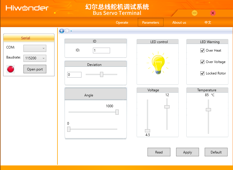
Click on COM and open the port you connected the controller onto and click Open port. If the servo works properly, the servo's LED should turn on and you should be able to see the servo's ID and the current position of the servo in current status. Without a power supply, the servo won't move if you change the position in servo test, but that's not necessary as we will do that in the python program. Now, go to parameters. You should see something like this:
Change the servo's ID to the one you'll use in the code later (the ID's in the code are 4 and 6 for left and right servos respectively, but you can edit that in the code later), then click apply. Once you are done, you can click on Close port, connect the second servo and repeat, and make sure to asign a different ID from the precious one. Even if you don't use the ID's from the code, you still need to asign different ID's to each servo to use them at the same time. Once you are done, click on Close port again, then disconnect everything and close the program.
-
2Step 2: build your own funny robot
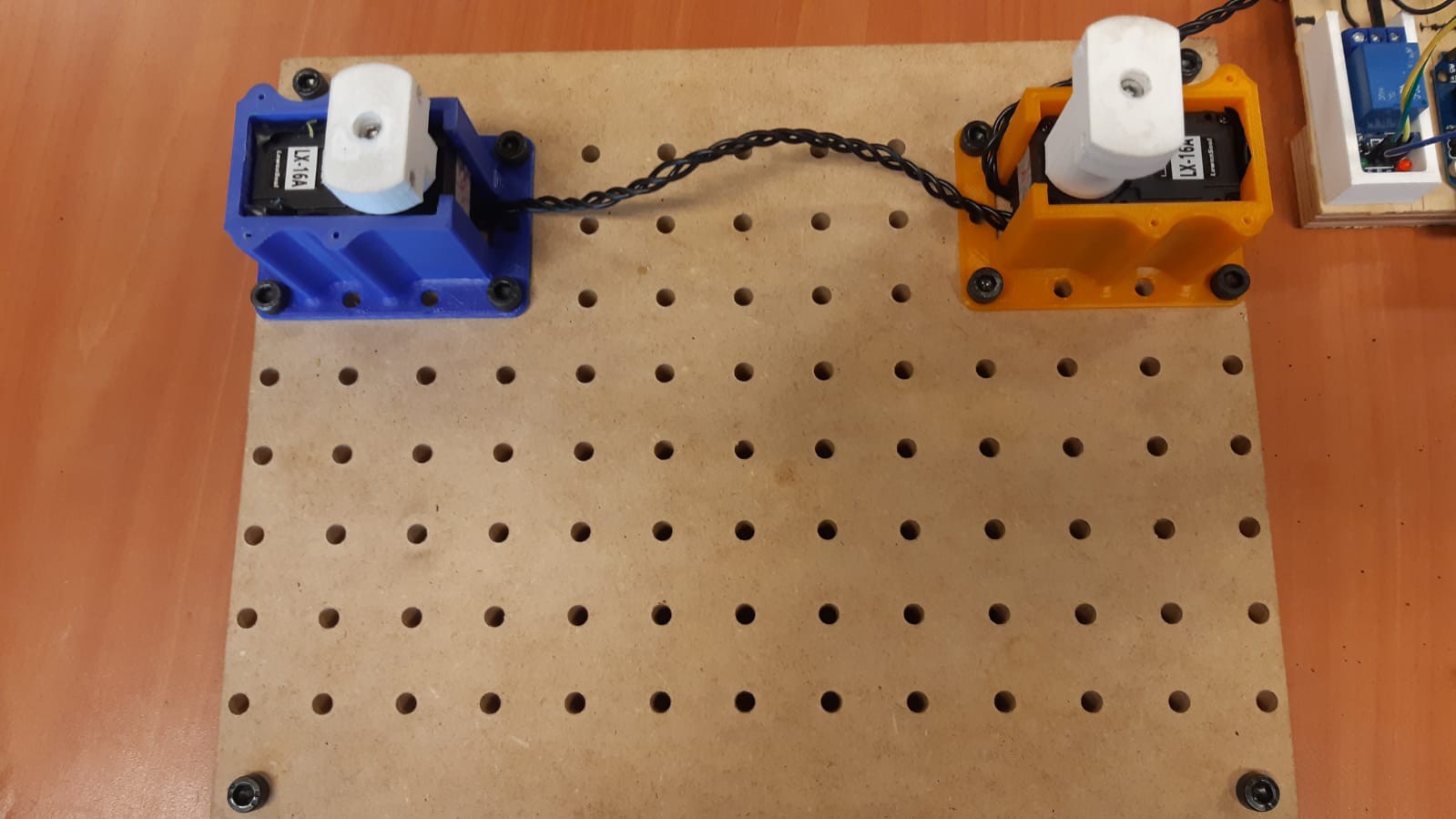
First of all, fix the servos bases to the base using the M5 screws and nuts like so. In case you are using the extra screws as support, place the larger ones on the corners as seen on the following image. If instead you are using anything else as support (like bottle caps), glue them underneath where the extra screws would be:
![]()
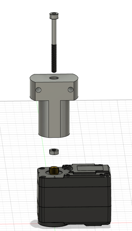
Then, on the servos, screw the shoulders to each servo, using the M3 screws with different lengths and a nut for each, placing the nut between the servo and the bottom of the shoulder.
Then, connect the servos to the controller. The servos can be connected serially instead of using one port for each servo, by using the second port underneath itself, which in this case allows more movement for the controller board while assembling everything.
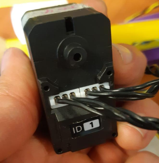
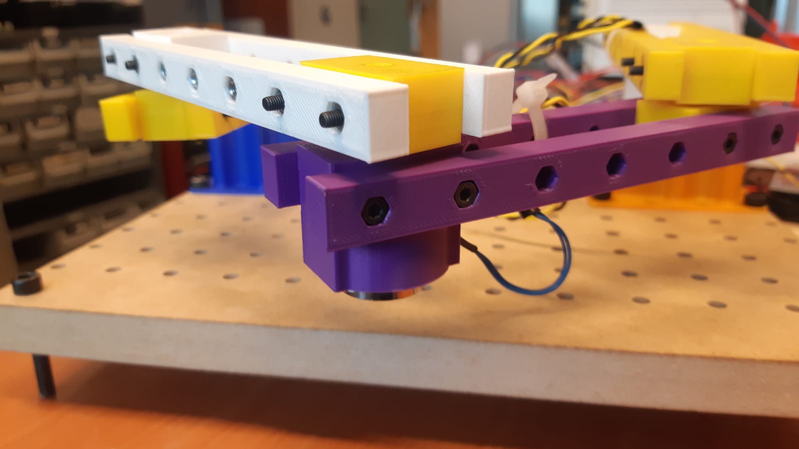
Now, place them on the bases, and make sure the shoulders are not fully tightened, so you can adjust them later. Also, write down the ID's and the positions of the servos from BEHIND, so you can edit them in the code if necessary.
![]()
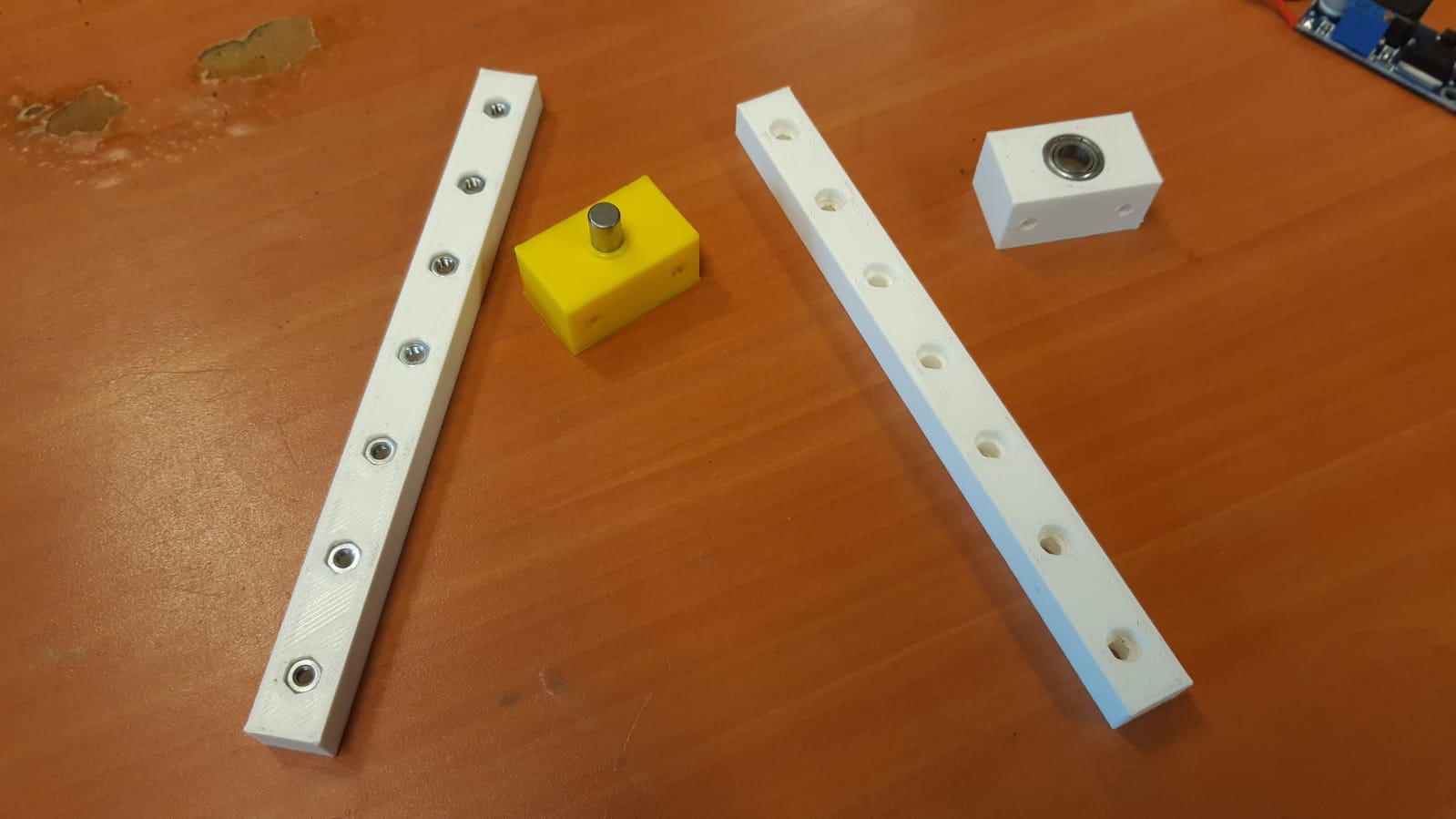
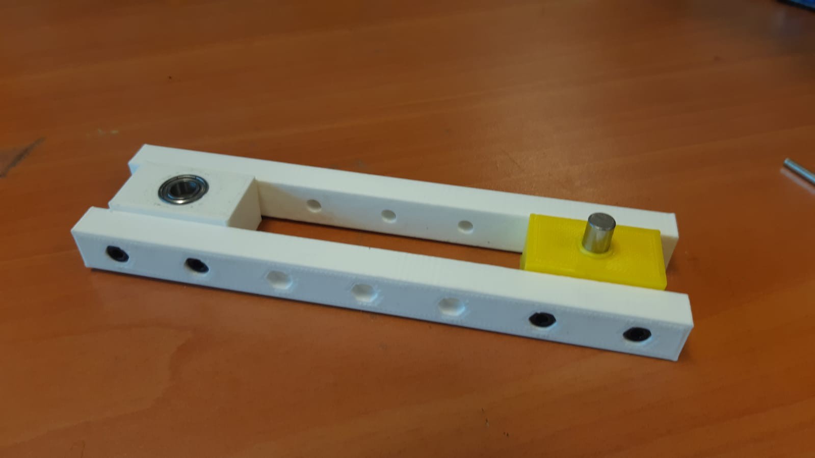
Then to the arms: take 2 arms' halves, a bearing, a pin, an elbow for each, and at least 4 nuts, and assemble them like so. Make sure that everything fits tight, especially the pin. Note that you only need to put nuts on one of the arms' halves, and if you are planning to use the minimum amount of nuts, place 2 nuts on each end of one of one half of each arm:
![]()
With this, put everything together using the M3 screws, 2 for each end:
![]()
This will be the basic assembly for the arms, but put this one aside for now.
Now, repeat this two more times, but only using one pin elbow for each arm, and screw these to the shoulders. Make sure the pin points downwards on the higher arm, and upwards on the lower arm like so:
![]()
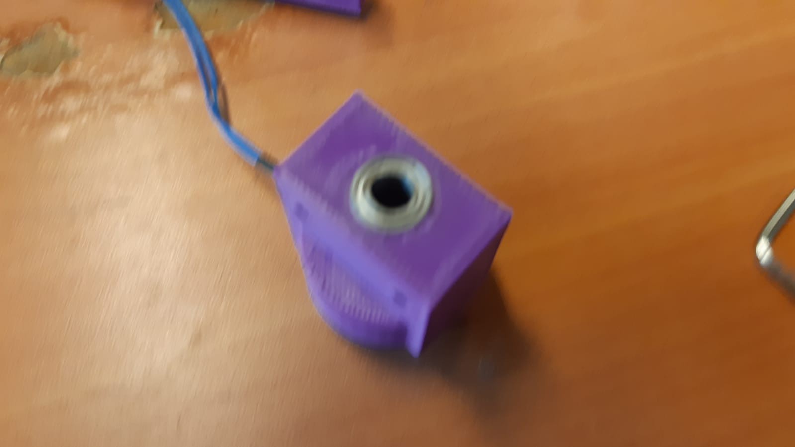
Now, assemble the electromagnet elbow. Place the electromagnet inside first, aligning its cables, then screw it to the elbow and put the bearing on top.
![]()
![]()
![]()
Repeat the arm assembly with the remaining bearing elbow and the electromagnet. Take the remaining two arms and put them on each side, and make sure the pins don't slide inside their elbows while assembling:![]()
Finally, connect the ends of each arm, and make sure that the pin doesn't slide.
![]()
-
3Step 3: the electronics
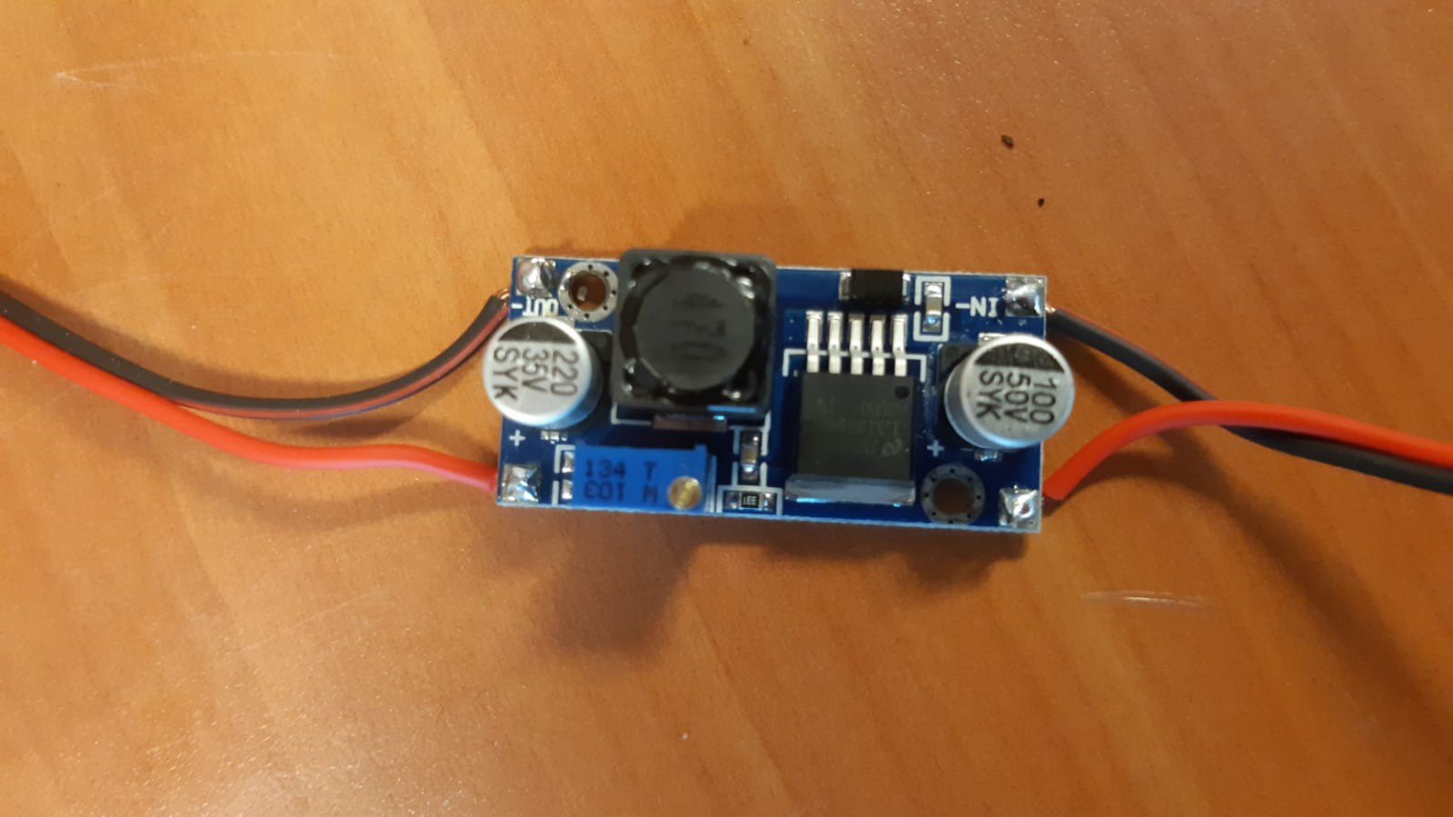
First of all, connect the step down to the power supply, turn it on, and adjust the output voltage to 6V by tightening the golden screw on top of the step down, while checking with a multimeter.
![]()
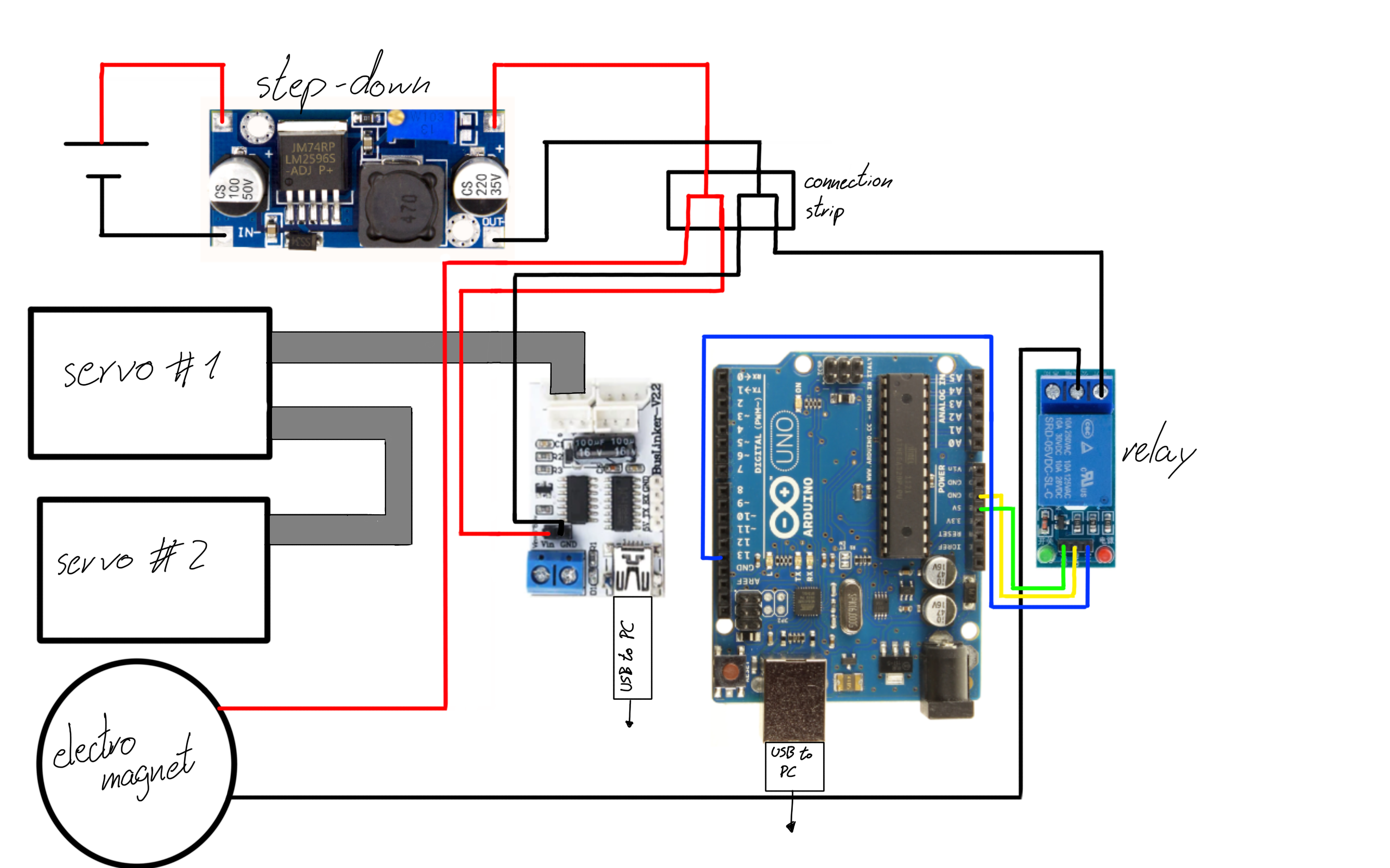
Now, turn off the power supply and proceed with the connections as follows, but DO NOT connect the USB cables to your PC yet.
![]()
Note that you can also use 2 6V batteries instead of a power source and a step down, by replacing the connections on the strip: use one battery for the servo controller alone, and the other one for the relay and electromagnet circuit.At this point you can turn on the power source to verify that the boards and the servos turn on, and nothing starts burning itself, just in case.
-
4Step 4: the code
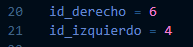
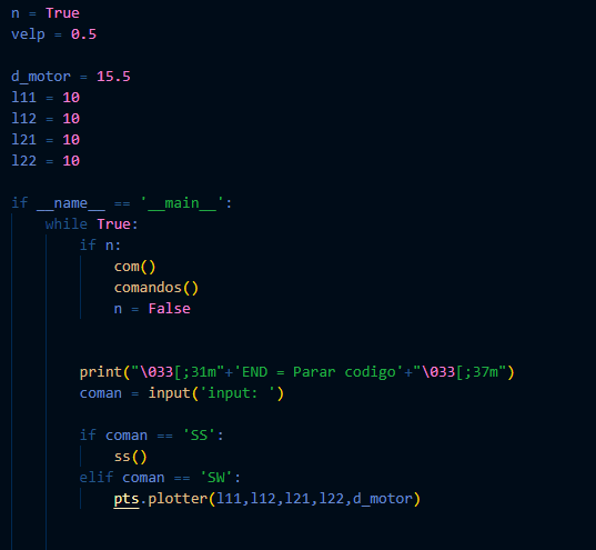
Download and open the code folder on your code editor software of your preference (e.g. vs code) and open the Scara.py file. Then, check that the ID's in the Scara.py file match the ID's that you set up on the servos. These ID's are on the firsts lines of code:
The default ID's on the code are 4 for the left servo (id_derecho) and 6 for the right one (id_izquierdo). If you used different ID's or in different order, edit them directly on the code.
Another parameter you might want to edit now is the speed of the servos. In the lasts lines of code before the main loop there's the velp parameter, which represents the steps per milisecond on both servos. It's set by default on 0.5, which is not particularly slow, but raising it to 0.7 is fast enough for the robot to not to break, and 0.2 is slow enough to give you enough time to disconnect anything.![]()
You can also change the default dimensions on the code, noted by l11,l12,,l21,l22 and d_motor, which represent right humerus, right forearm, left humerus, left forearm and the distance between the centers of the servos, all in cm.
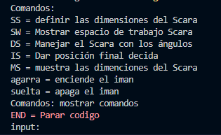
Now, turn on the power supply, and ONLY THEN connect the boards to your PC and run the Scara.py file. If everything works properly, the code should run without errors and should ask for commands in the console.
![]()
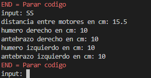
The first command, "SS", allows you to change the dimensions in cm the code uses for the calculation of the task-space and the angles it sends to the servos. Once typed, the program will ask for distance between servos, length of right humerus, right forearm, left humerus and right forearm in that order. This is meant to adapt the code once you reassembly the robot, which is its main purpose.
![]()
The next command, "SW", will show you 2 plots: the c-space, that is, the angles in degrees the motors can move to without tearing itself apart, and the task-space, which are the positions the robot can reach.
![]()
The next one, "DS", controls the servos by directly sending them the angles, measured in degrees and from the line that connects the servos, to the right and the left servos in that order. If you send angles that would tear apart the robot, the code won't send them and will ask for commands again.
![]()
With this, now you can send 90° and 90°, wait for the servos to move, and tighten the bolts on the shoulders so that the arms are straight an parallel to each other.
The next command, "IS", allows you to click points directly on the task-space plot in any order, and then will send them to the servos in that order, going to each point and waiting 3 seconds before going to the next point.
![]()
The next 2 commands, "agarra" and "suelta", turn on an off the electromagnet respectively. Finally, "Comandos" prints the previous commands with their explanation in spanish, and "END" stops the code. Make sure to type END every time you stop using the robot and before disconnecting the USB cables, since it closes the serial communication with the boards, and also (at least in vscode) it won't allow you to run anything else until you do.
And that's it! you're now able to control the robot.
Modular 5-bar robot
A 5-bar robot with variable geometry to dinamically ilustrate changes in the spacework of the robot based on its dimensions


Discussions
Become a Hackaday.io Member
Create an account to leave a comment. Already have an account? Log In.