-
1Print and gather parts
Read the rest of the instructions before printing so you have an idea which parts may need adjusting for tolerances.
Print files on Printables.com or just export from the FreeCAD source file.
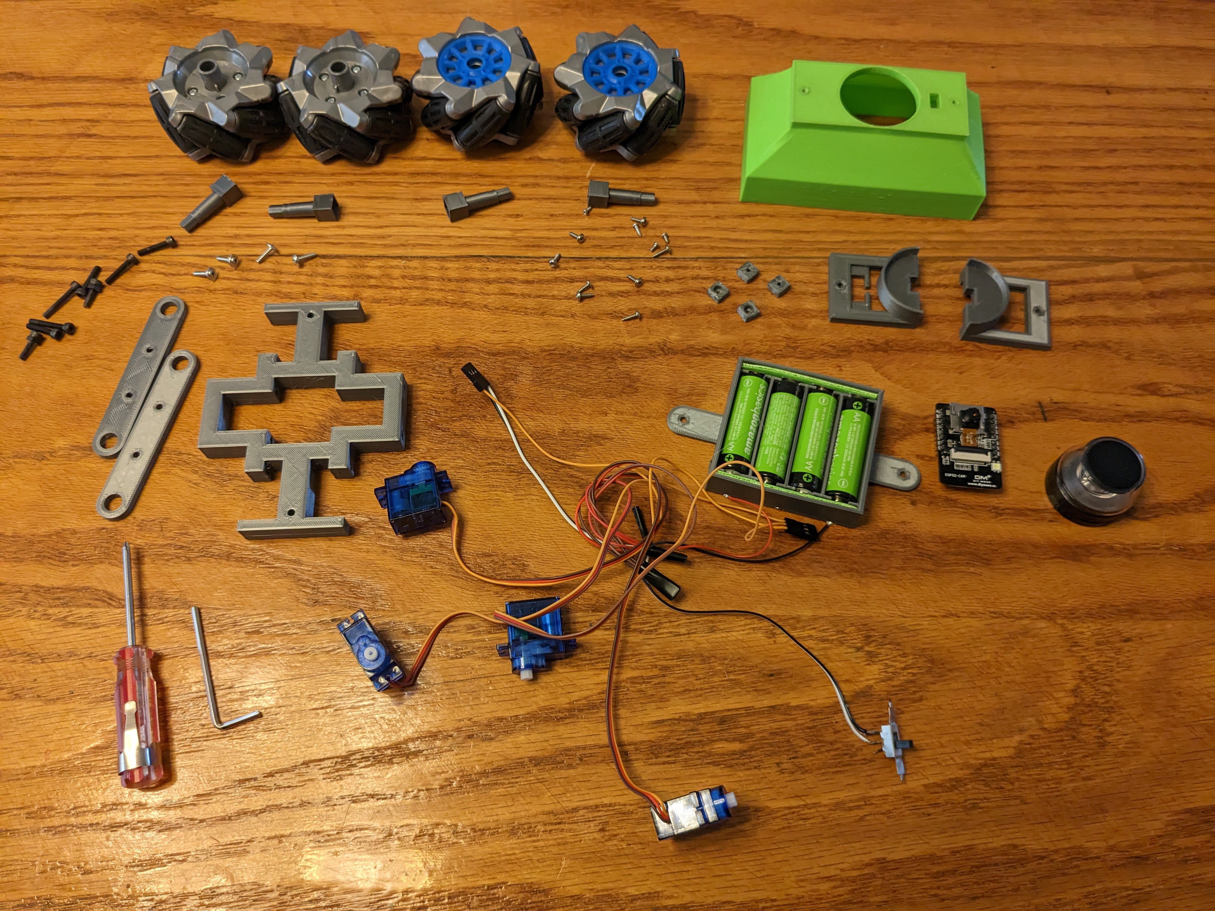
Print the following:
- 1x Battery holder
- 1x Cam holder A
- 1x Cam holder B
- 1x Chasis
- 4x servo shaft square
- 4x wheel shaft coupling
- 1x top cover
- 2x wheel holder bar
I printed most in PETG, except the top cover is ABS.
![]()
-
2Assembly: Mount the servos
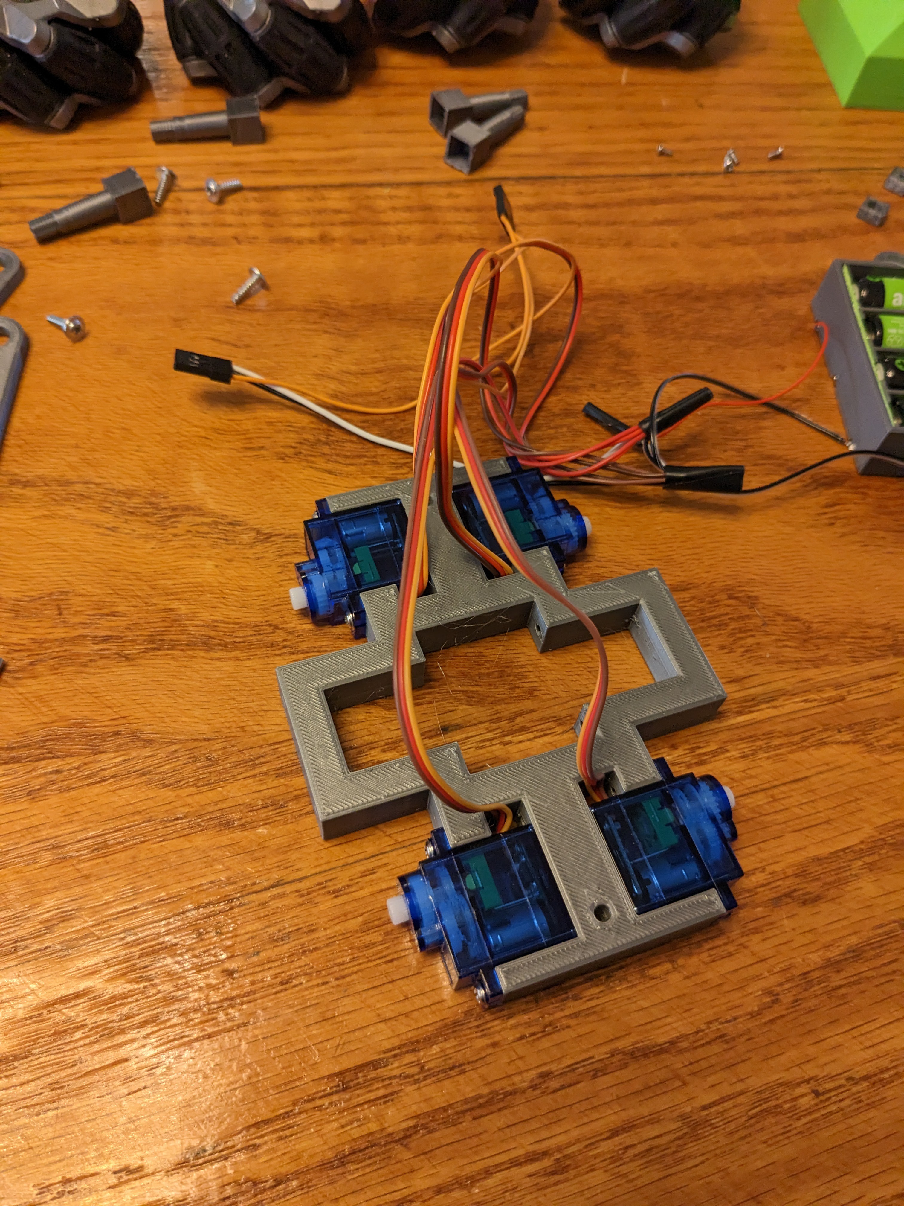
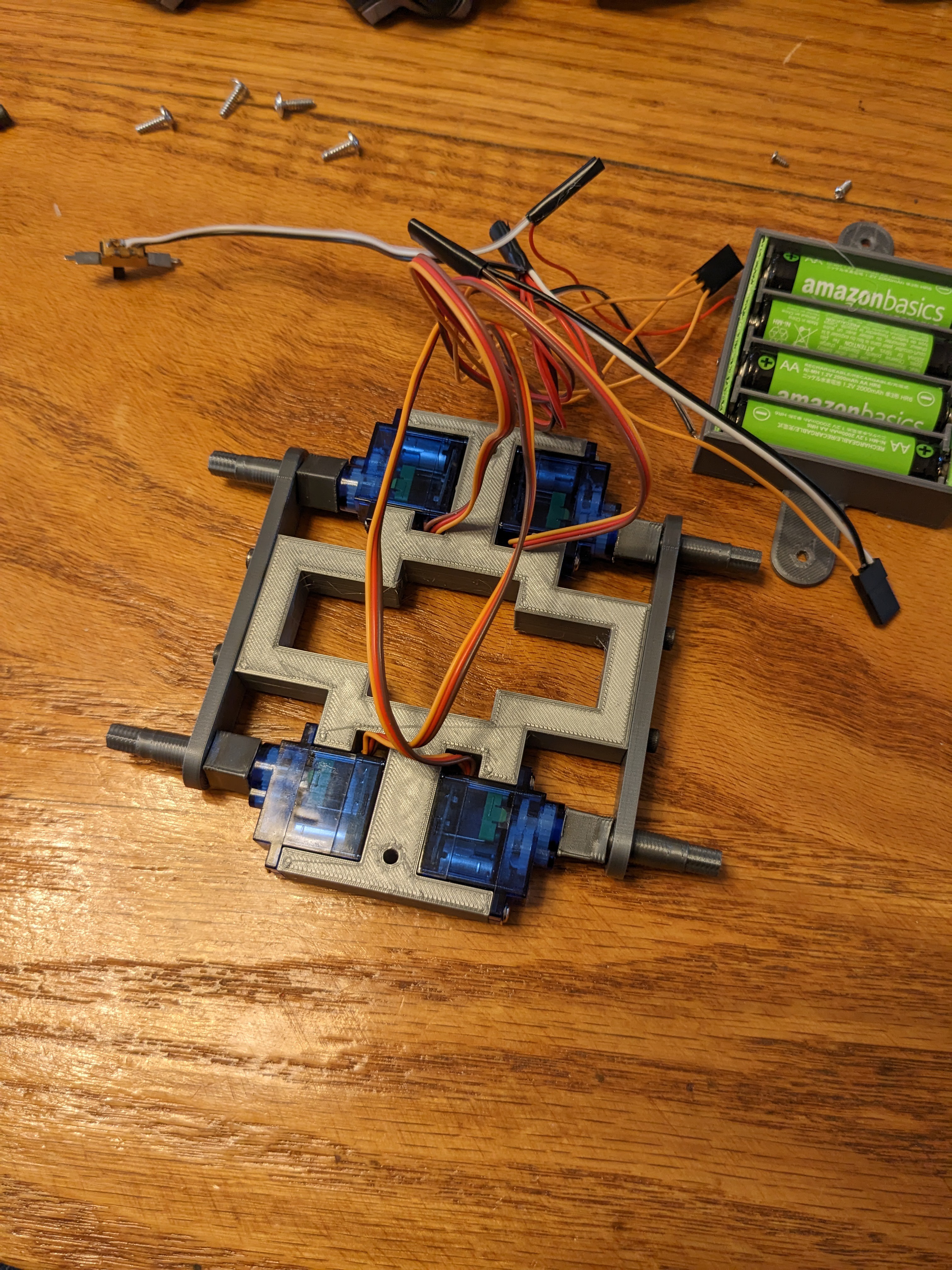
Mount the servos like so. Note the wire paths.
![]()
Hopefully they came with mounting screws. The screws must be a tight fit in the holes.
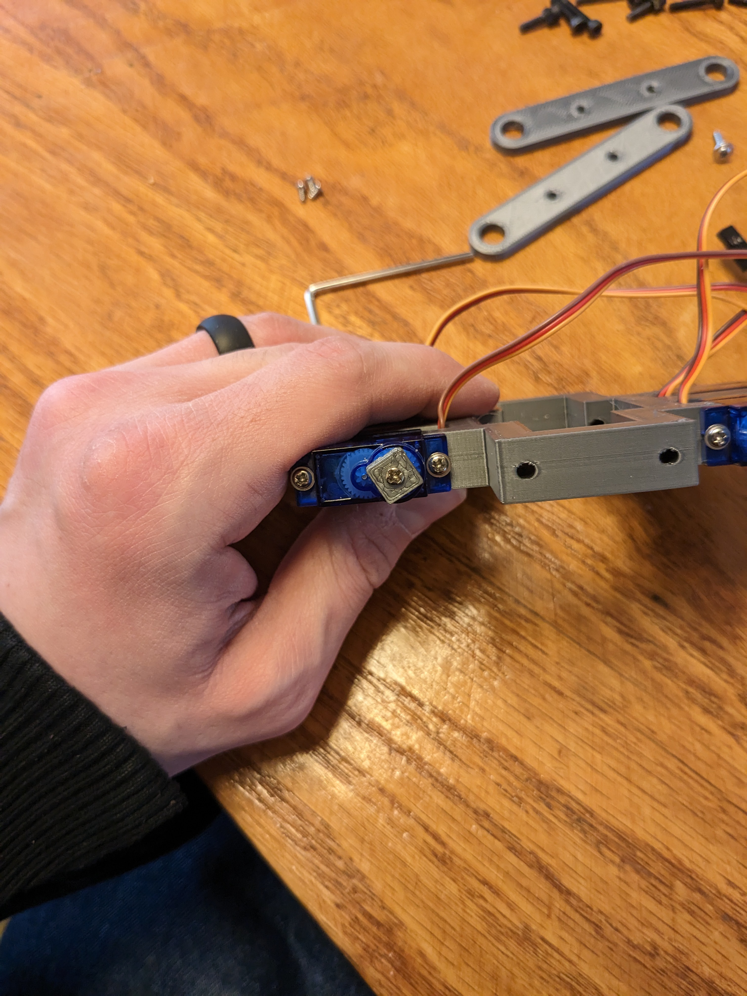
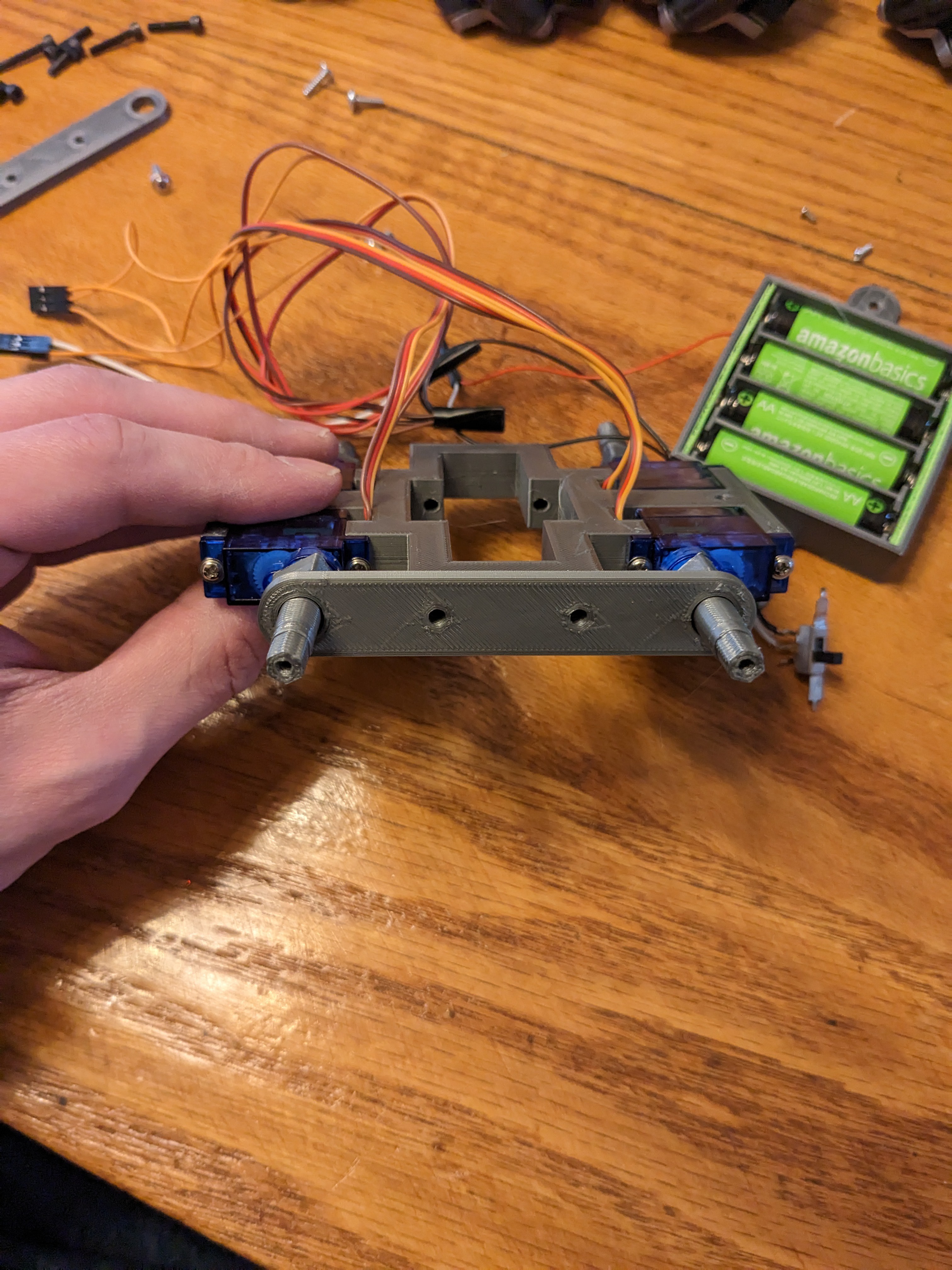
Put the servo shaft squares on the servo shafts. They should be a tight fit. Hold them in place with a shaft screw.
![]()
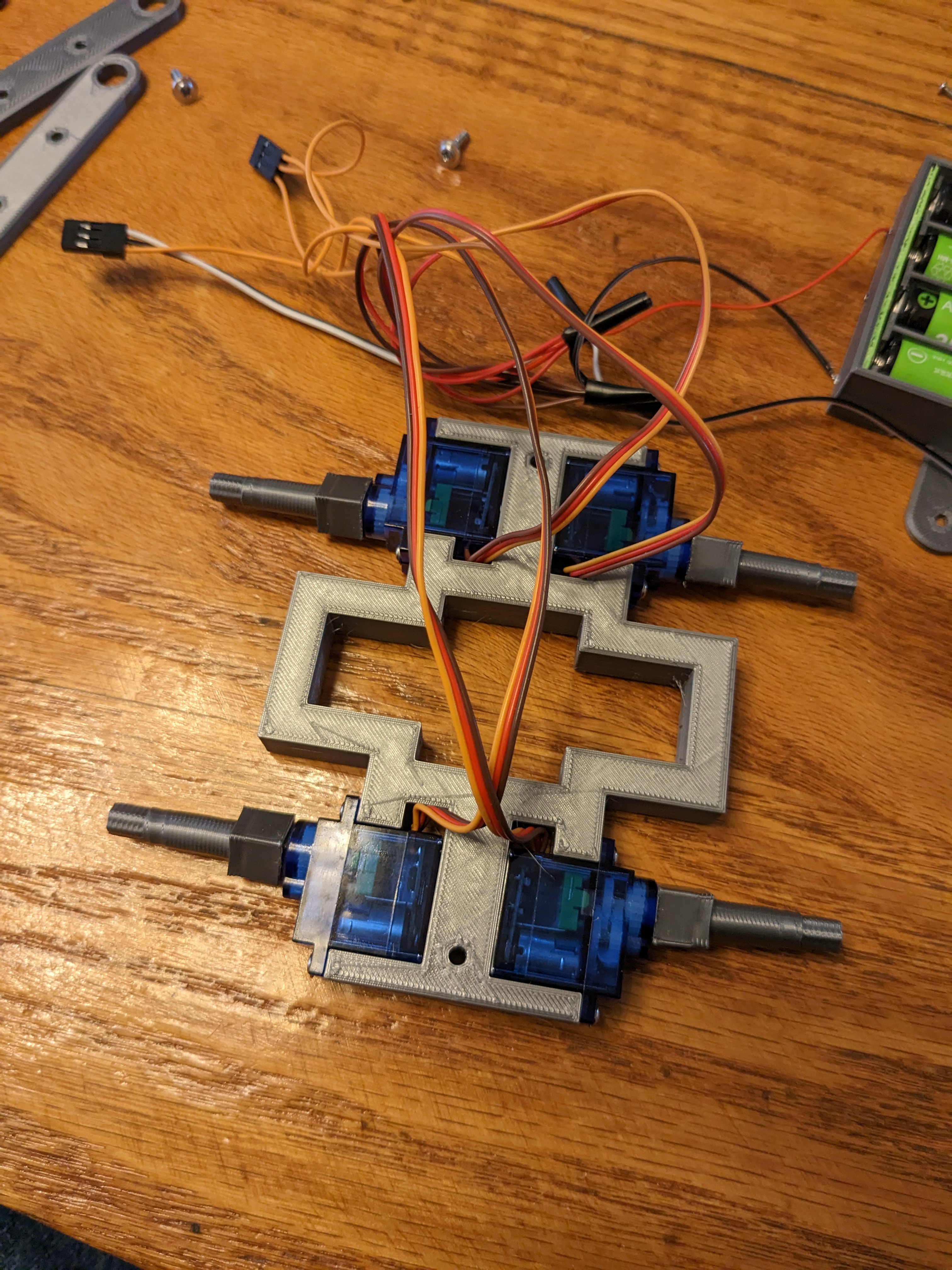
Place the wheel shaft couplings on the shaft squares. They shouldn't be a tight fit, but it's not bad if they are.
![]()
Place the wheel holder bars over the shafts. They must be a loose fit so the shafts can rotate. Fix them in place with 16mm M3 screws. The screws must be a tight fit.
![]()
![]()
-
3Mount the wheels
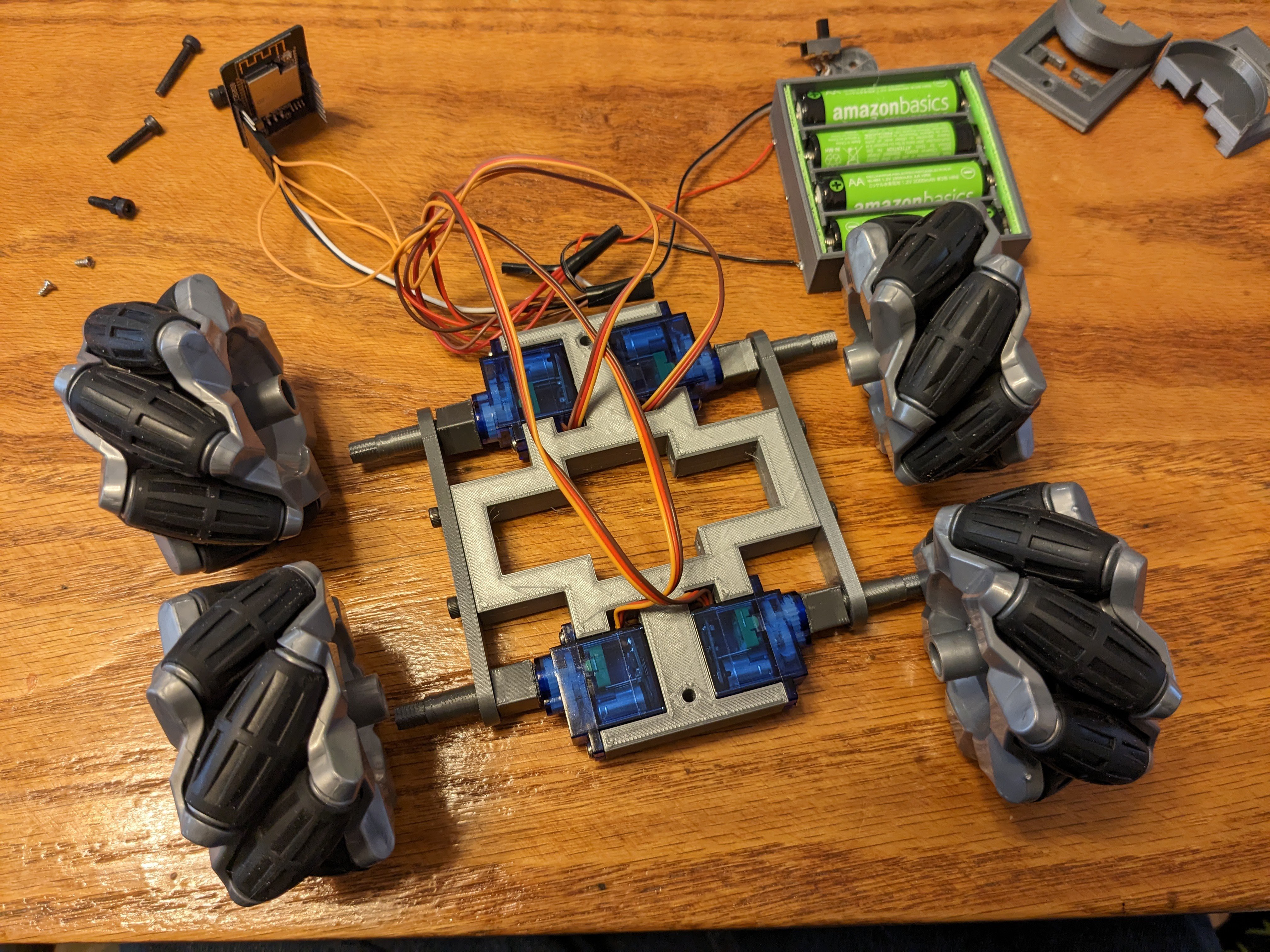
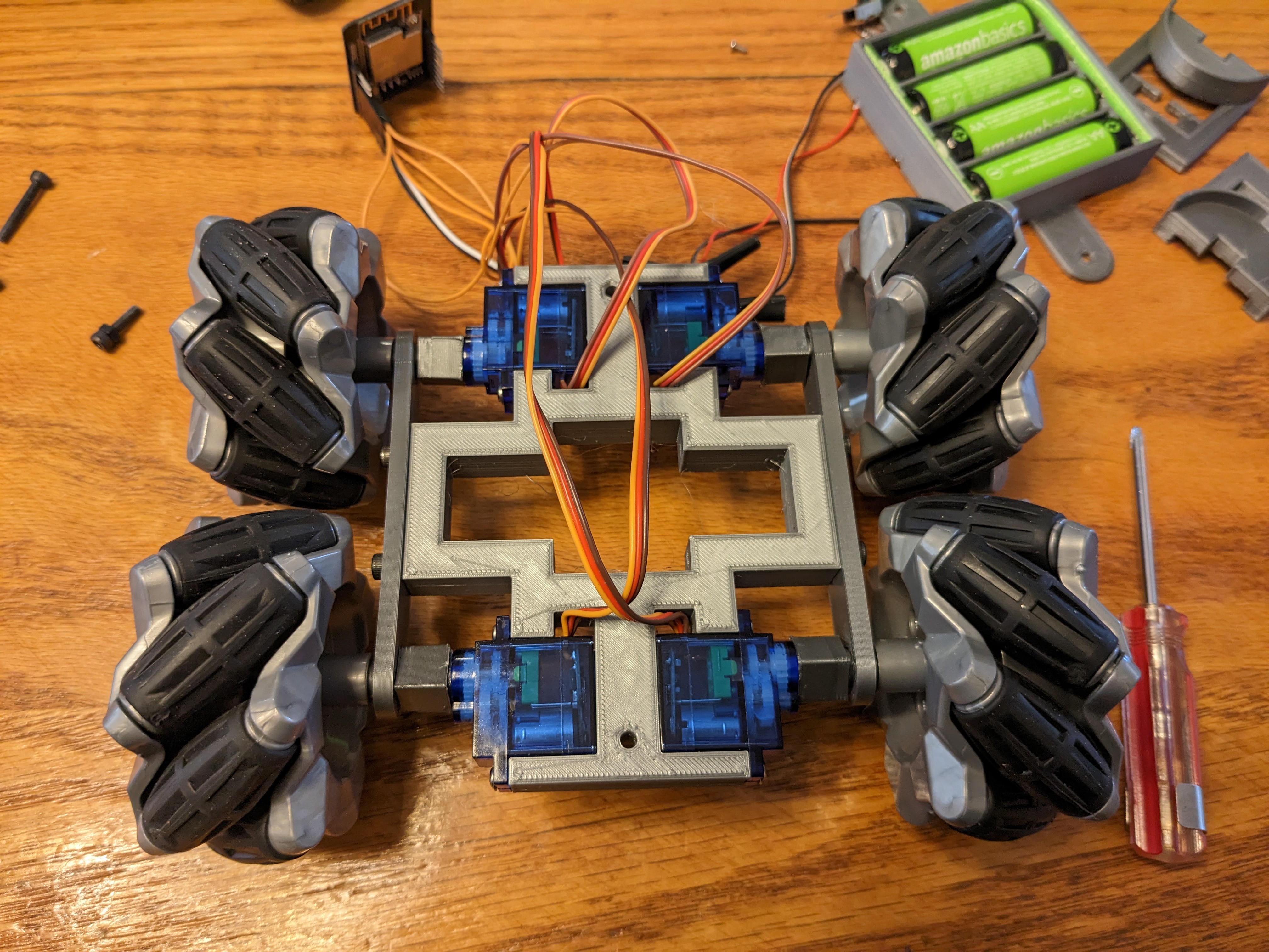
Wheel orientation is critical! The only parts from the toy you need to keep are the wheels and the screws they're mounted with. Note that the toy has many other useful parts, including a motor control IC, 3.2V lithium cell with charging circuitry and many other parts. I'll be putting them in other projects.
If you get the wheels in the wrong order, the kinematic equations in the code won't work. Best case it'll go the wrong directions.
![]()
Use the screws from the toy to hold the wheels on the shafts. The screws must be a tight fit or the wheels will pop off.
![]()
-
4Wiring
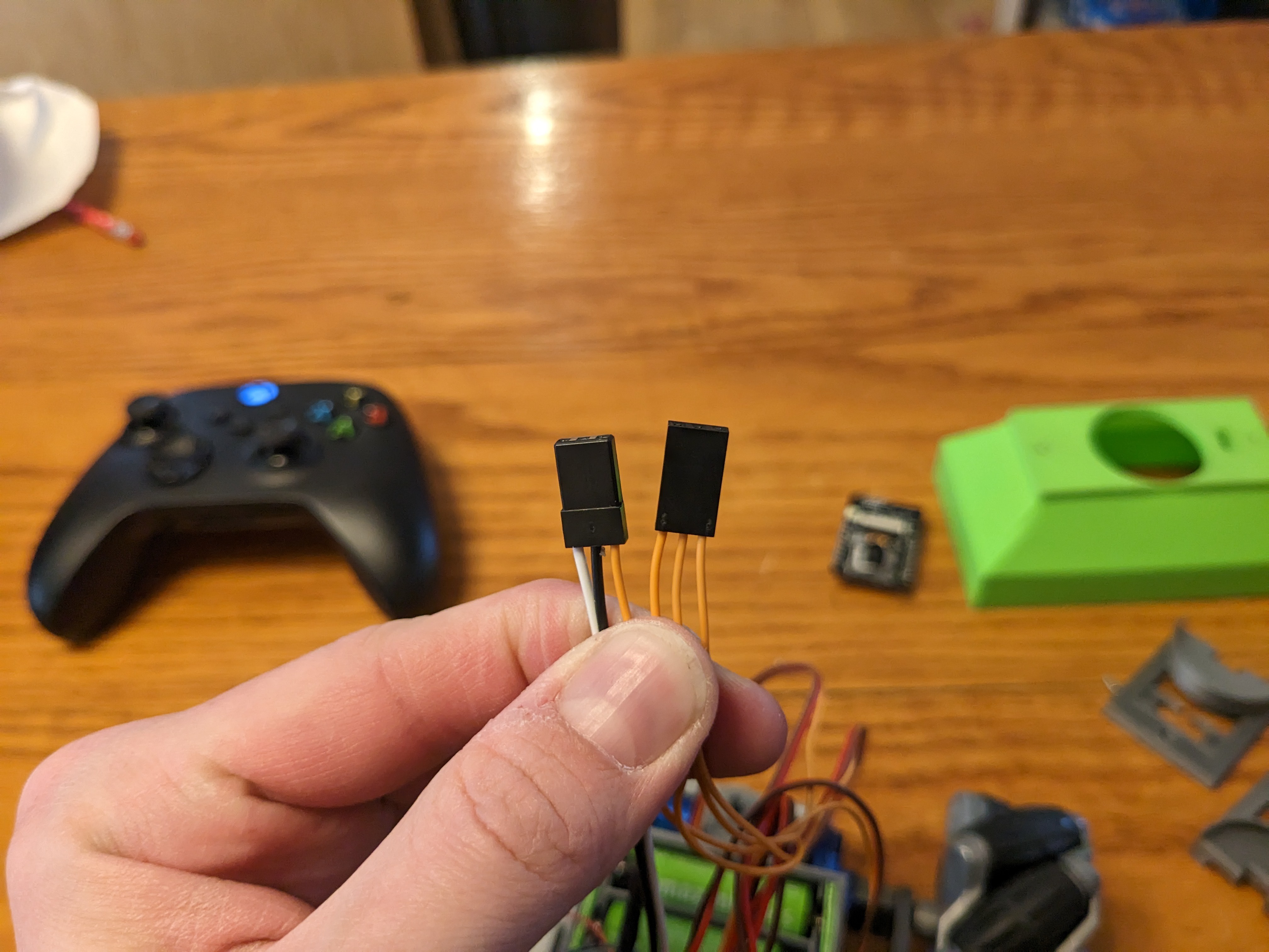
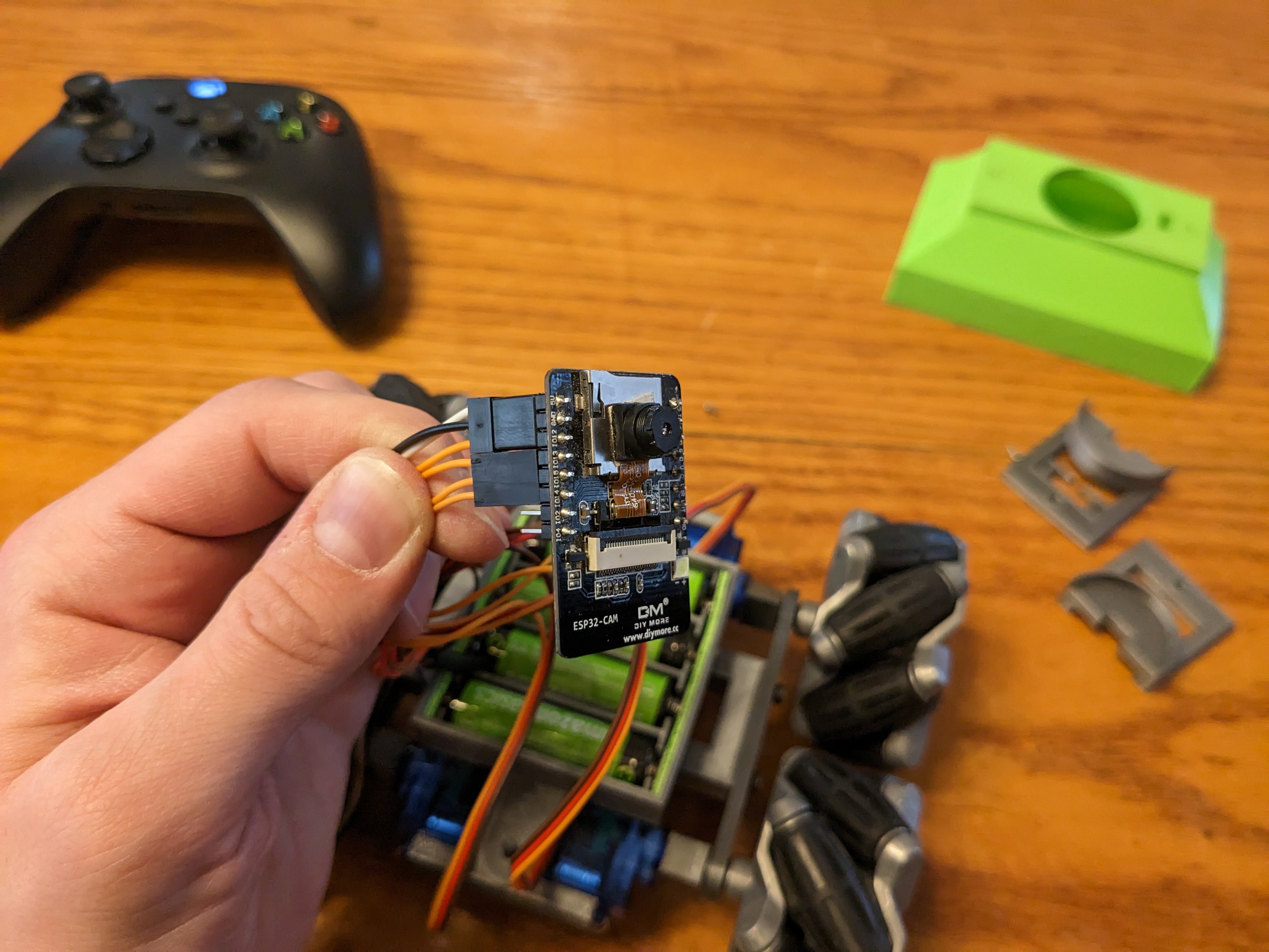
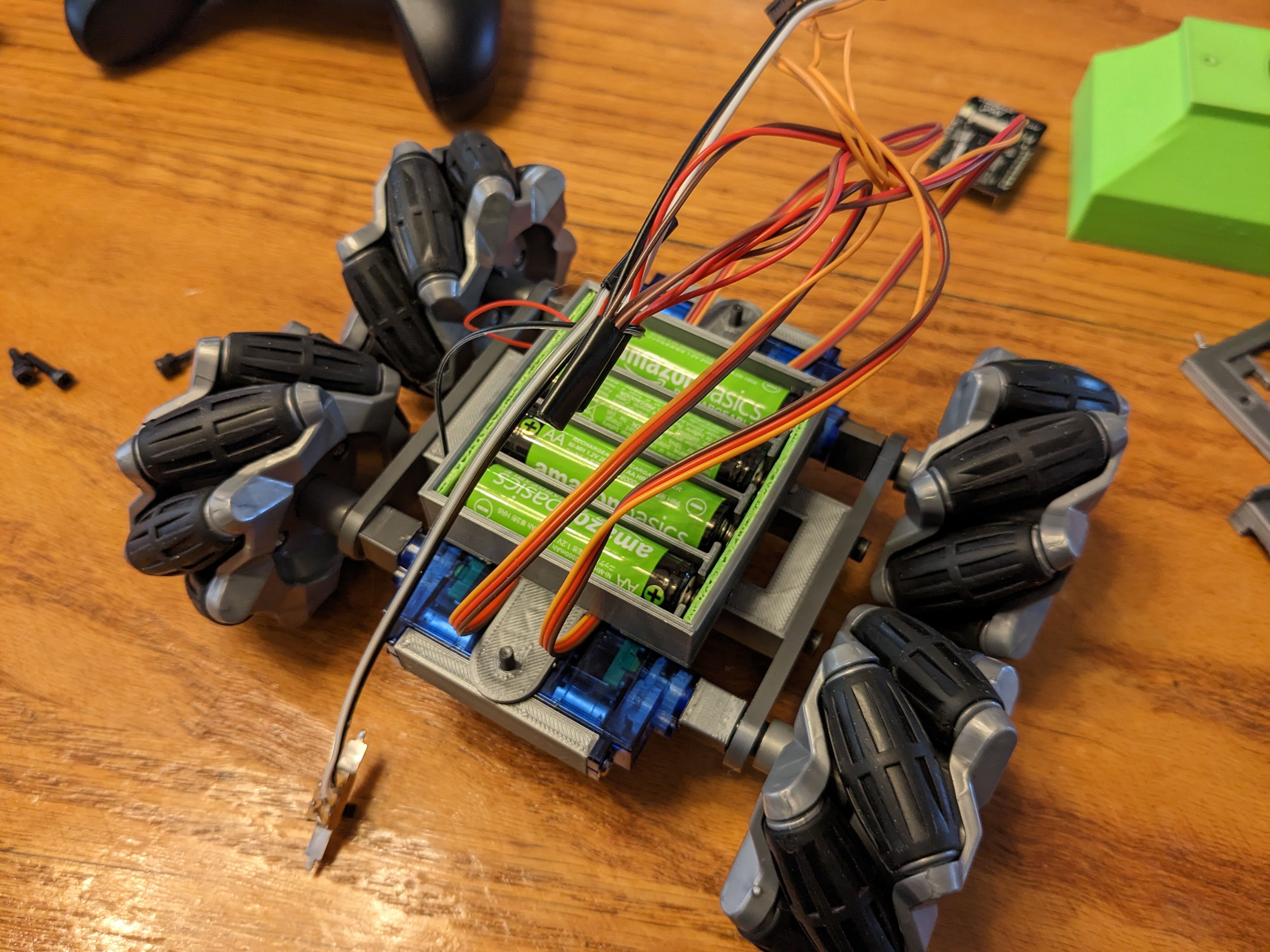
Put the terminals in your battery holder. You'll probably need to make a shim to hold them in place. Next, carefully remove the terminals from the connectors on each servo motor. Keep two of the connectors, we will use them to connect to the ESP32. On the first connector, Insert a wire for positive in the first position (white wire in the picture), and insert a wire for negative in the middle spot. (black wire) Insert the signal wire for the front left motor in the third position. (orange wire) That will correspond to 5V, GND and IO12 on the ESP32. For the second connector, insert the signal wires so that the front right motor goes to IO13, back left on IO15, and back right on IO14. All the motor positive wires (usually red) and the 5V ESP supply (white wire) all connect together and go to the switch and the other switch terminal goes to the positive side of the battery pack. The ESP ground and all the motor GND wires (all black) all go together and connect to the battery pack negative.
![]()
![]()
Don't connect the terminals just yet. Still have to program it. This is just for illustration of how it'll be in the final assembly.
-
5Programming.
I used VSCode with PlatformIO to write and upload the code to the ESP32. Extract all the files to a convenient location and open the folder in the PlatformIO home. It should download and install the required libraries and frameworks automatically, as they're listed in the platformio.ini file. There's plenty of n00b tutorials on installing it and getting the blinkenlights. If you've never used platformio, do some of those first.
Some notes on the HTML code: The ESP32 has a huge ammound of program space for a microcontroller, but nowhere near enough for a modern bloated webapp. So, the code I wrote resides on the ESP32, however, the A-Frame javascript framework is 1.9MB, so it is actually just a link. This means the device accessing the ESP32 must be connected to the internet. So for this reason, the robot must join a wifi network, instead of hosting its own access point.
Also of note, because google continues to suck, the mDNS service is useless on Android. On a computer on the same network as the robot, you can just go to https://panobot.local to access the UI, but that won't work on Android. Additionally, because Google sucks, they removed the ability to view connected device IP addresses on mobile hotspots!
So you really have no simple way to find the robot on the network if you're using an Android mobile hotspot for the robot. If you have a second asndroid device, you can use standard network sniffing tools to find it. I've tried everything I can think of, but the hosted access point is inaccessible to tools on the hosting device. Can't even use a terminal emulator to list the clients without root! Who the hell thought it was a good idea to hide the connected devices from the owner/administrator of the network? /rant.
Anyway, edit the wiif_psk.h file to include your wifi credentials. (yes, I made a typo, no I'm too lazy to fix it now) Then use the platformio UI to build the filesystem image, then upload the image, then build and upload the c++ code. You can open a serial terminal to see its IP address. Android mobile hotspot will assign the same IP until you reboot your phone.
Update 12/25: I just received an Occulus Quest 2! So I'm re-writing some of the UI to be compatible with the Quest's web browser.
-
6Camera assembly and testing
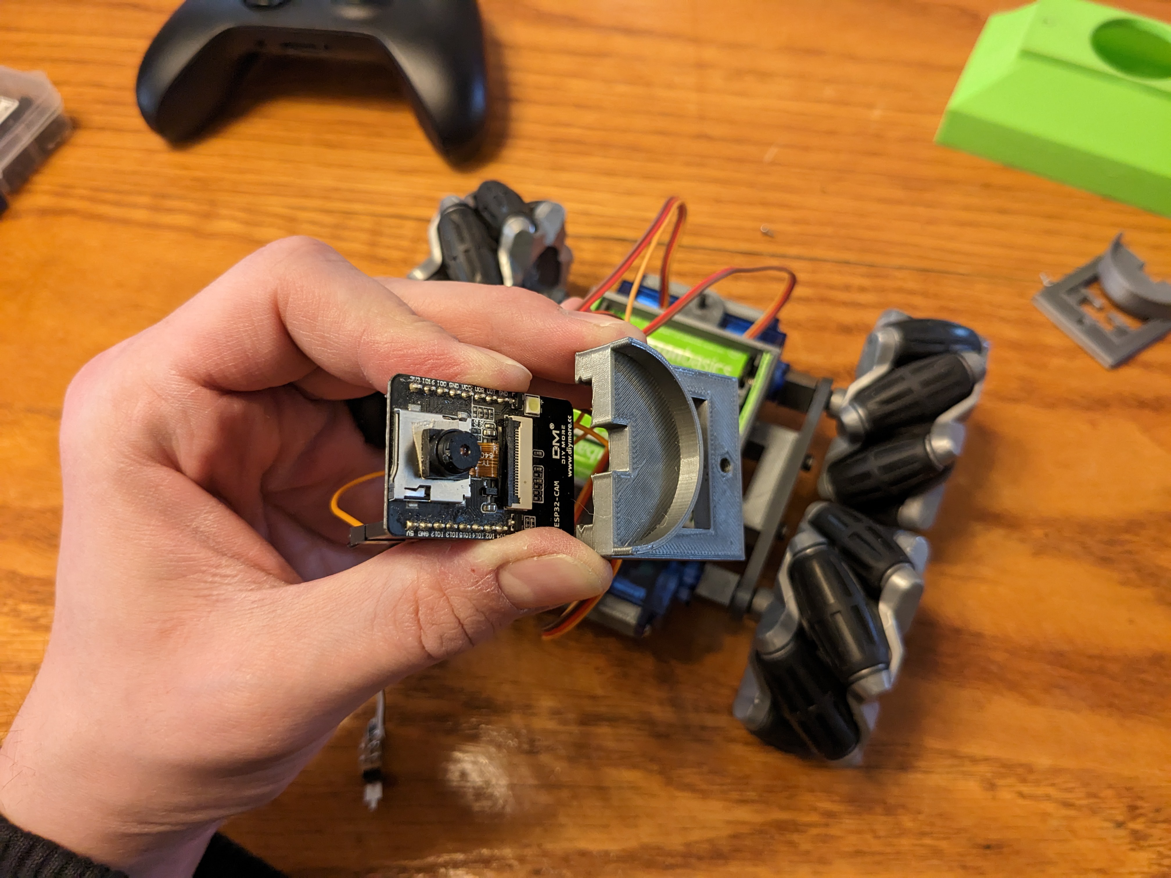
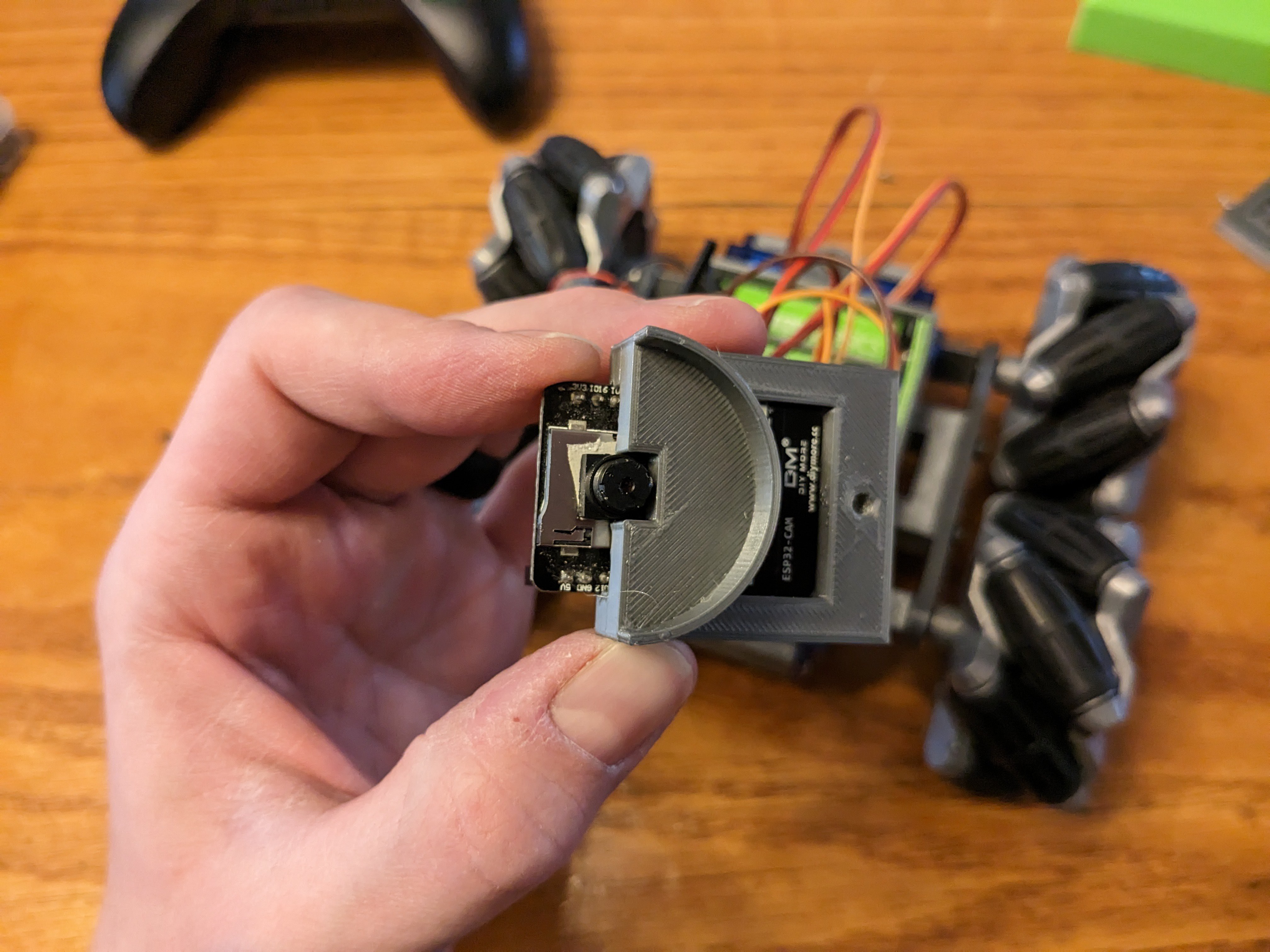
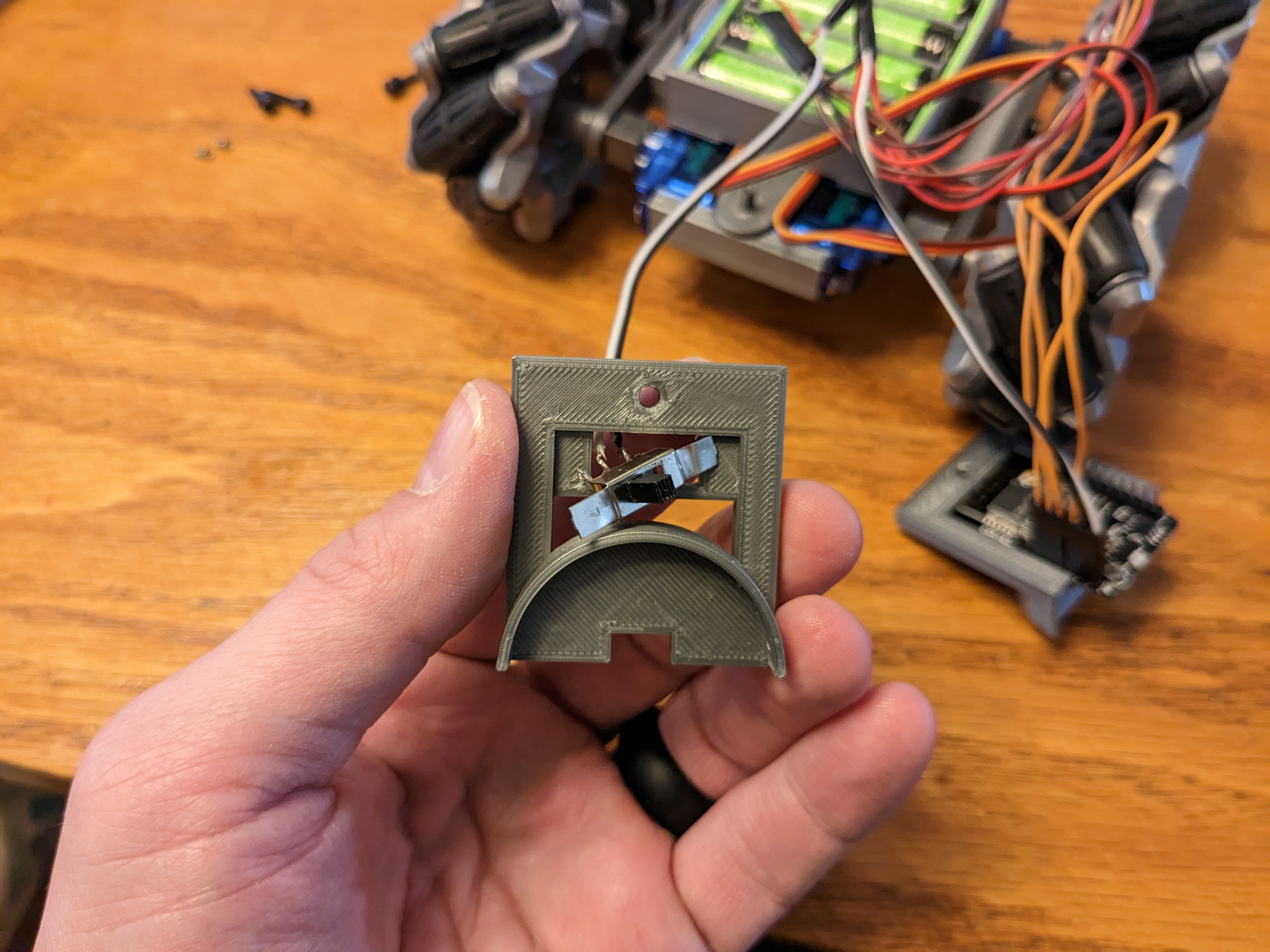
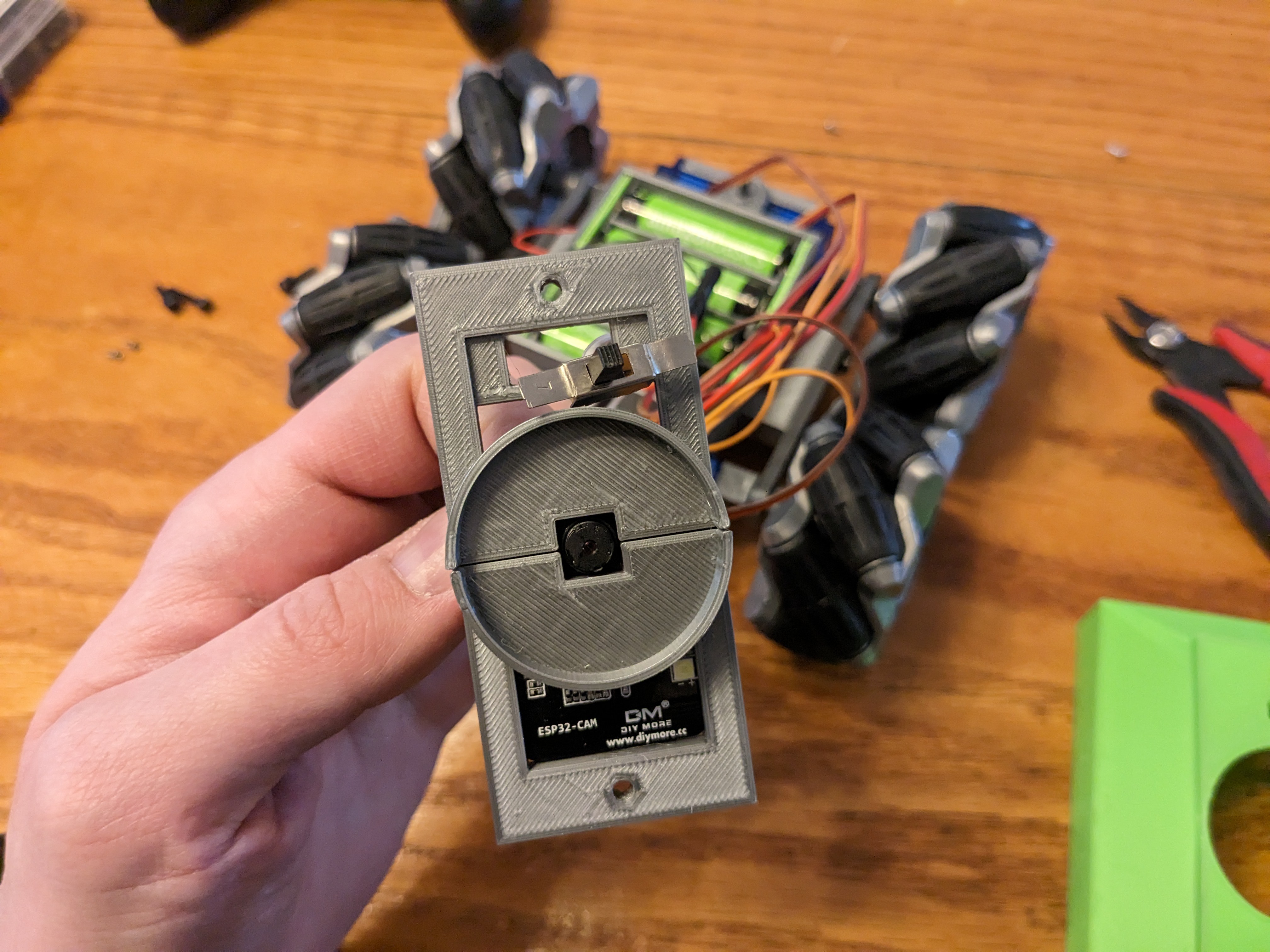
Slide the camera module into Cam holder A, and put your switch in the switch holder on Cam holder B and slide that on to the camera.
![]()
![]()
![]()
![]()
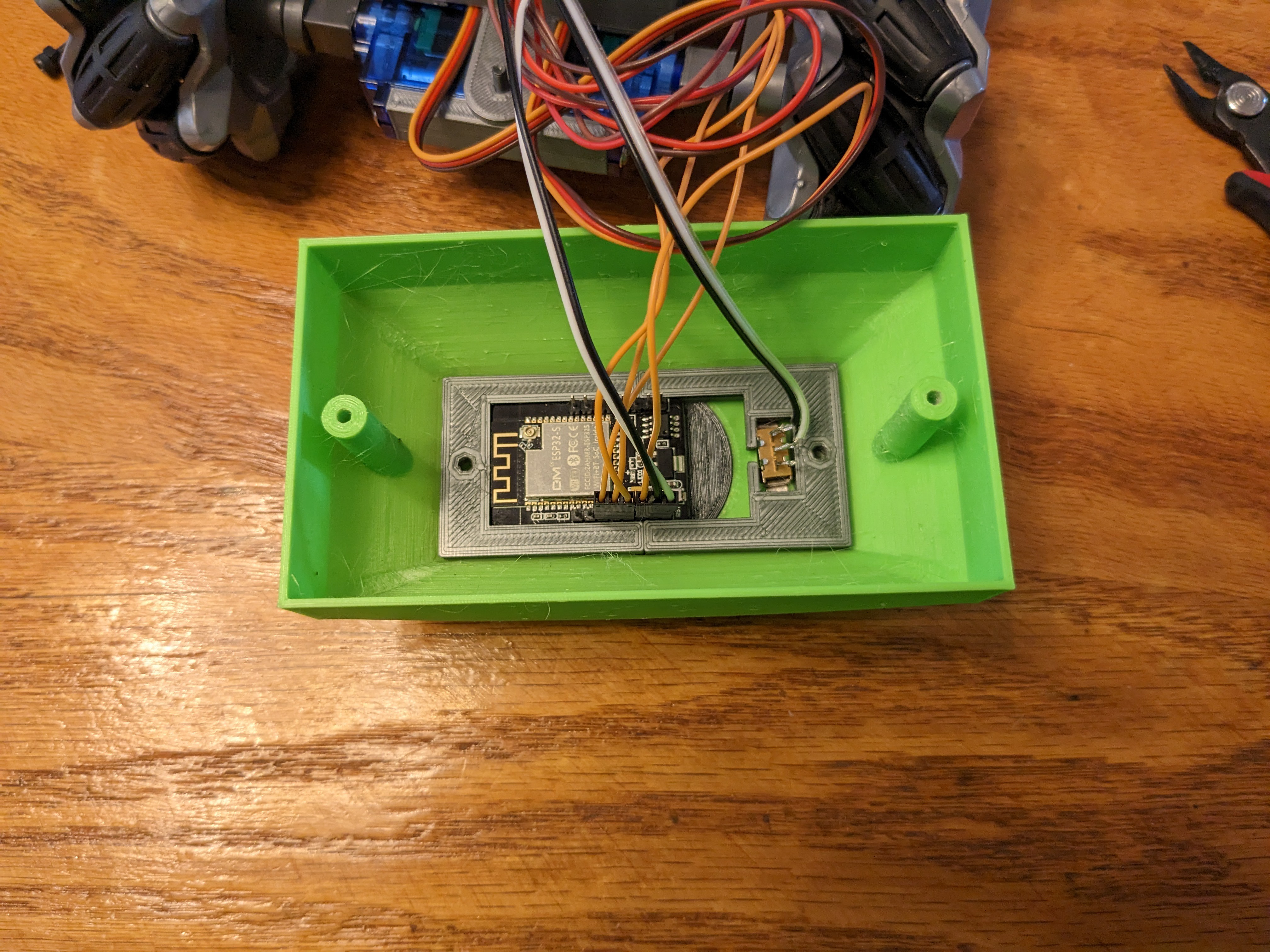
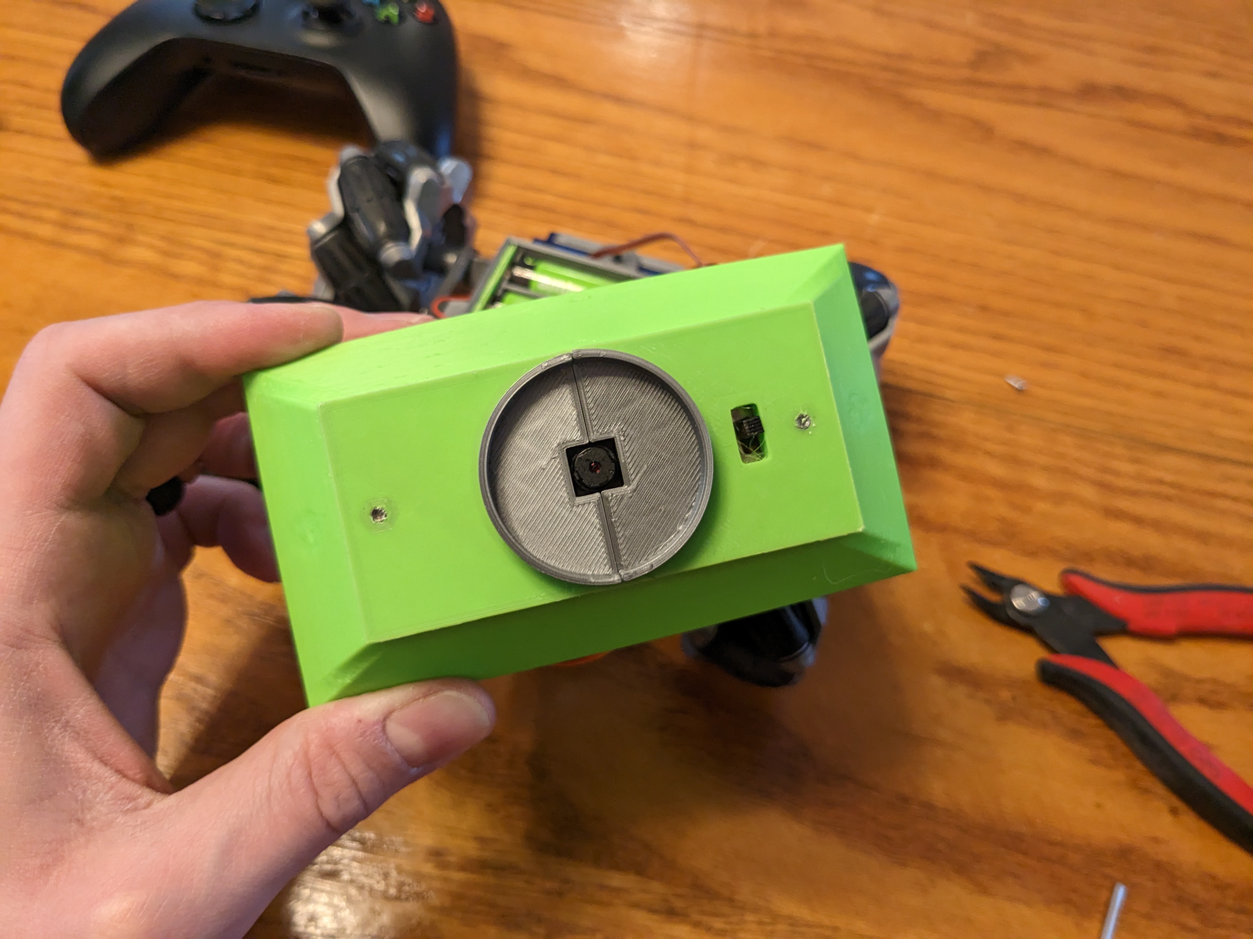
Carefully place the module into the top cover, taking care to align the switch with the hole.
![]()
![]()
Also connect the wires as shown. Motor A should be on IO12, B on IO13, C on IO15 and D on 14.
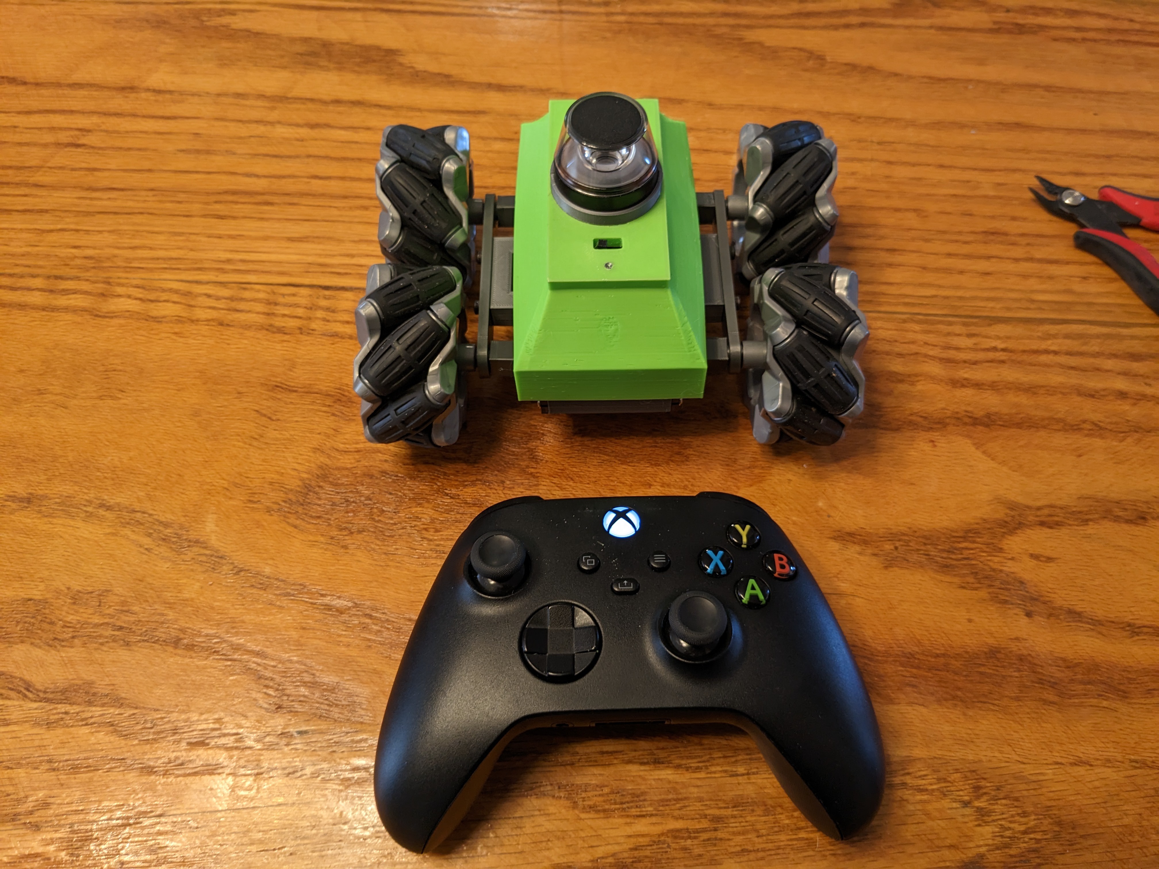
Connect an xbox controller to your computer, power on the robot and navigate to https://panobot.local in your browser of choice. When the video stream starts, move the left joystick upward to check which way is forward. Probably should double check the other directions to be safe. I recommend marking the chasis so you know which way is forward if you open it up again. If all is well, proceed.
-
7Final assembly
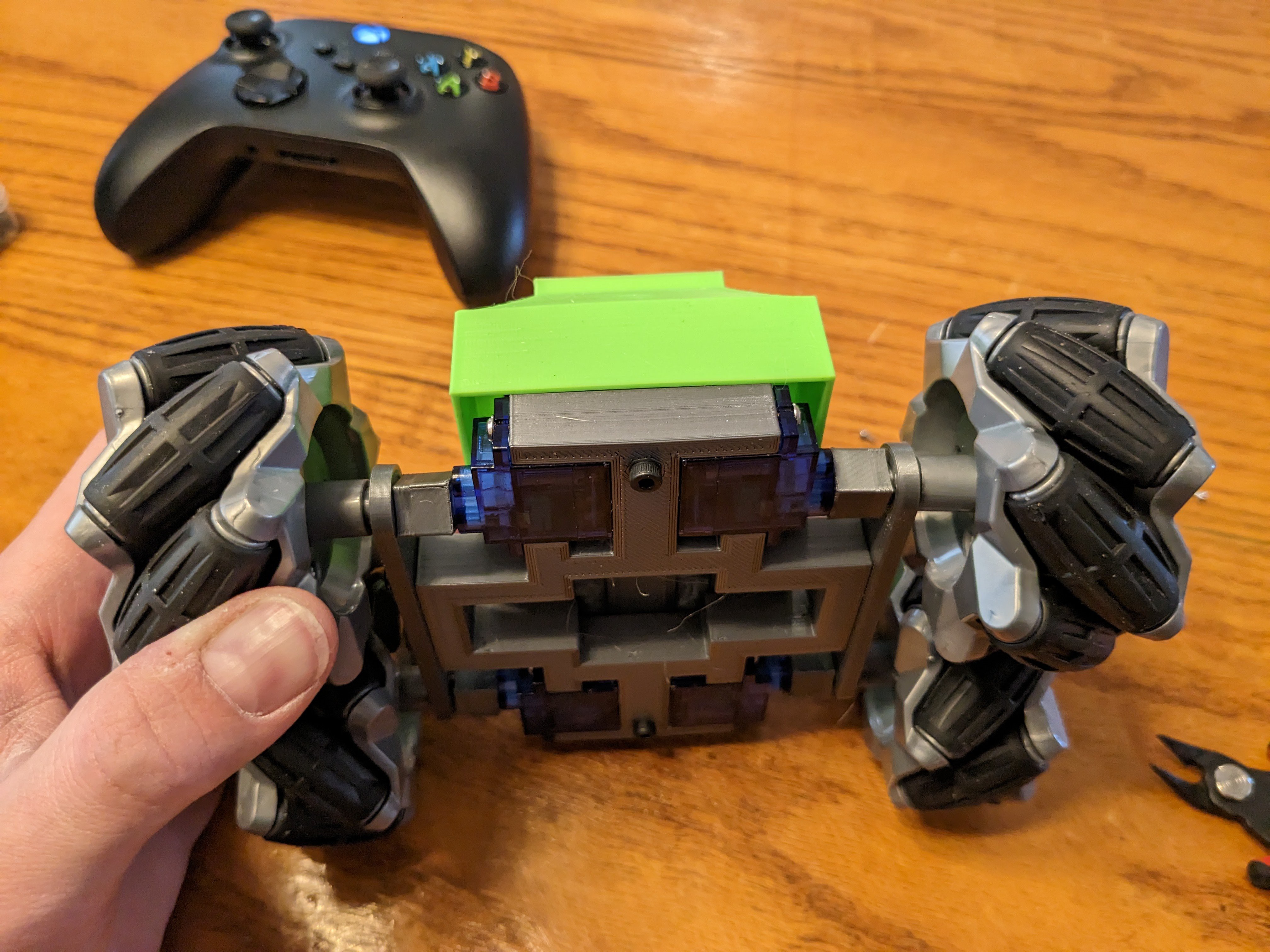
Get two 16mm M3 screws and insert them in the bottom of the chasis and slide the battery holder over them.
![]()
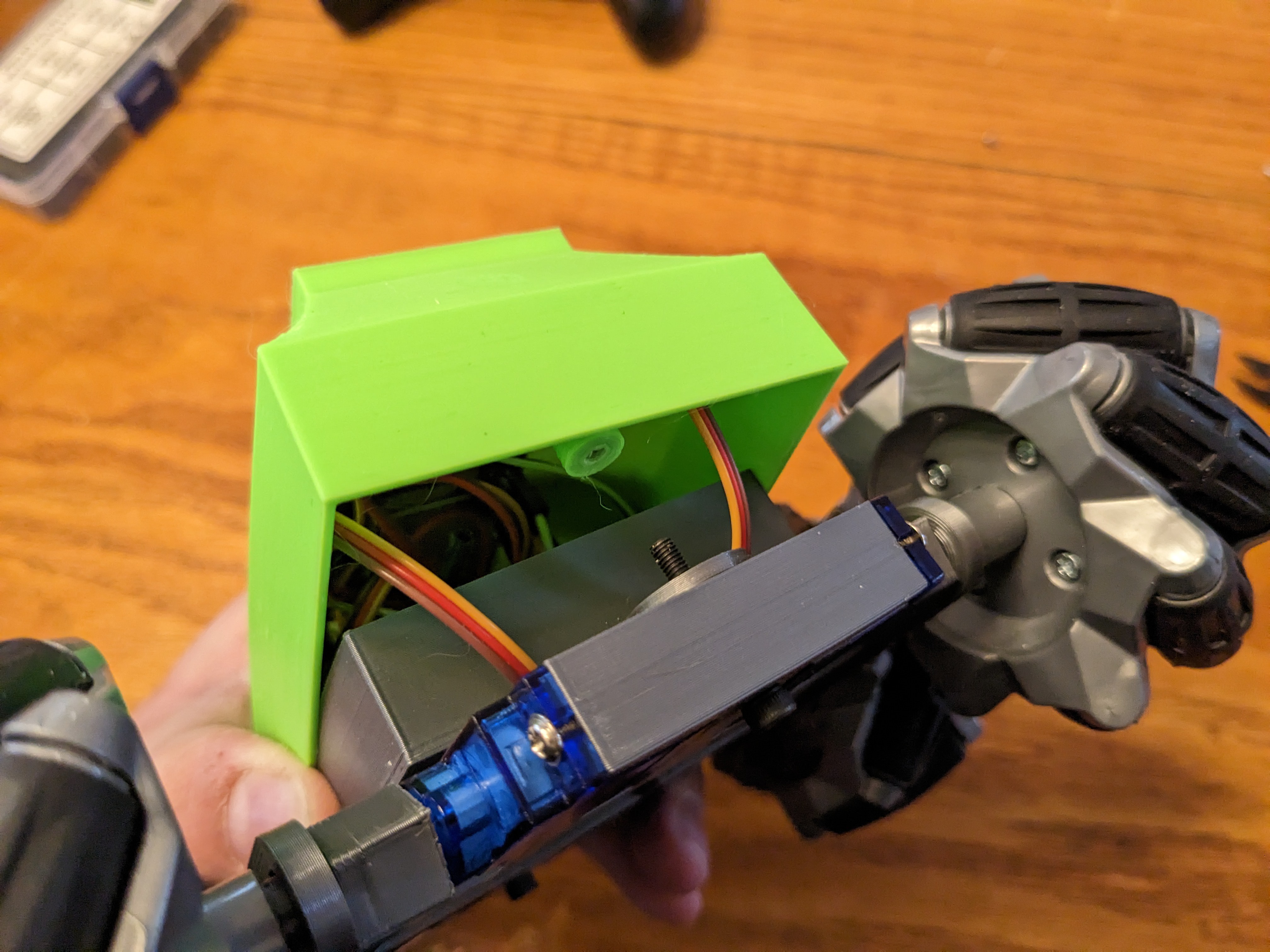
Carefully align the top cover so the screws match with their holes and take care to shove the wires in so they're not pinched. Tighten down the screws until snug.
![]()
![]()
Insert the trimmed Kogeto Dot lens into the holder at the top to finish the assembly. It should be snug enough to stay in position and not to fall out, but just loose enough to adjust. The second version of the Camera board holder has a slightly larger inner diameter and four mounting screw holes, so the lens position can be fine-tuned and locked in place. Use short M3 screws for that if you so chose.
![]()
-
8Operation
There are two modes, VR and Legacy. VR mode is accessed by going to https://panobot.local/vr.html. If you're using a Google Cardboard or Occulus Quest, you'll need to use the IP address https://www.xxx.yyy.zzz/vr.html since Android (upon which Quest is built) ignores mDNS. Touch the VR button to enter immersive mode. In Google Cardboard, you must have an xbox controller connected. Left stick is foreward/lateral and right is turning. In Oculus quest, it uses the touch controller sticks with the same mappings. To calibrate the center, go to the Legacy mode address and use the calibration UI.
Legacy mode is accessed from https://Panobot.local/ on Android, you'll have to use it IP address. This mode uses touch, just like any mobile first person shooter. Hold the phone in landscape for control. Touching and dragging on the right half will control forward and lateral movement, and the left will turn. To open the calibration UI, just turn your phone to portrait and use the sliders. In Quest, set your browser to Mobile display and drag the corners of the window to resize to a portrait or landscape layout. Switching from portrait to landscape will save the settings to your browser cache.
If you switch between VR and Legacy, close the browser tab! It crashes and reboots when the websocket is closed by the browser, so it will just hang if you navigate in the same tab. (That's why I didn't include a link or switch button)
Also, a tip for Android/Quest, if you're on mobile hotspot wifi, connect a laptop to the wifi and go to the UI in your browser of choice, the network tab of the developer tools will show the IP address of the robot. You can then use that on your phone or headset.
Enjoy!
Touch control demonstration:
VR in Cardboard:
VR in Quest:
Discussions
Become a Hackaday.io Member
Create an account to leave a comment. Already have an account? Log In.