 mit41301
-
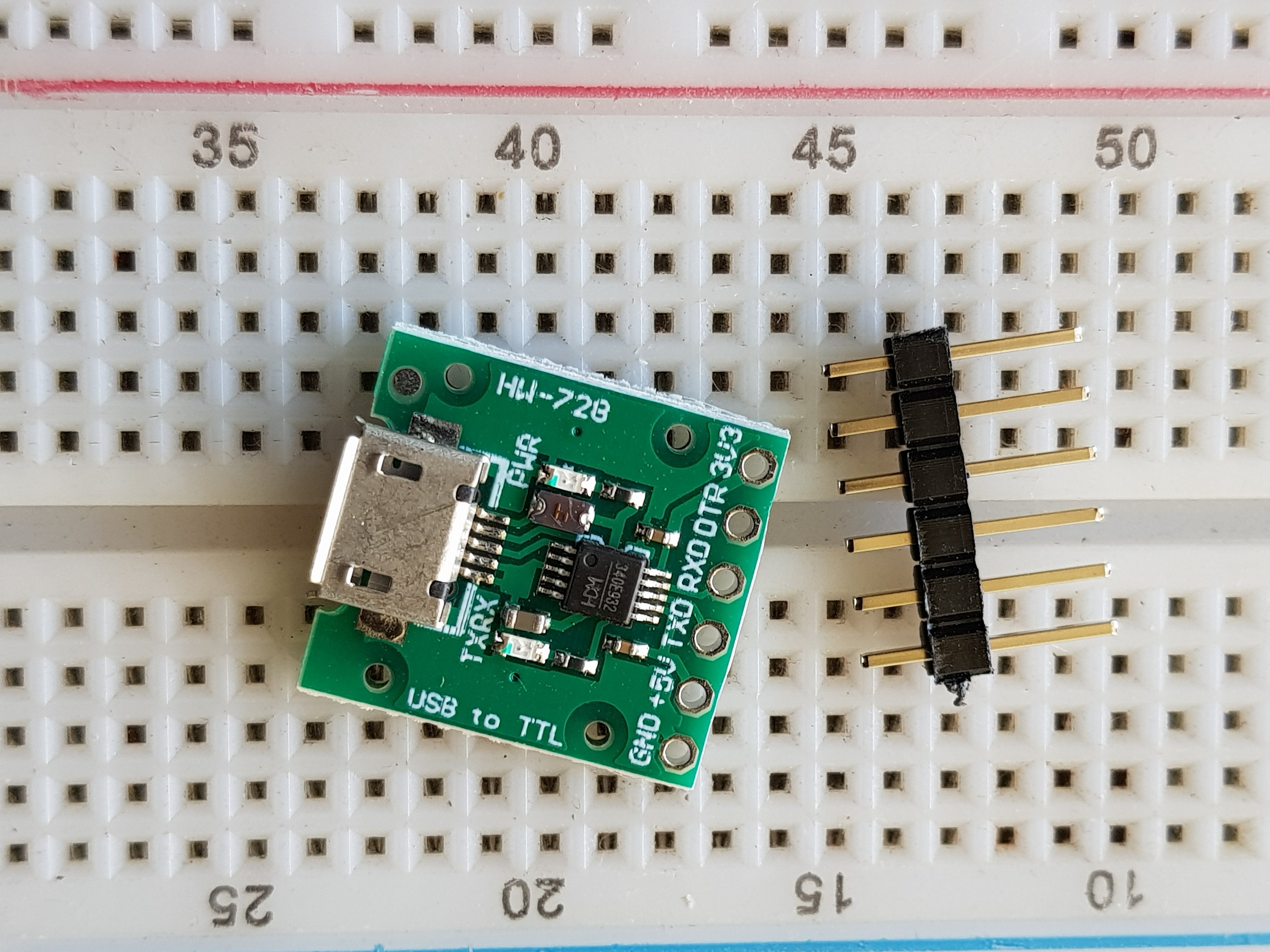
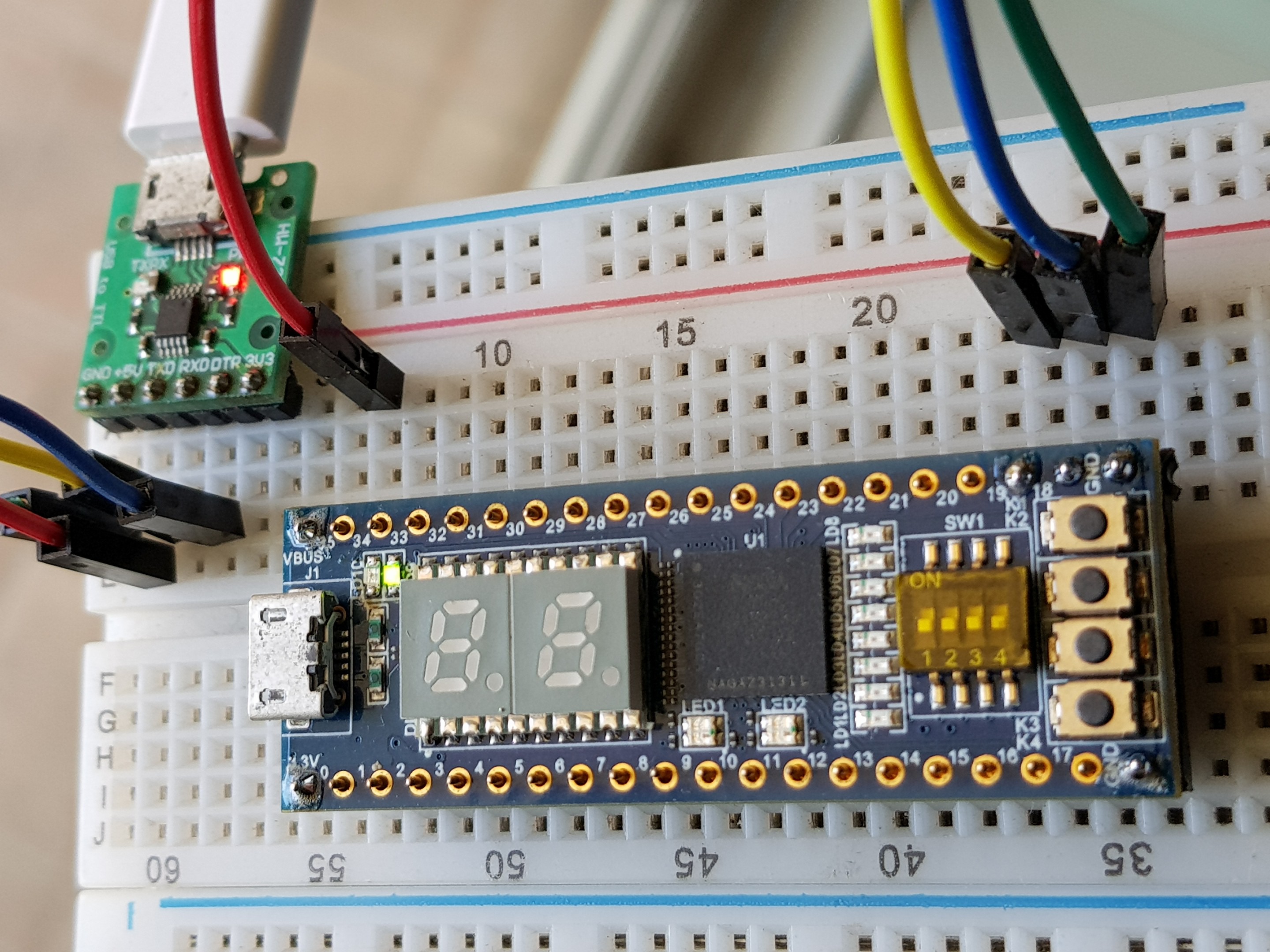
1USB to TTL
![]()
USB to TTL <-> SBC connection
GND <-> GND
+5V<-> VBUS
TDX <-> RXD
RXD <-> TXD
-
2JTAG configuration - SOF file
![]()
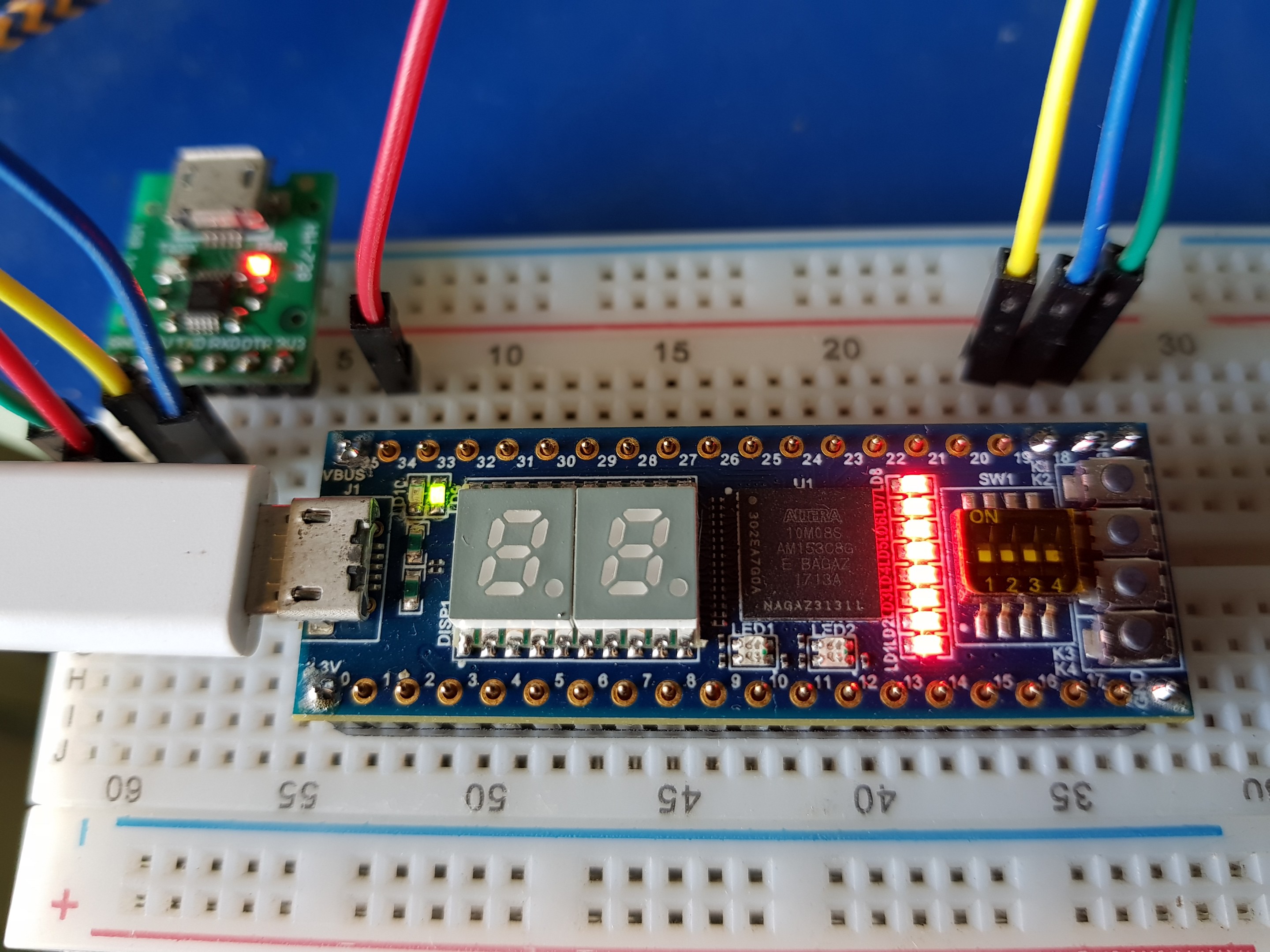
During JTAG configuration Micro-USB cable should be connected to FPGA board connector as shown above. You can see all the eight LEDs are turned ON after successful configuration using SOF
-
3In-System Memory Content Editor - PROG (8k ROM)
We can easily verify the ROM content after successful configuration of FPGA using In-System Memory Content Editor
-
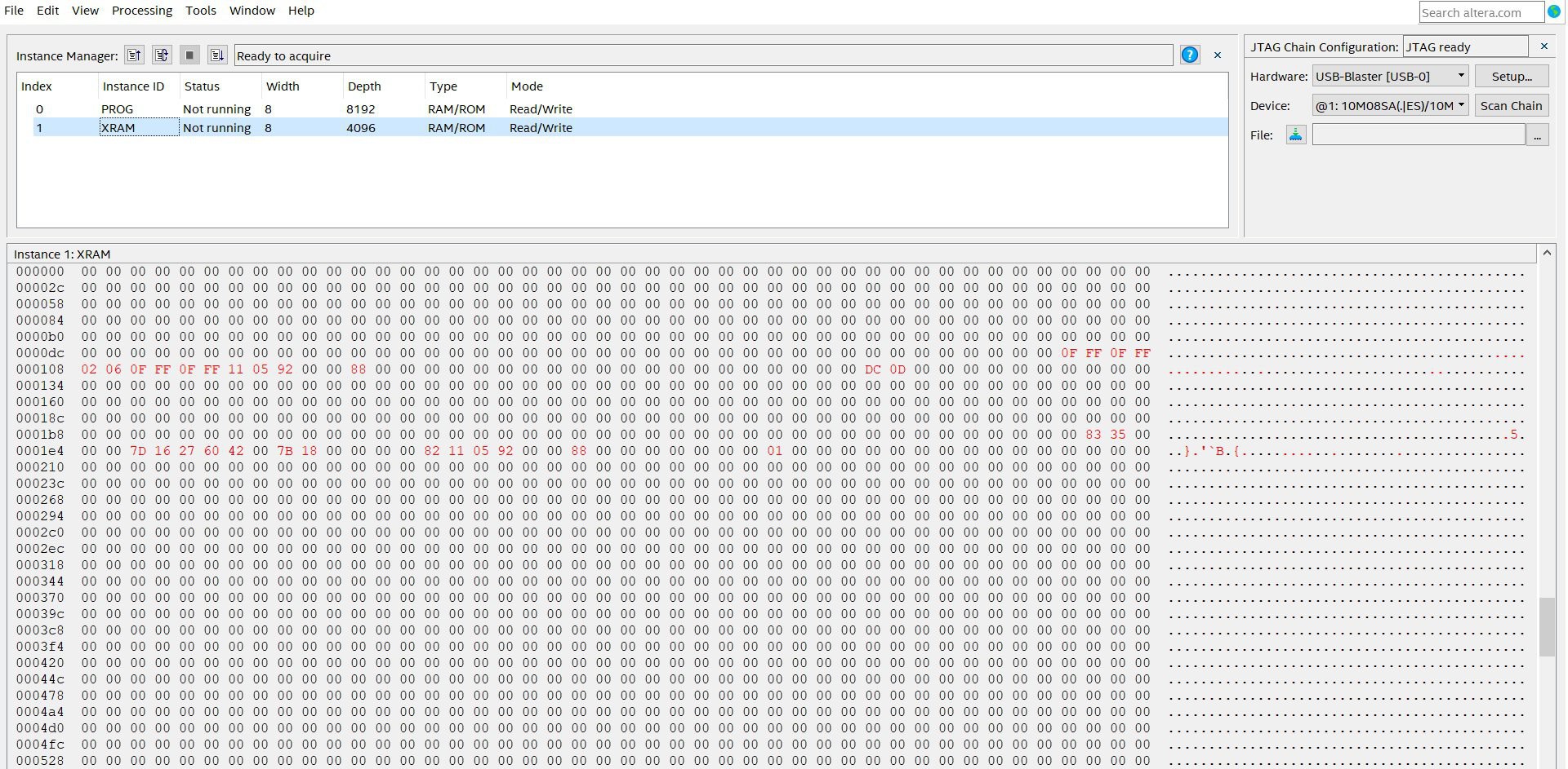
4In-System Memory Content Editor - XRAM (4k RAM)
![]()
We can easily verify the XRAM content after successful configuration of FPGA using In-System Memory Content Editor
-
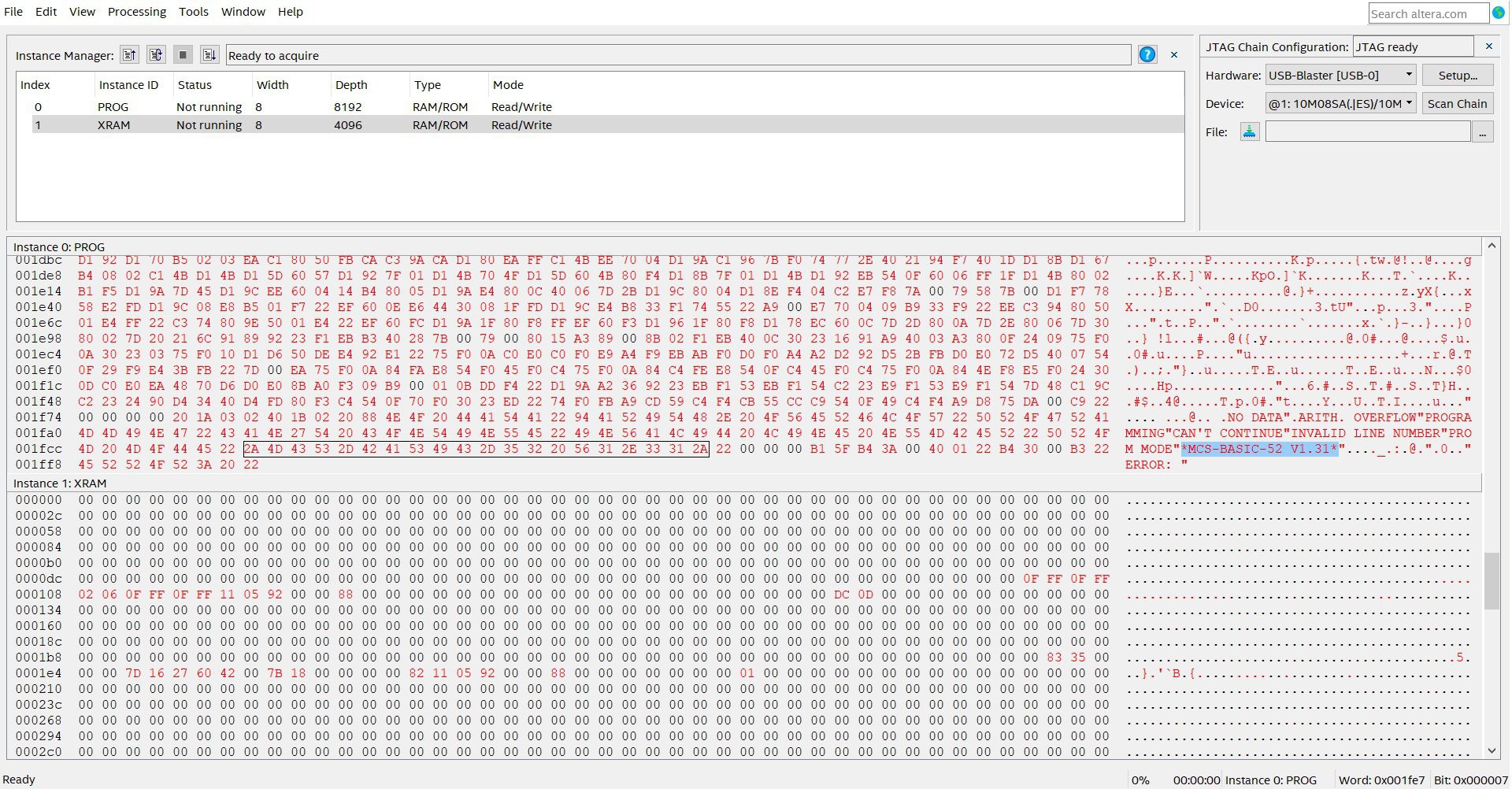
5Confirm the ROM version and program the POF file into FPGA
![]()
We can see the "MCS-BASIC-52 V1.31" at the end of 8k ROM memory as shown above
-
6TeraTerm
![]()
Install TeraTerm or Putty. Run the application. Select the COM port and default baud will be 9600.
-
7Hit the SPACEBAR!
![]()
After hitting the spacebar the following message should appear on the screen.
*MCS-BASIC-52 V1.31*
READY message
Now we can write any application using BASIC-52
-
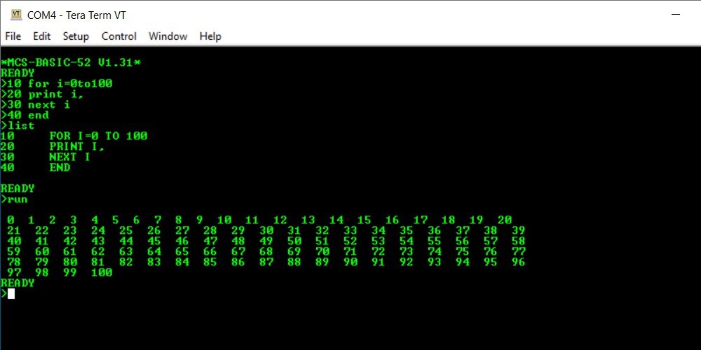
8PRINTING ON THE SCREEN
-
9BIGGER AND LONGER
-
108 LEDs control using PORT 1
8052AH-BASIC single-board computer
Easy way to upgrade your 80C32/8052AH-BASIC single-board computer into a VHDL based 8052AH-BASIC using a FPGA without a device programmer!
Discussions
Become a Hackaday.io Member
Create an account to leave a comment. Already have an account? Log In.