 Kody Alan Rogers
-
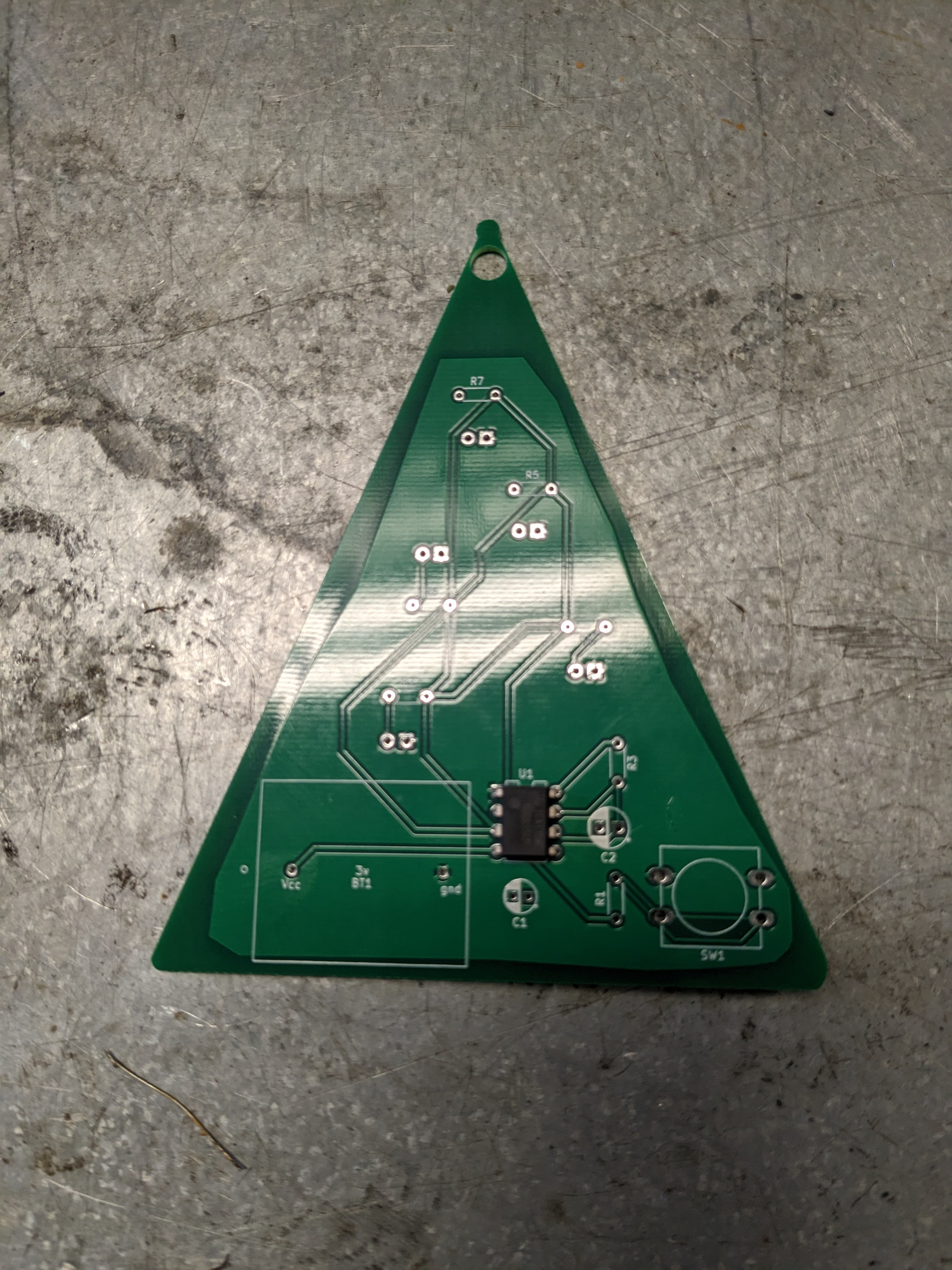
1Place and solder the timer
![]()
Shown above is the Christmas tree version but it is the same for the other versions. It mounts on the side without the picture on the silkscreen. Ensure pin one is oriented correctly.
-
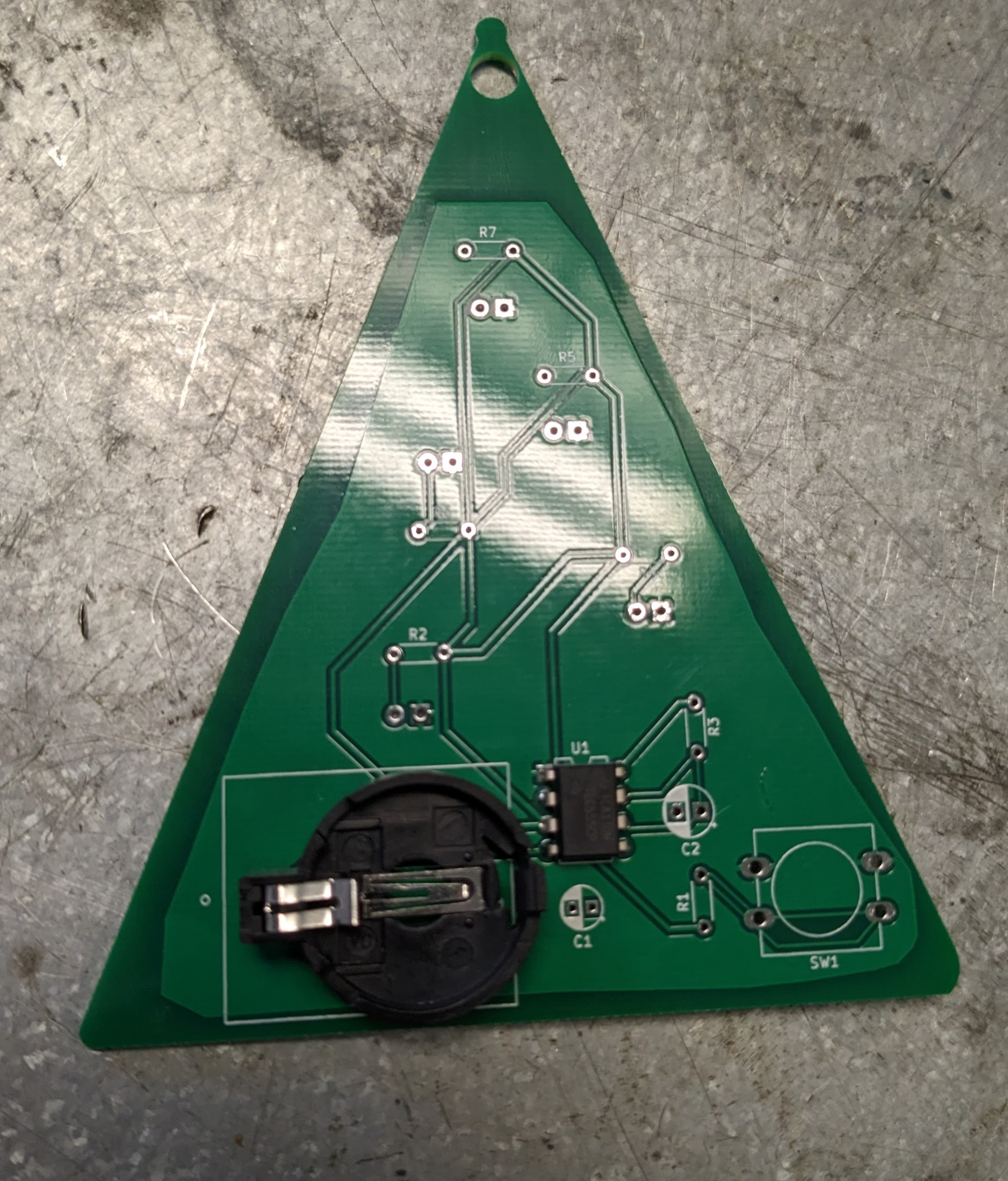
2Place and solder the Battery Holder
Again the Christmas tree version is shown. The Easter Egg version is different in that it has two battery holders. Note that positive and negative ends are pointed out and the positive end of the battery holder is the one that has the square back.
![]()
-
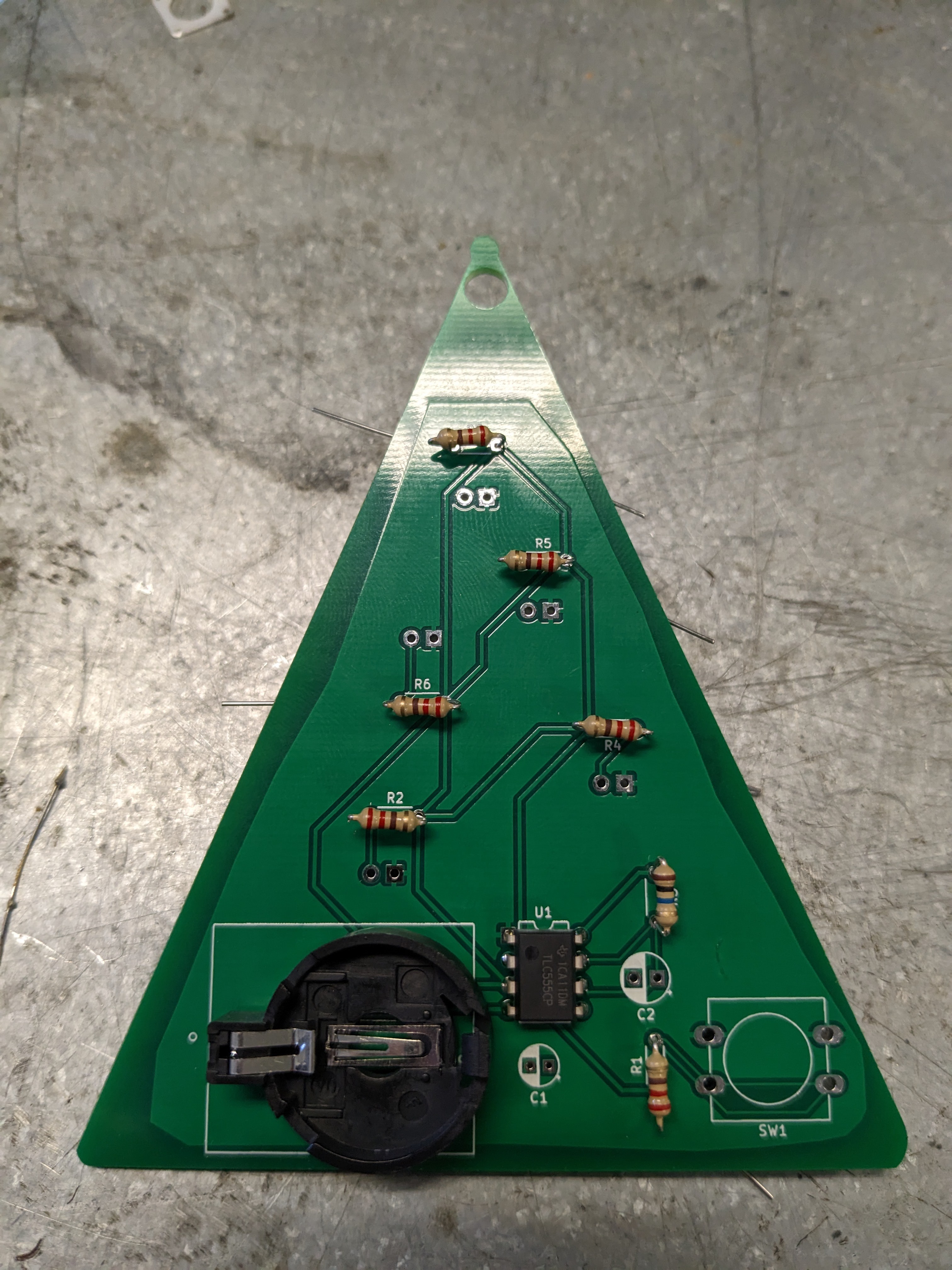
3Place and Solder the Resistors
Shown is the Christmas tree version, but the other versions are very similar. All resistors are the same except for the timing resistor with is 10M Ohm.
![]()
-
4Place and Solder the Capacitors
![]()
Again shown is the Christmas tree version, but the other versions are similar. The are two capacitors one polarized (the timing capacitor) and the other unpolarized which is connected to the control pin. See the schematic for more specific information.
-
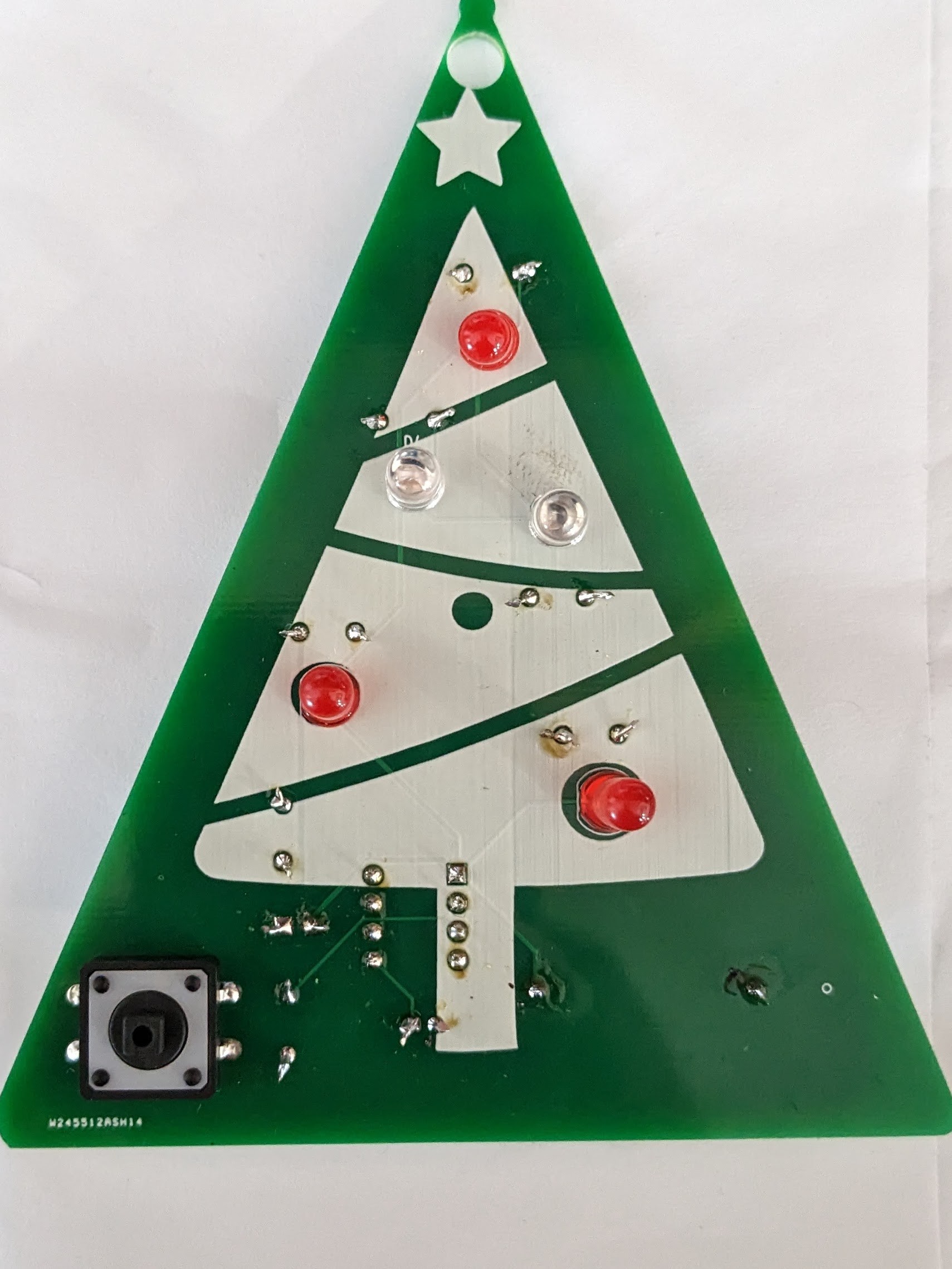
5Place and solder the push button
Again shown is the Christmas tree version, but the other versions are similar. It can only be placed the correct way as far as I know so, place it where it is in the photo.
![]()
-
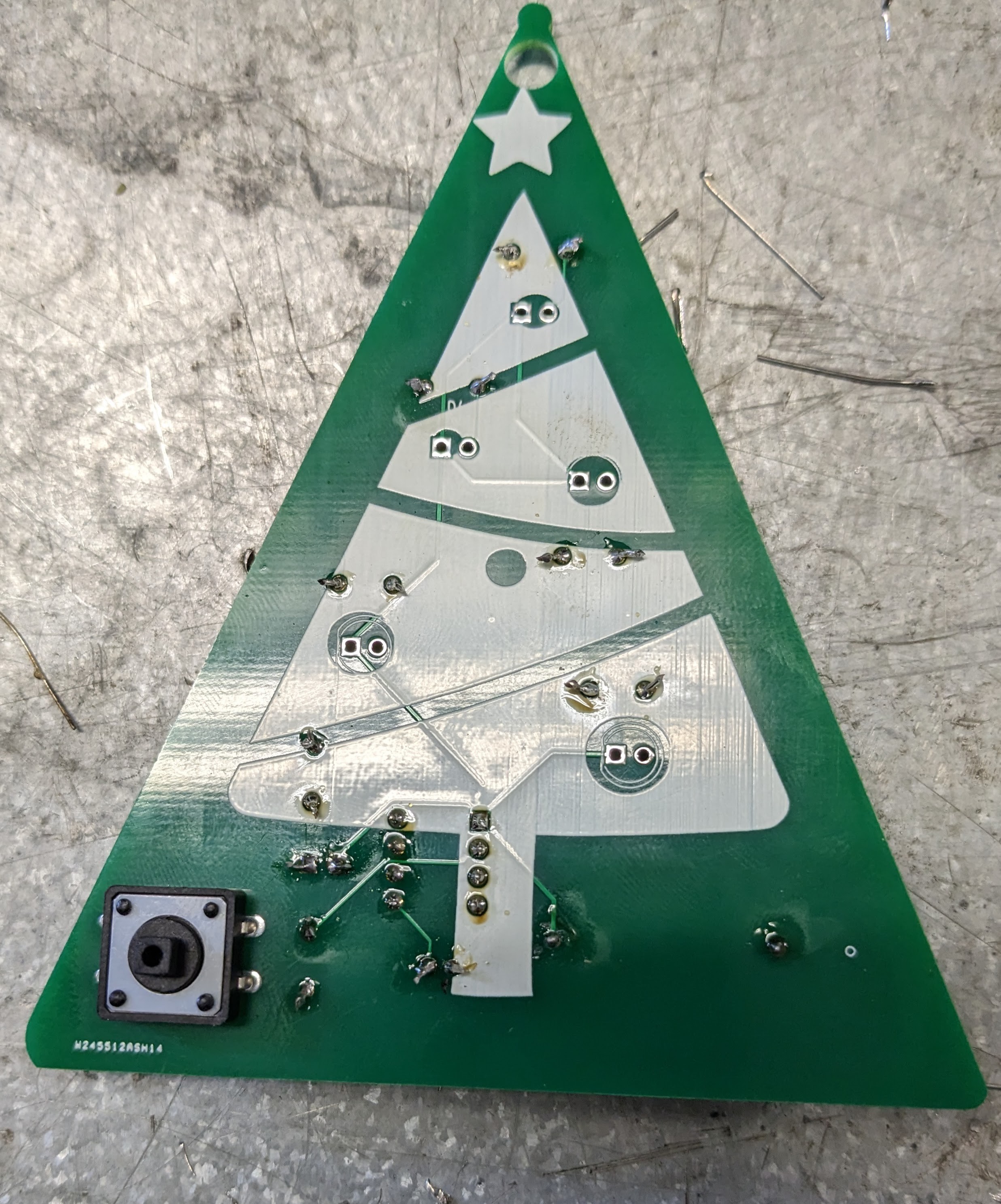
6Place and solder the LEDs
The LEDs listed in the necessary parts are for the easter egg version and shown is the Christmas tree version which uses different ones. Either way, using lights with a voltage drop of 2V will work well.
![]()
-
7Try It Out
The YouTube video that I shared in an earlier post shows how it works. Keep your eye out for posts going deeper into the math of how it all works, but for now you can check out the schematic that was previously loaded for that math.
555 Timer Decorations (Monstable)
This project shows how to make simple light-up decorations with a 555 timer.

Discussions
Become a Hackaday.io Member
Create an account to leave a comment. Already have an account? Log In.