While I was measuring the consumption of other projects I realised that I really need to take care of the wiring. Especially the GND connection. Eventually I destroyed one chip through misconnection.
That led me to the point that the device needs to be isolated. Only this way it is safe to use two of them to perform efficiancy measurements.
There are two ways of isolating the PPPM:
Isolating the input USB connection.
Isolating the onboard power and I2C.
I decided to to the latter because I have no access to the USB-C connection on my PCB.
After a brief search online I found the I2C isolating chip: ISO1641B from TI. It is very easy to use and needs only two external bypass capacitors. The Clock is transmitted unidirectional and the data is bidirectional.
For the power isolation is was a bit harder to find a good space saving solution. Usually there are chips that drive a discrete transformer and on the secondary side you need a LDO to regulate the correct voltage. All that leads to a high BOM count and needed space.
But I was lucky and discovered that TI is coming up with a highly integrated, space saving and cheap chip that does all of this! It is the UCC33420.
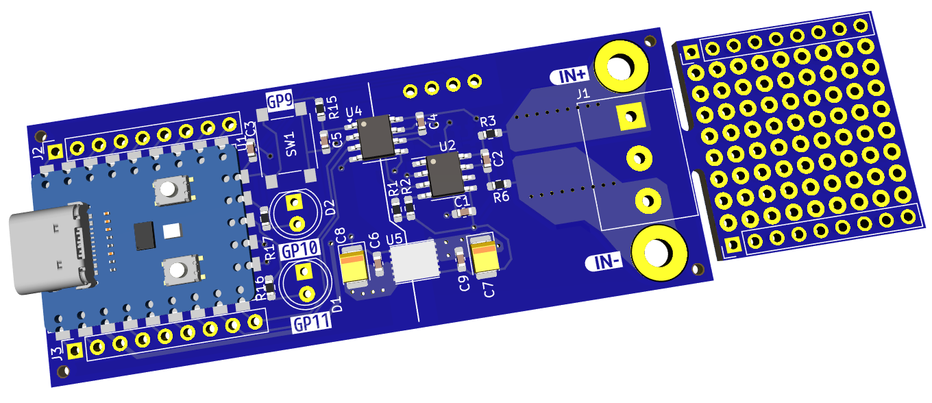
To make space for the two additional chips I moved some components around. The shunt resistor and a couple of resistors moved to the back side of the PCB. Now they can be changed without removing the OLED. I should have done this before!
The layout is done and the PCBs are ordered! Now let's wait for it and that the transformer chip becomes public available.
I disabled the THT components to see below the OLED display.
During testing the Power Meter I discovered some minor things I wish I had done different.
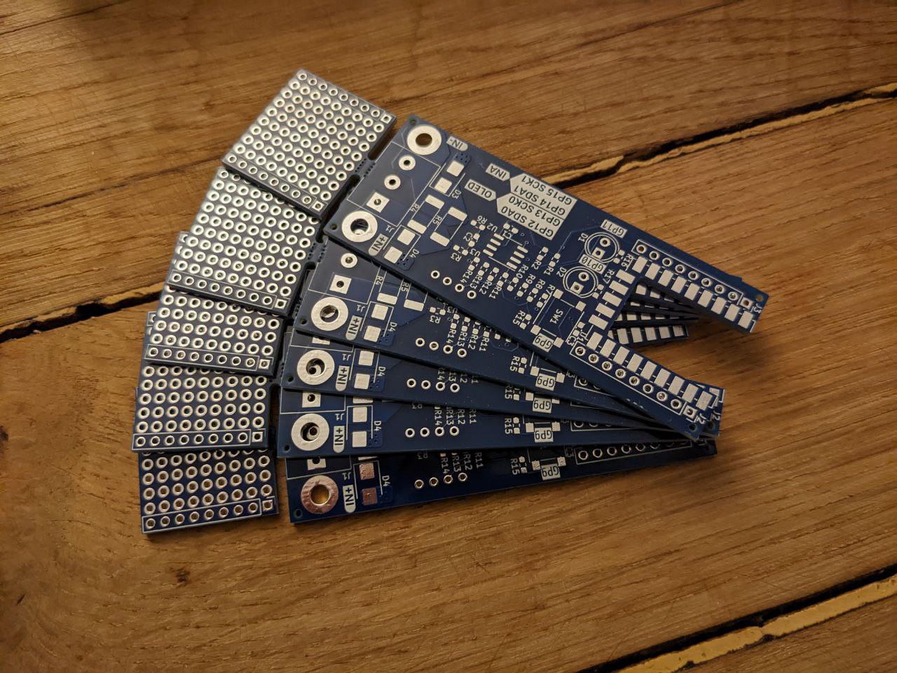
First, and most important I wanted to get rid of the pin headers to solder the MCU module. This only adds costs and is unconvenient. I also added some TVS diodes for the measurement inputs and a mouse bite divideable protoboard for the controller headers.
Before, I got a message from PCBway that they would like to sponsor the next revision of PCBs.
That's a really nice circumstance and I used the offer for new PCBs. It was the first time I ordered there. The PCBs are really nice - like I expected. The HASL finish looks very even and the silkscreen is very clear and sharp. One thing I did not expect was the outer milling of the boards. Often the outline is not that important than the dimensions on top of the FR4. But nothing caught my eye that was not finished perfectly and all the dimensions are bang on! All in all a very good job! Thank you very much!
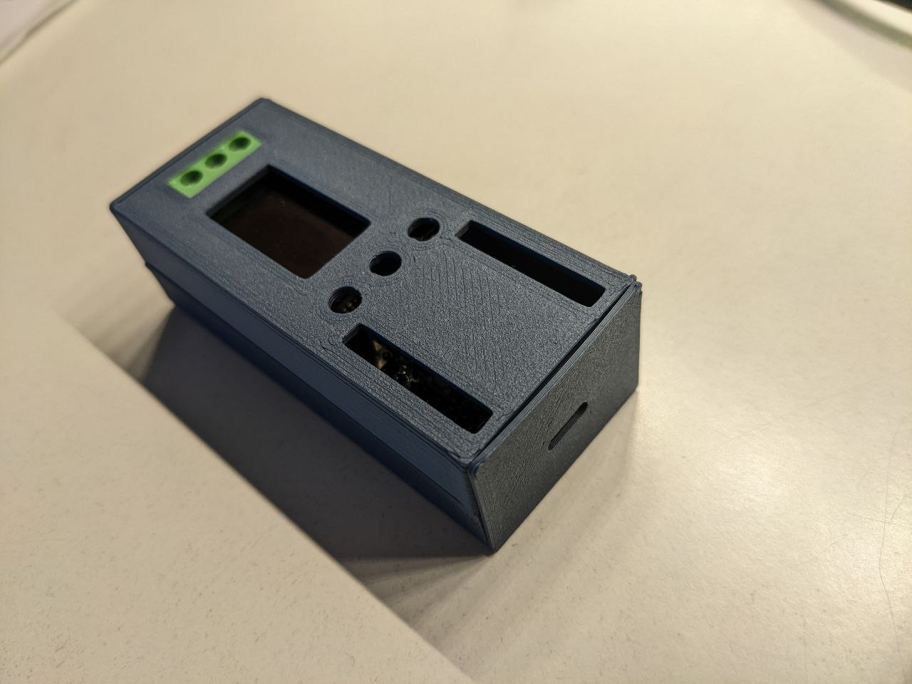
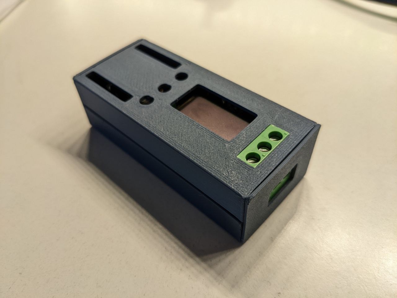
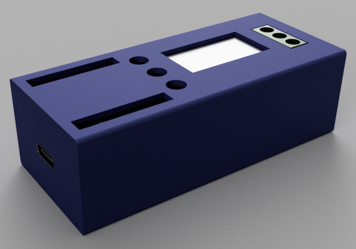
It looks already quite good but some dimensions are not correct. I also need to think about the different height of the components: headers, button, display.
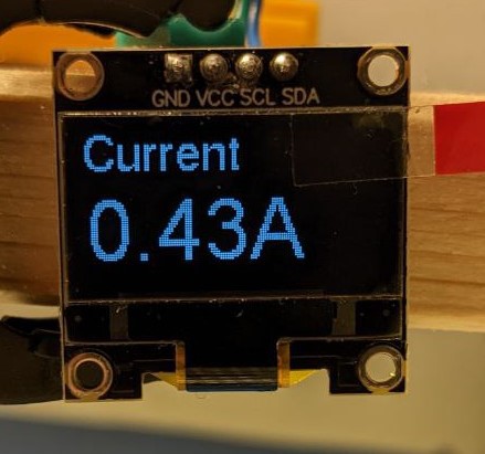
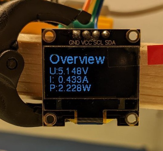
Well a really nice GUI on 2cm² is hard to realize but at least I could make everything good readable.
Due to the lack of different fonts and sizes in the default micropython library I searched for something easy to implement.
And I found it! Peter Hinch has written a really nice library in micropython hat is based on the official drivers for the frame buffer and the SSD1306 OLED display I use.
With some modifications in the code it just runs perfectly on my Pi Pico!
So, if you need a good GUI library that offers some fonts in different sizes, nice widgeds and is portable to many microcontrollers check his repo!
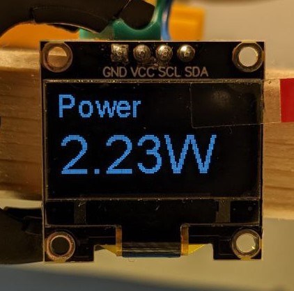
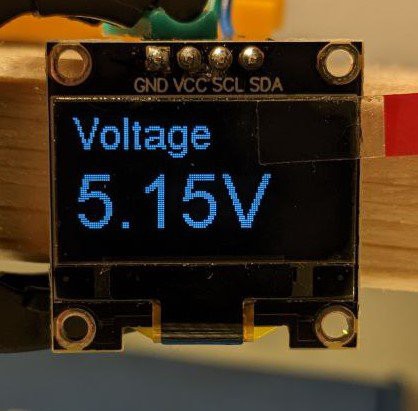
Now, here are some pictures of my 'pages'. With a push button it is possible to move from one 'page' to another.

 I disabled the THT components to see below the OLED display.
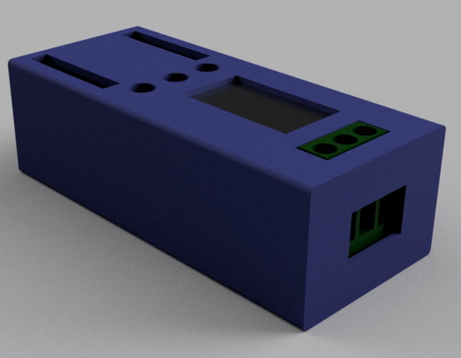
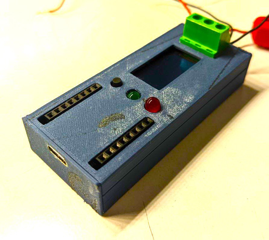 It came out a bit ugly due to a dirty printer bed...