Ruslan
-
Light Guide Prototyping
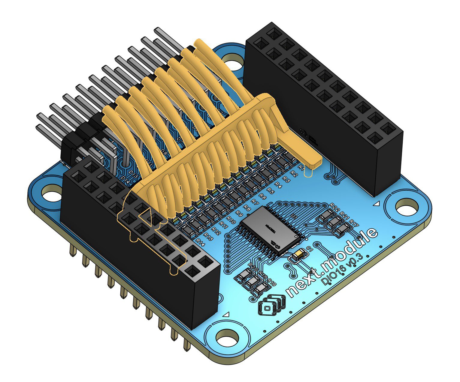
03/04/2026 at 12:43 • 0 commentsThe idea is to redirect light from the module’s onboard LEDs to the front/back surface above the connector.
![]()
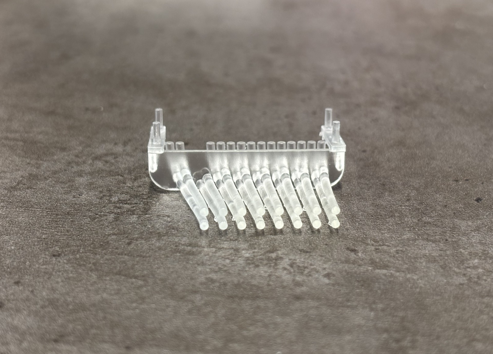
The first prototype focused on the most complex configuration: the light guide for the DIO16 board. It consists of 16 separate tubes diverging from a single row of 16 LEDs to form two rows of indicator points above the connector. On this board, the four rightmost connector pins are ground, so the light guides must be curved to align the indicators with the corresponding signal pins.
![]()
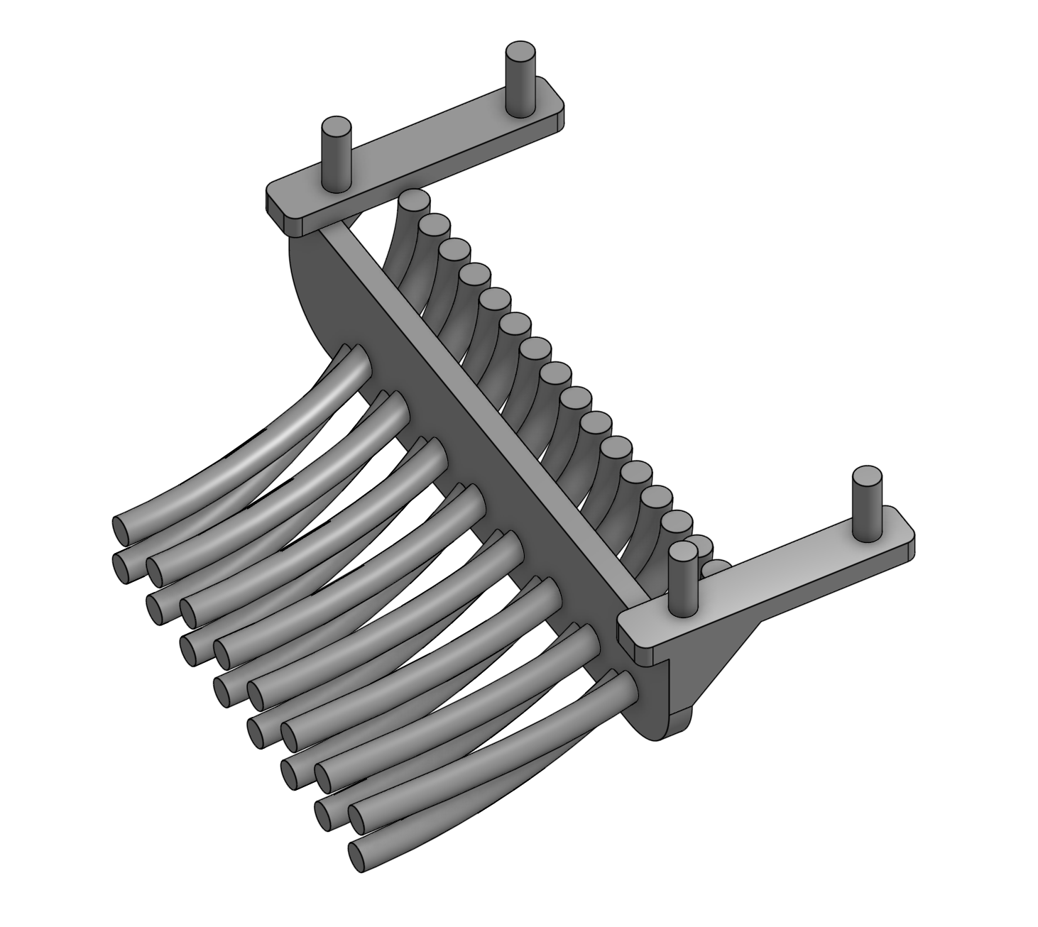
The model was designed for simplicity. The PCB 3D model was exported from EasyEDA and imported into OnShape. Splines were drawn from each LED to its target point above the connector, and 1.5 mm diameter tubes were extruded along these curves. The tubes are connected by a 1 mm thick vertical wall, which fits into four mounting holes on the PCB for stability.
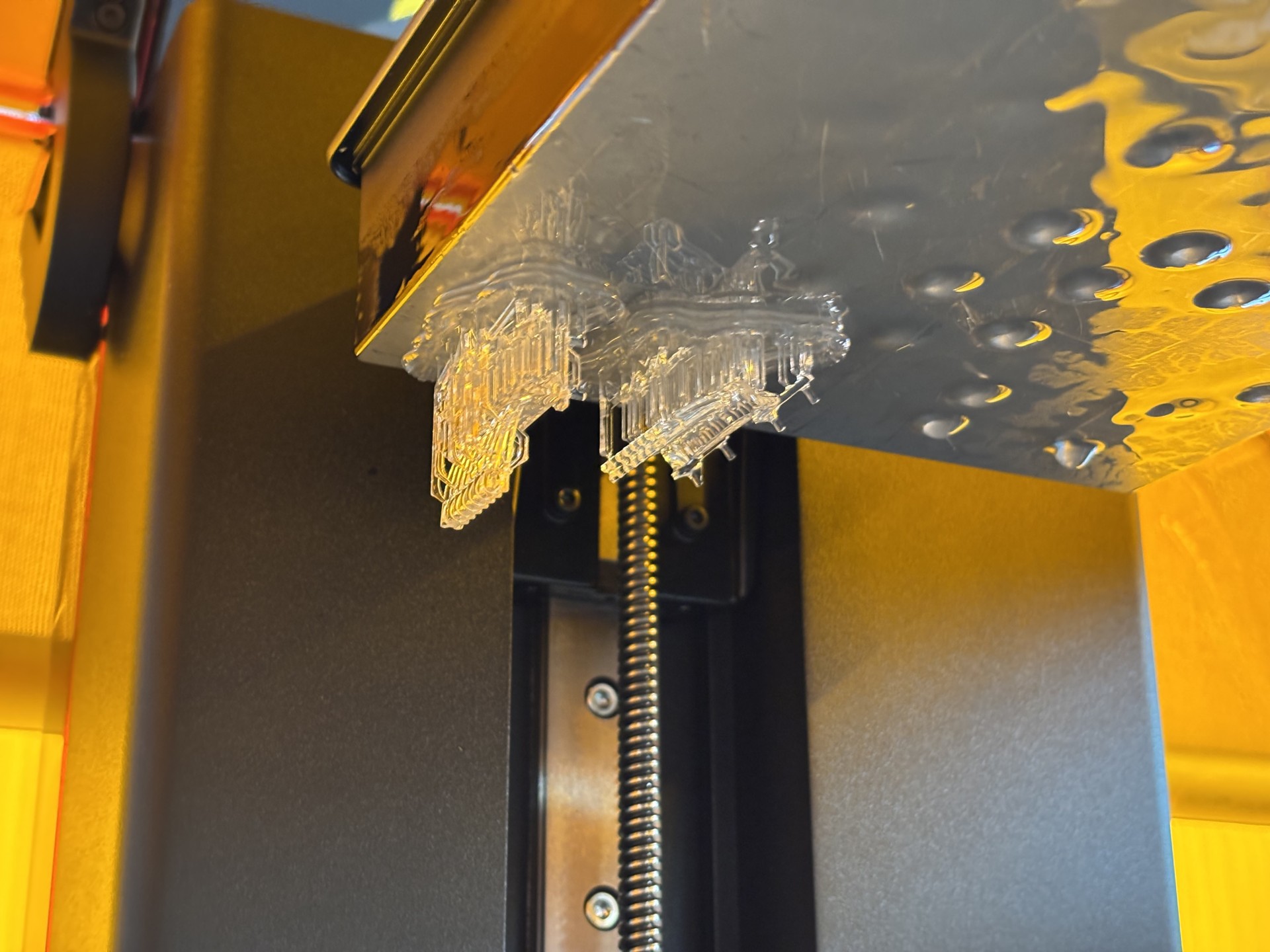
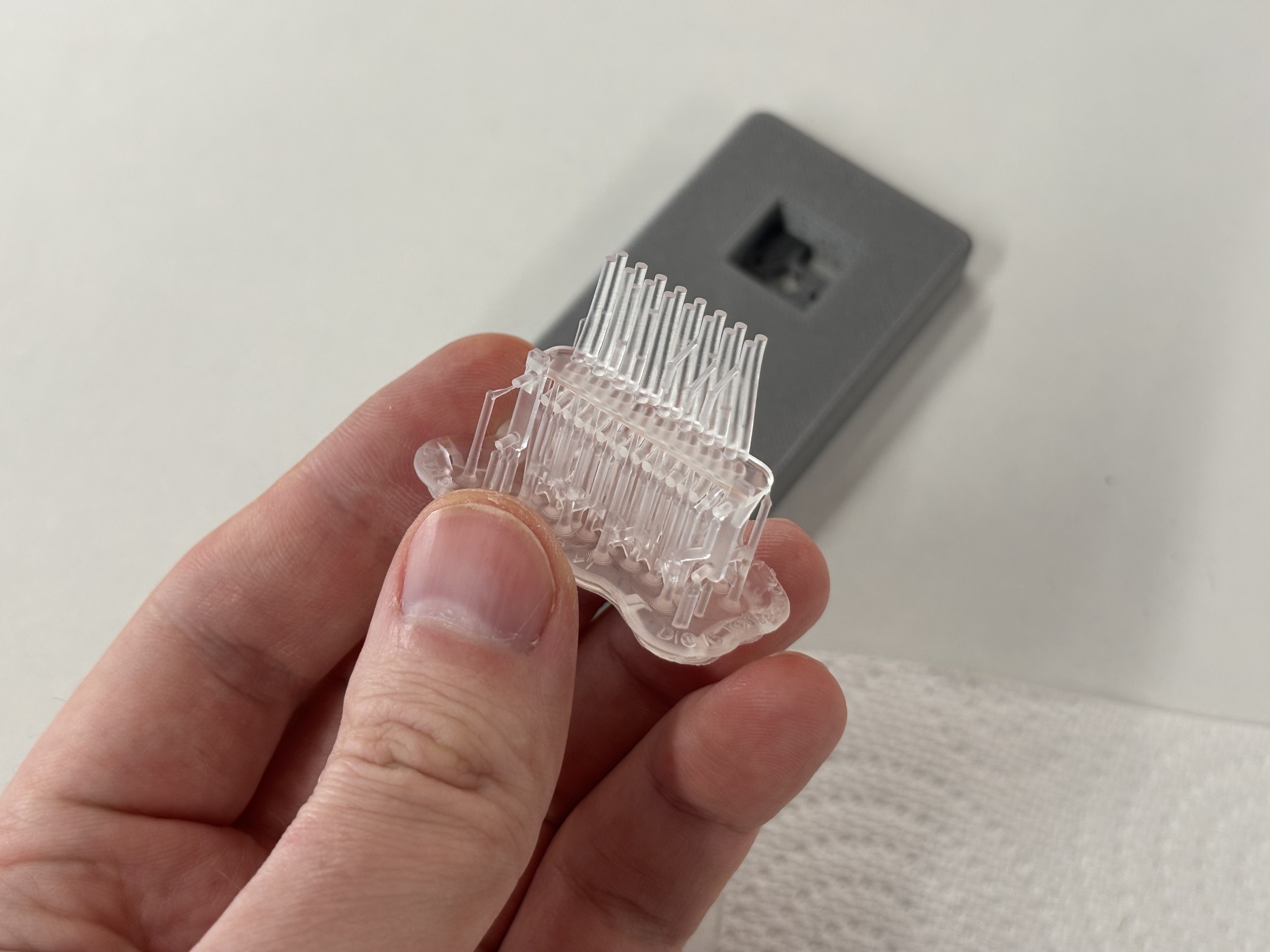
The light guide was printed in Formlabs Clear Resin V4.
![]()
![]()
After UV curing, the part became slightly cloudy and yellowed.
![]()
During the first print, two tubes were broken while removing supports.
![]()
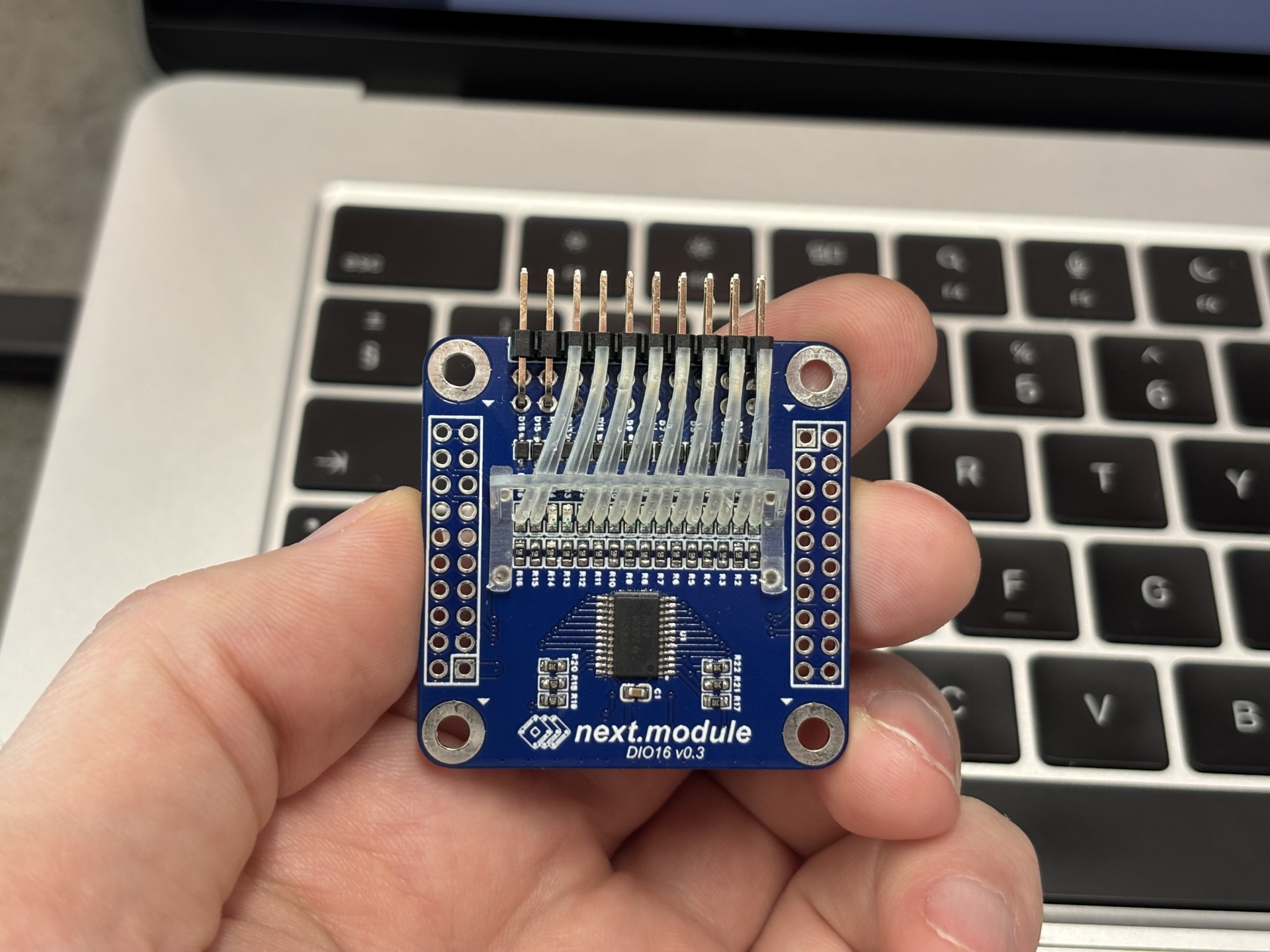
Dimensional accuracy was preserved, and the part positions precisely on the board.
![]()
![]()
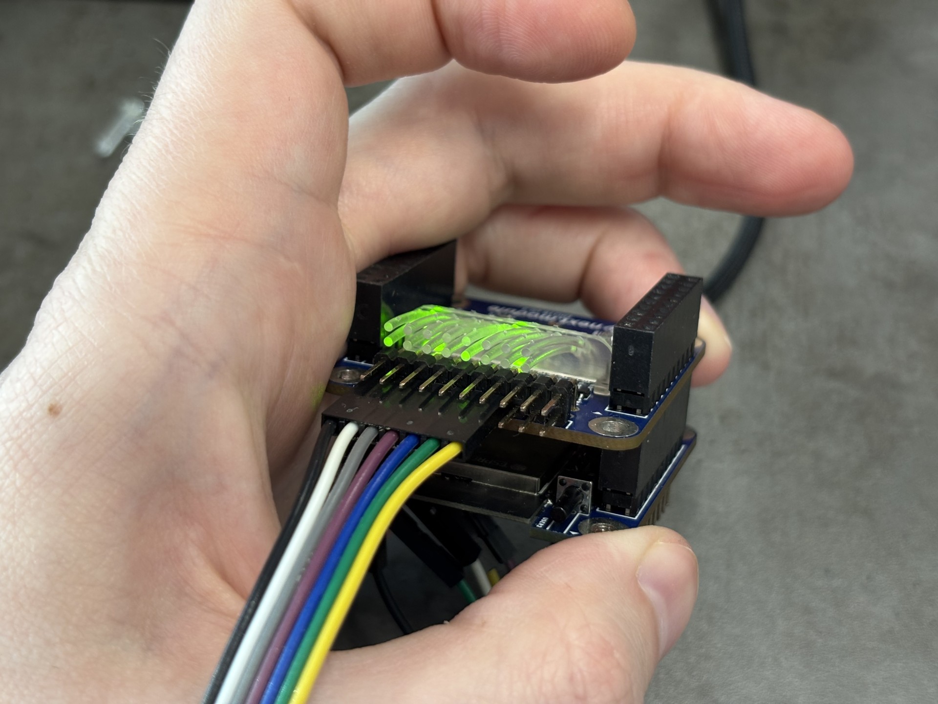
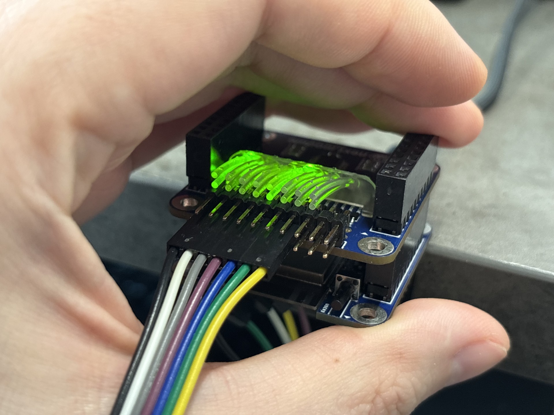
Performance is mixed. Light from adjacent columns is clearly distinguishable, but light from paired LEDs in the same column mixes significantly.
![]()
![]()
The main cause is the close spacing of the tubes near the connecting wall. Increasing the distance between them and using brighter LEDs could improve visibility.
The material is heat-resistant, so soldering the light guide to the PCB is not possible. Additionally, this complex geometry is only suitable for 3D printing—molding is not feasible. Future development requires simplifying the design, redistributing LEDs on the board, or considering a separate indicator PCB. -
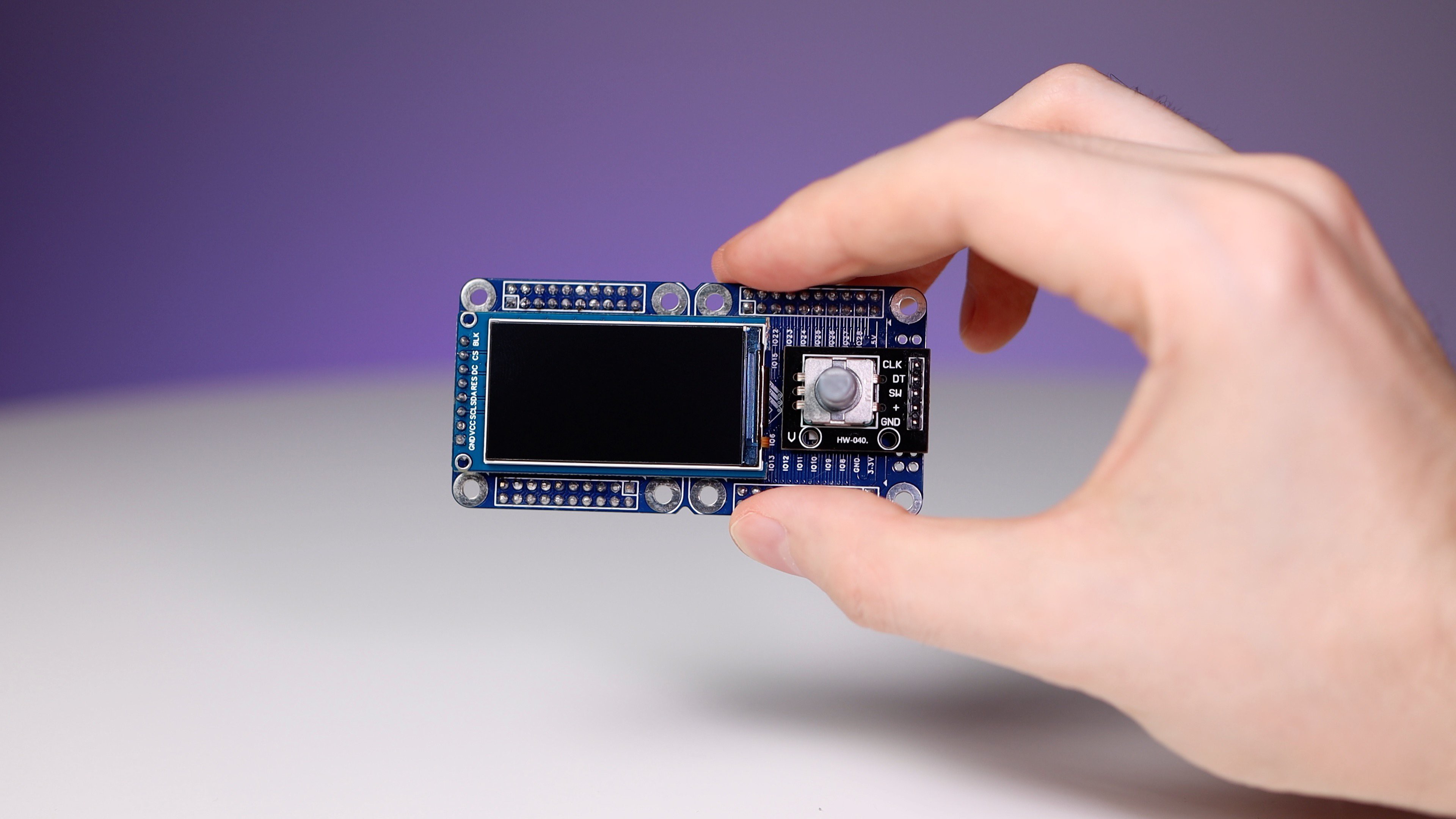
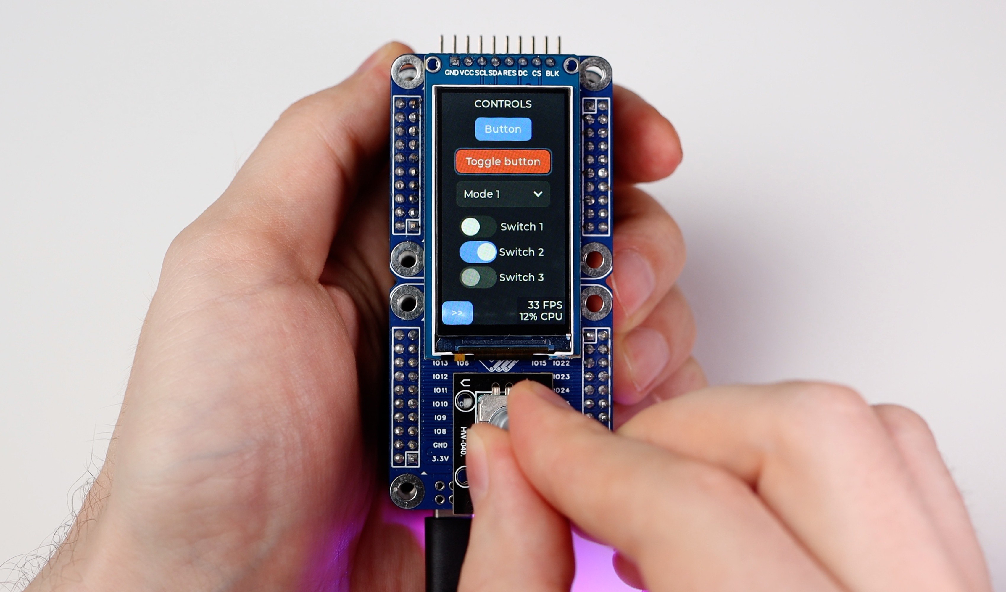
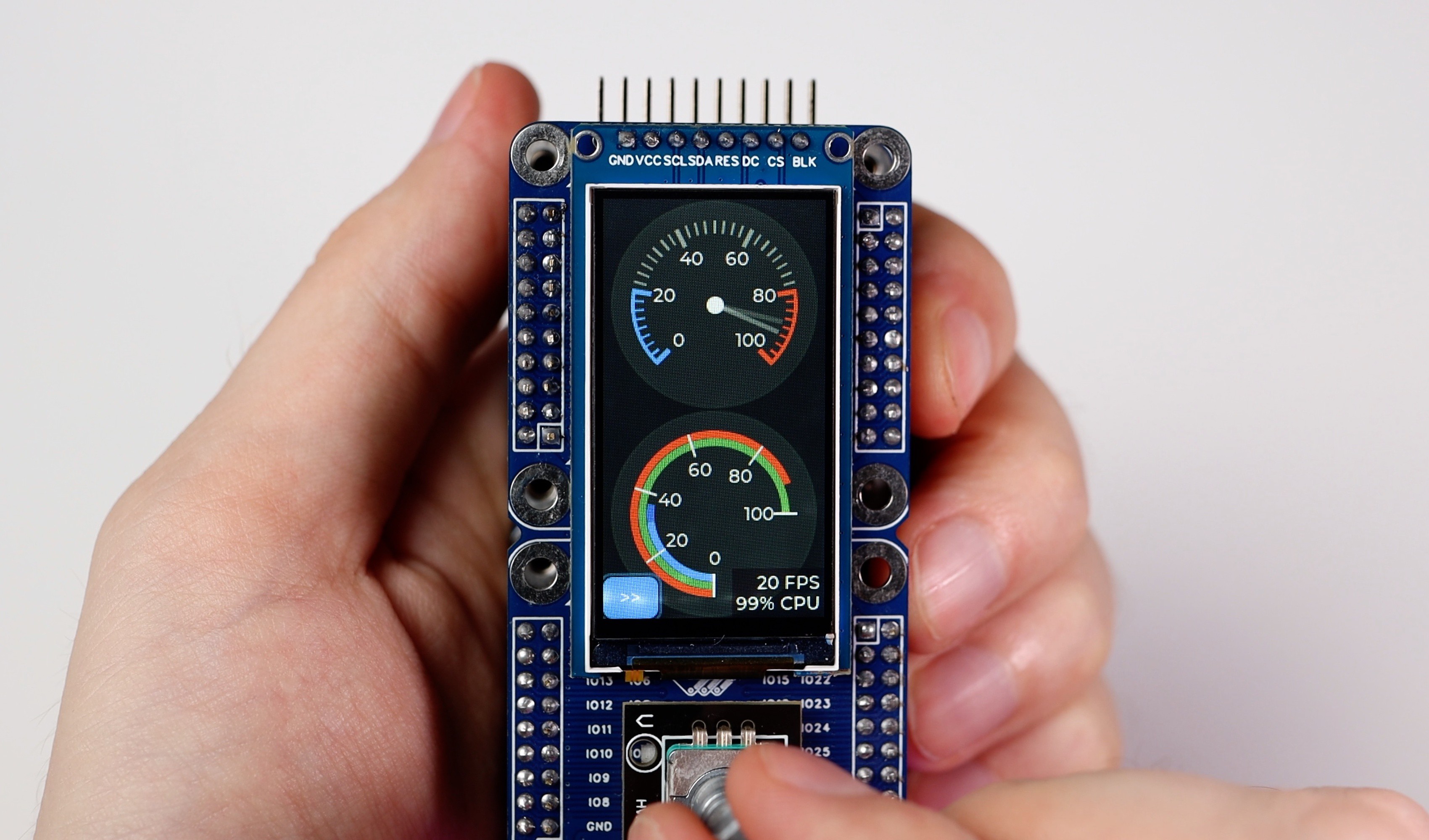
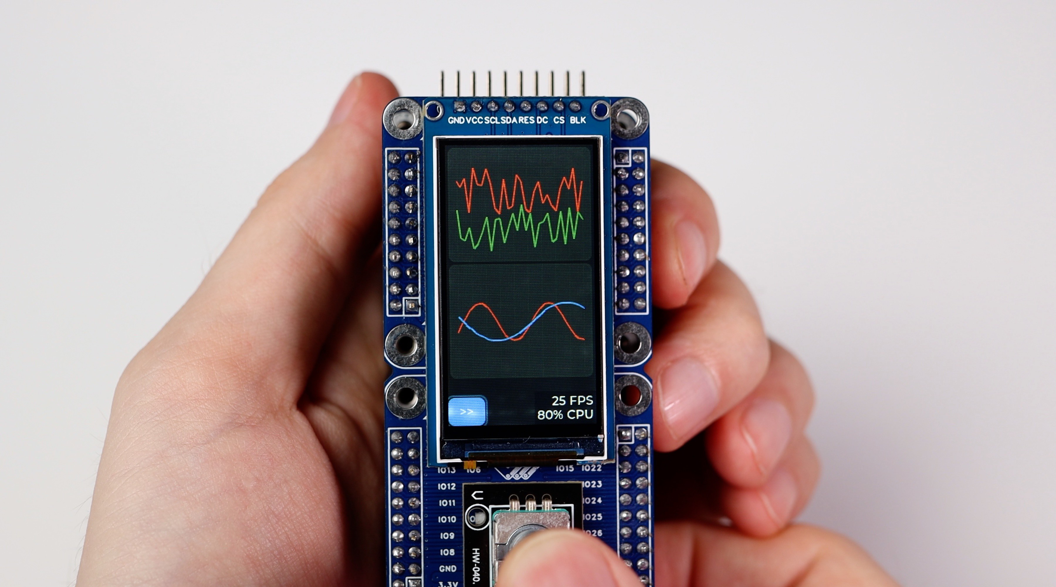
2-unit module with an IPS display and encoder
08/25/2024 at 13:10 • 0 commentsThis is a prototype of a 2-unit module with a display and an encoder for the next.module framework. It is assembled from:
- next.module HUB 1x2
- IPS display 170x320 1.9’ (ST7789)
- KY-040 encoder
The prototype allows me to experiment with the LVGL GUI library and understand how I want to see the final module on the factory PCB![]()
![]()
![]()
![]()
![]()
![]()
-
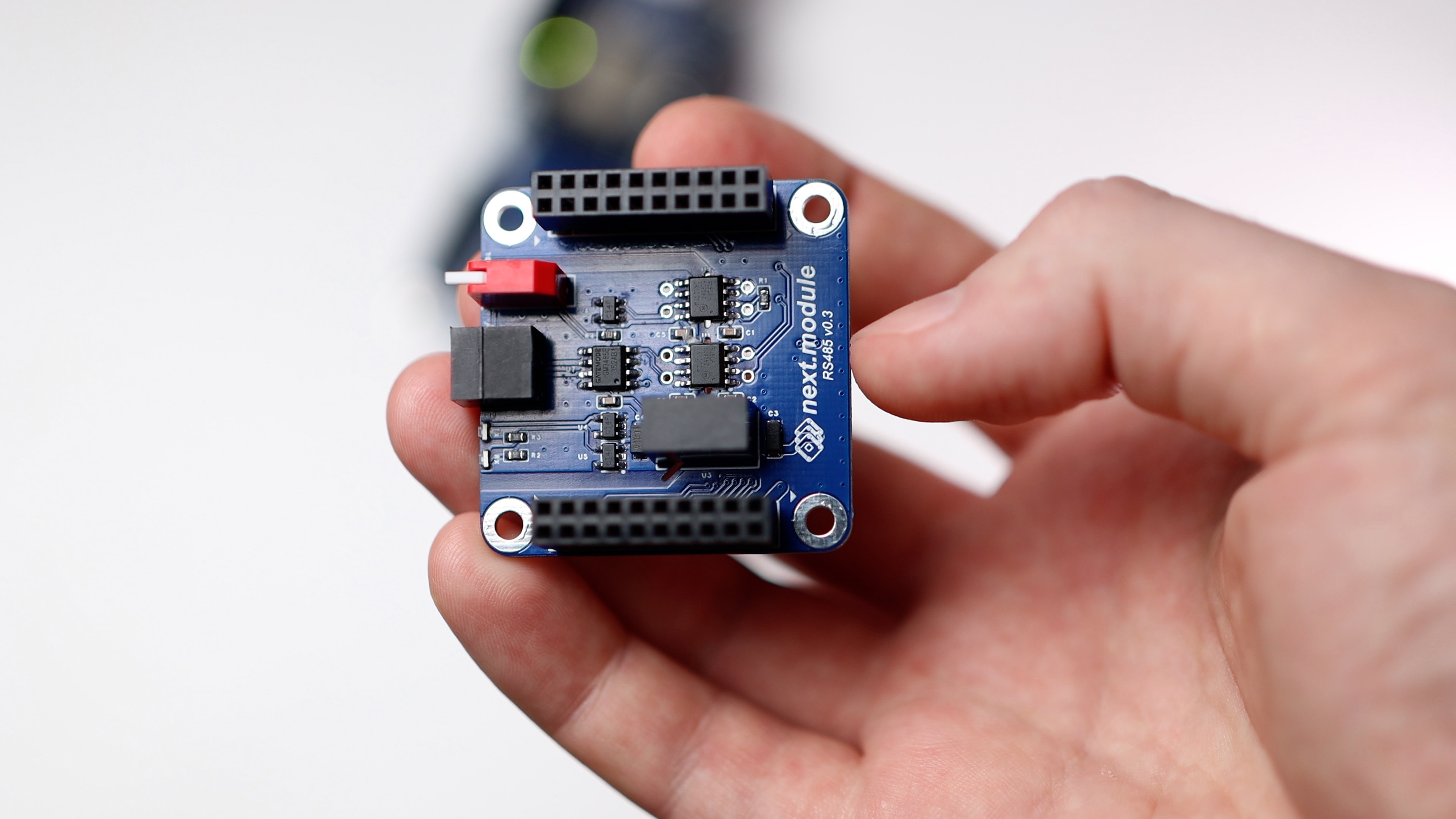
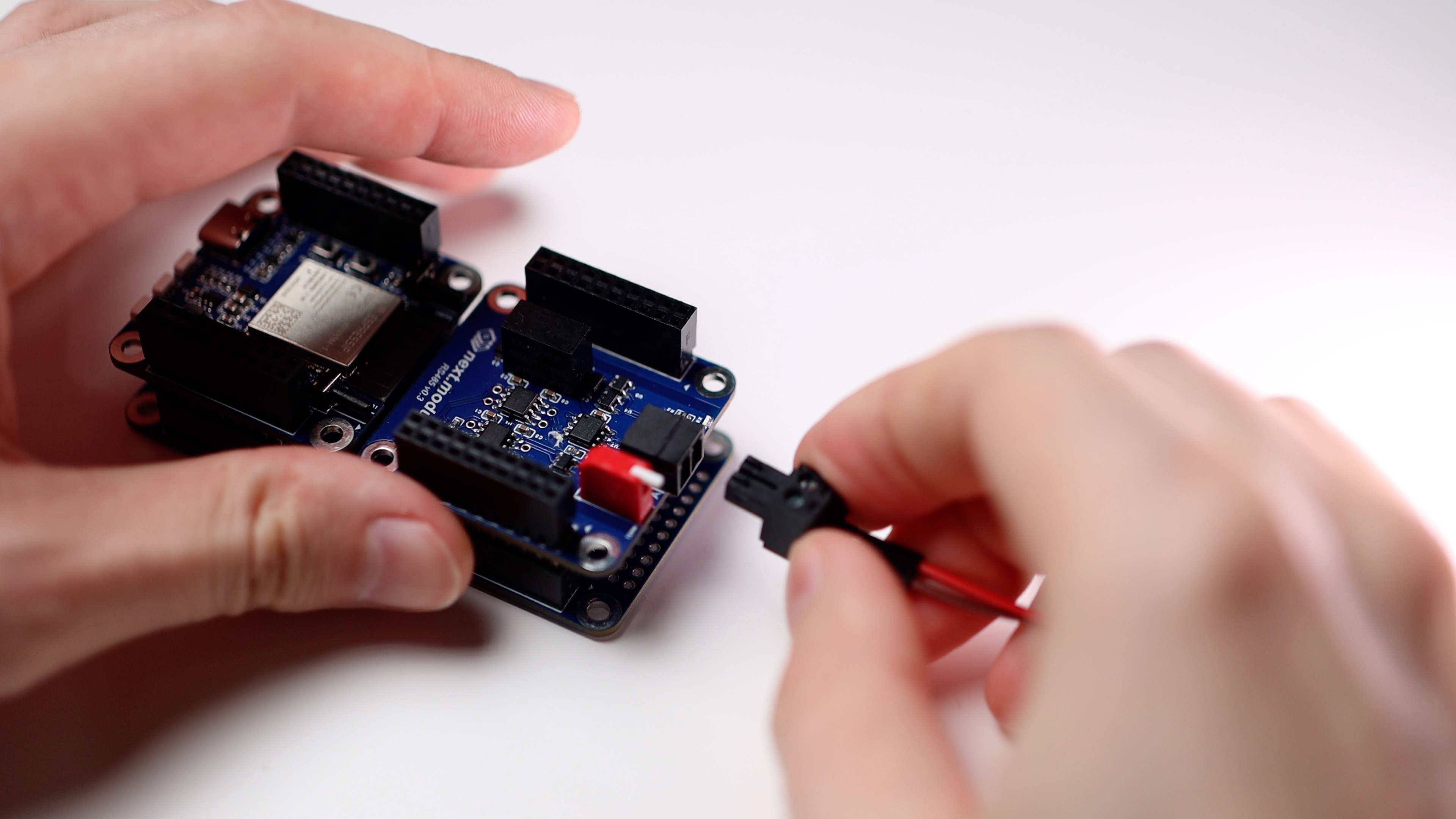
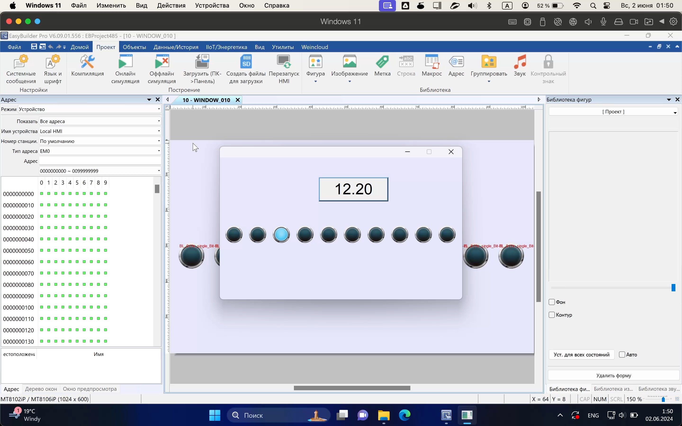
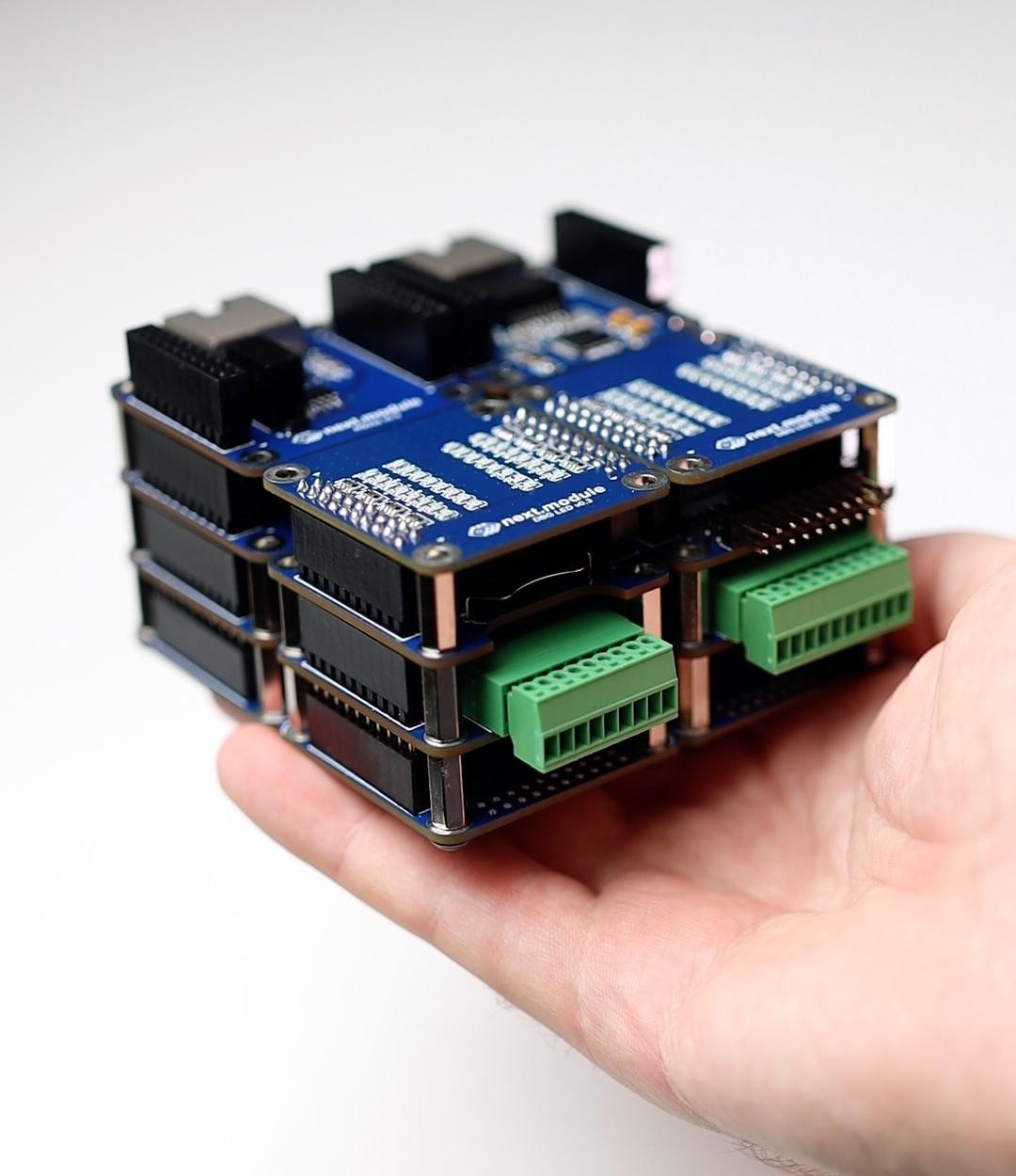
next.module: RS485 module tested
06/18/2024 at 07:00 • 0 commentsThe RS485 module was tested up to a speed of 115.2 Kbps. I used the MODBUS RTU protocol and EasyBuilder Pro to test it.
One thing to note about the module is that it inverts the DE signal (it needs to switch the RS485 transceiver to transmission mode). This inversion is necessary due to the peculiarities of the galvanic isolator (2Pai Semi π121U31). When power is applied to the device and the DE pin has not yet been initialized, without an inverter, the transceiver will immediately turn on the transmitter (logic 1 will appear at the output of the isolator).
Хэштег#nextmodule Хэштег#rs485 Хэштег#rs422 Хэштег#module Хэштег#industrial Хэштег#plc Хэштег#automation Хэштег#iot Хэштег#devboard![]()
![]()
![]()
![]()
![]()
![]()
-
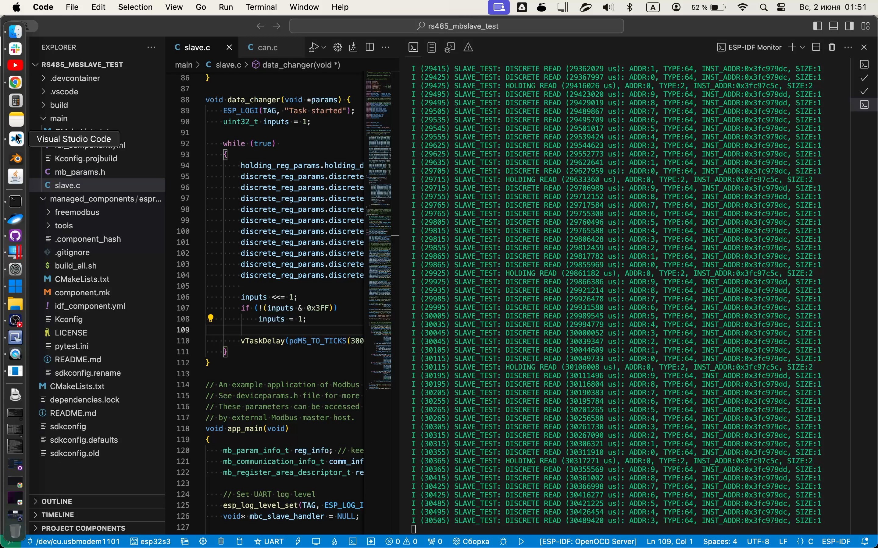
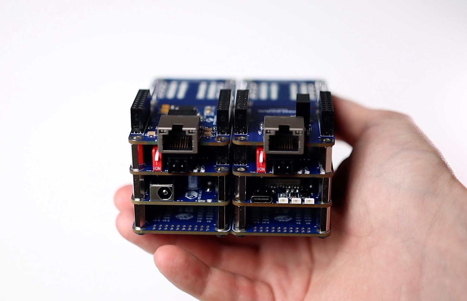
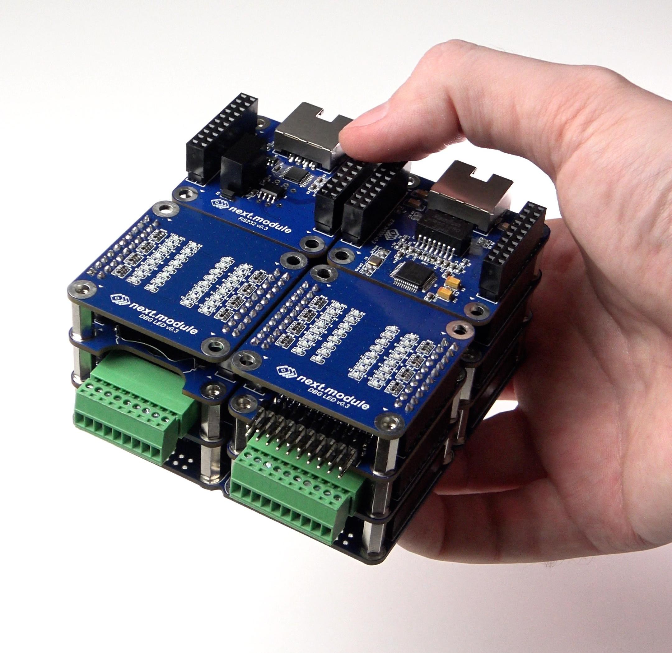
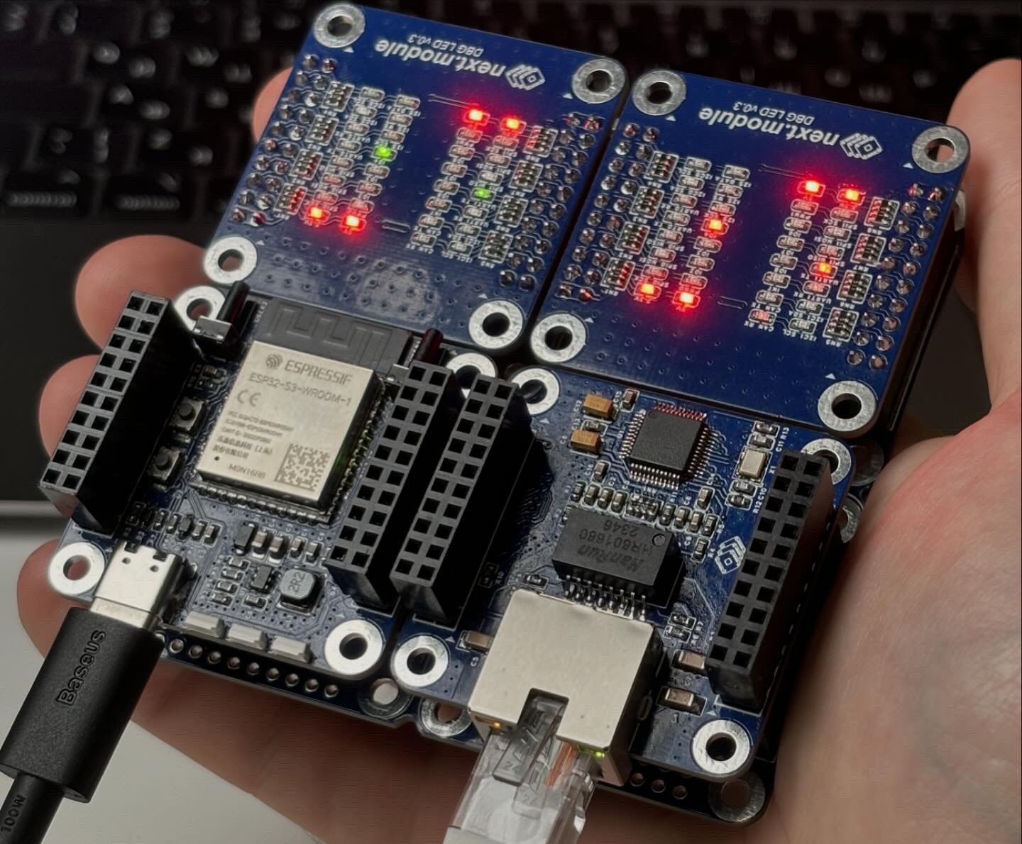
12 modules in one device!
06/10/2024 at 07:40 • 0 comments12 modules in one device:
1 x CPU ESP32S3
1 x PSU DC
1 x ETH W5500
1 x 8DI-ISO
1 x 8DO
1 x 16DIO
1 x CAN
1 x RS485
1 x RS232
1 x RTC
2 x DBG LED
Size: 54.5 x 85.2 x 85.2 mm![]()
![]()
![]()
![]()
![]()
-
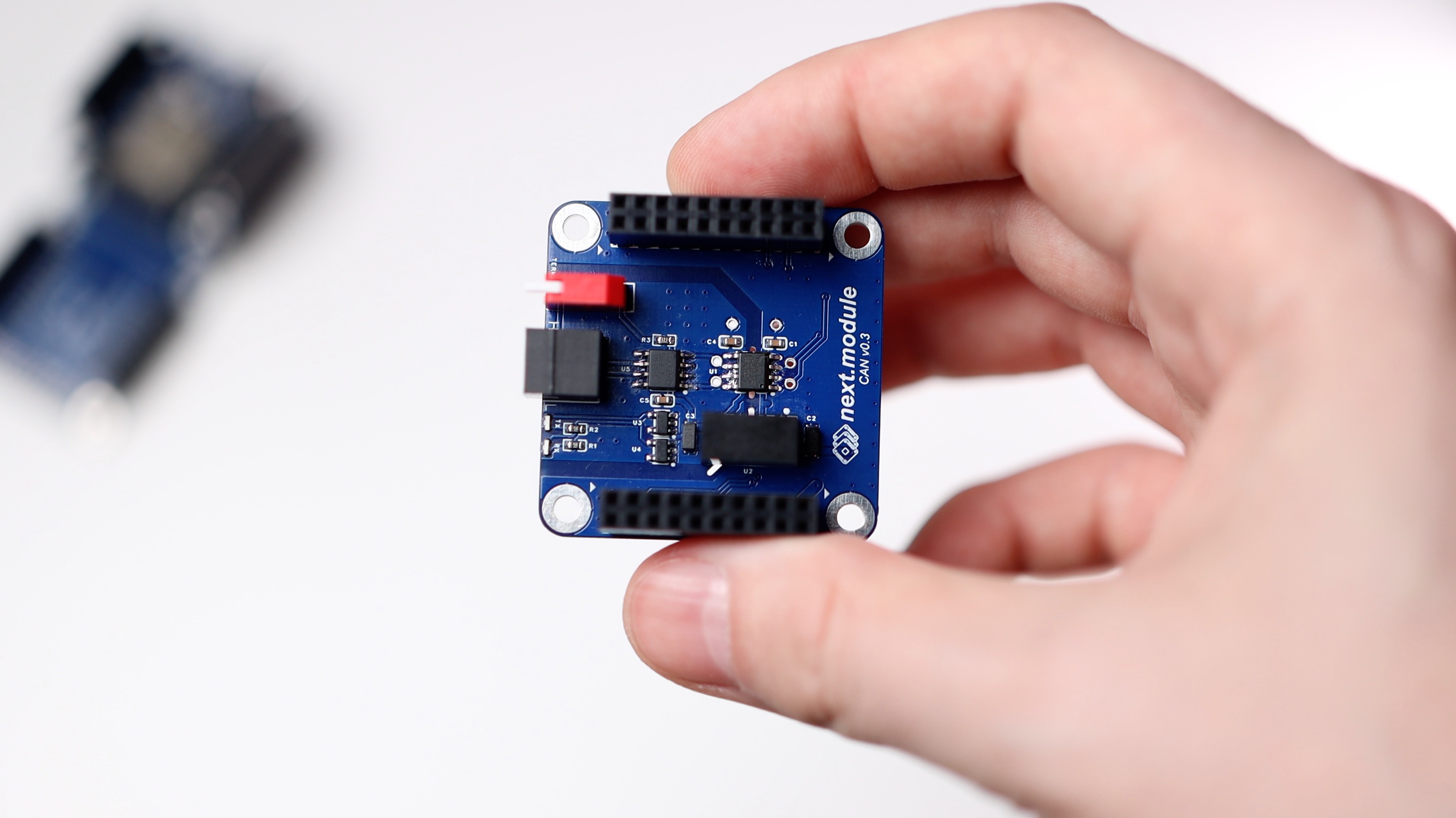
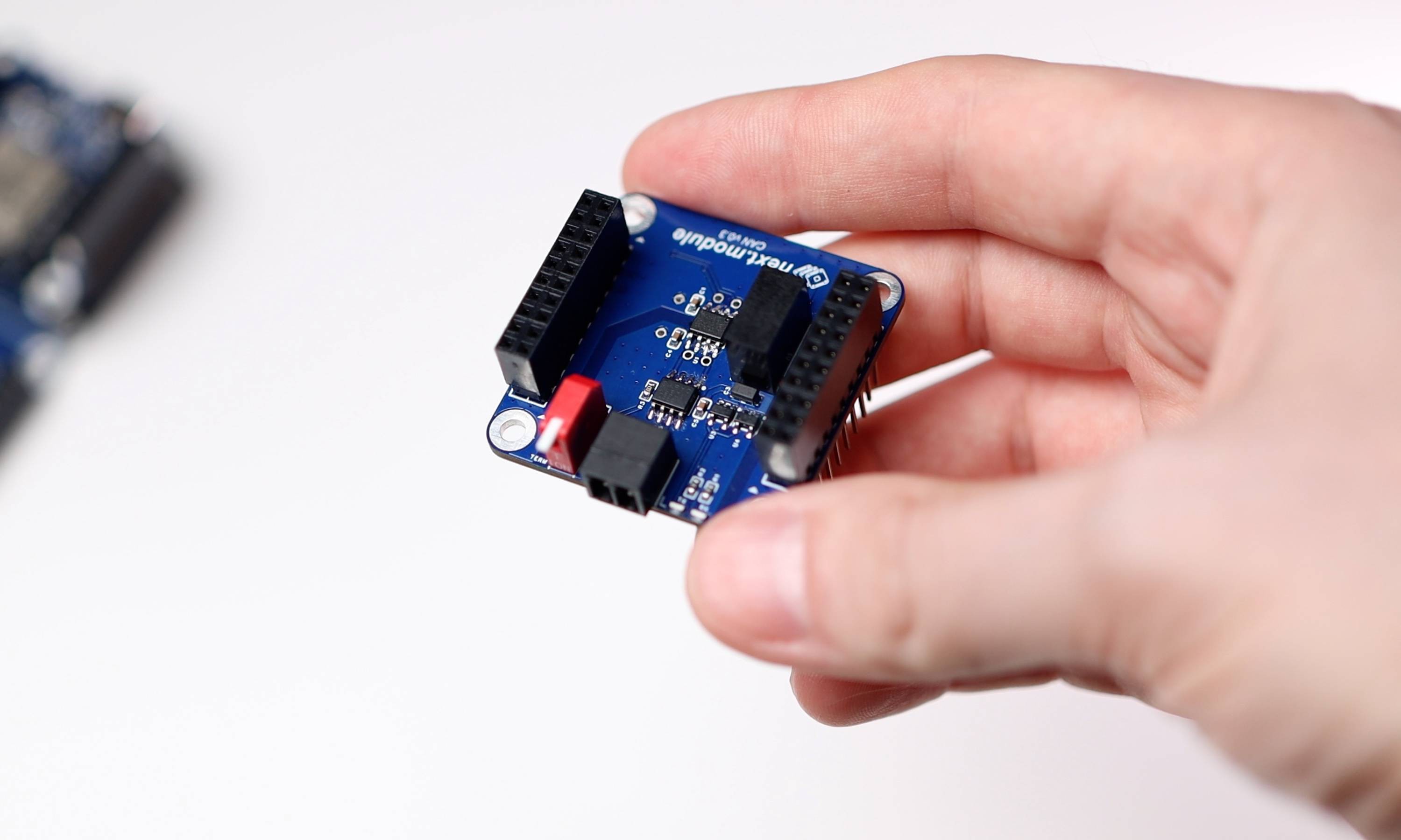
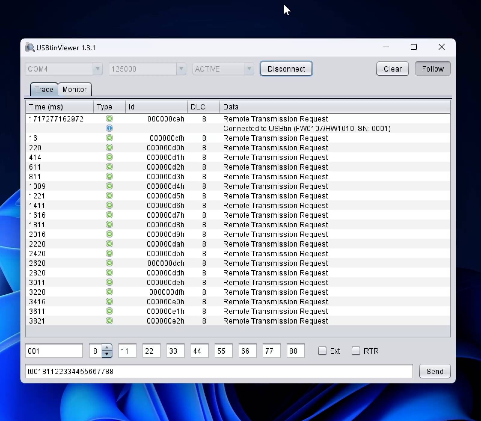
next.module: CAN module tested
06/04/2024 at 14:59 • 0 commentsCAN module has been successfully tested! In both versions with and without galvanic isolation.
It has been tested at speeds ranging from 10 Kbps to 1 Mbps. The most important thing is that the capacitive galvanic isolator from the Chinese company 2Pay Semi performed well, I had doubts about it.
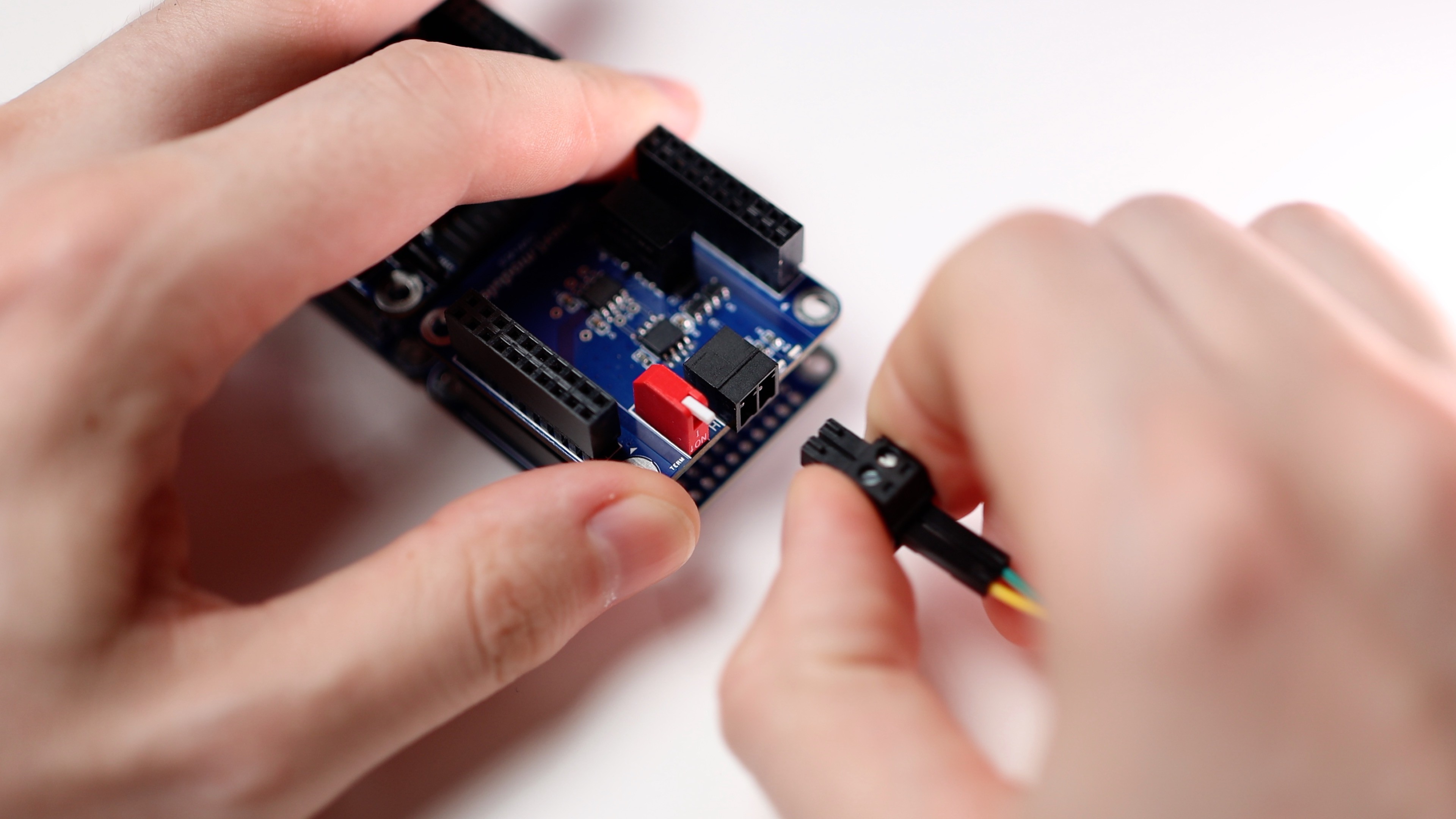
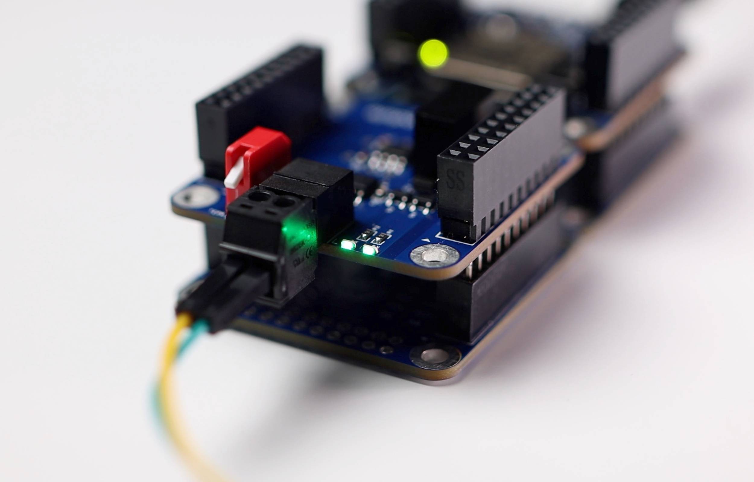
In fact, I had to tinker with the testing. I've been testing the communication between two ESP32S3 through CAN. And sometimes everything worked well, but sometimes frames with an empty body were accepted. I spent 2 evenings, but I still didn't understand what the problem was.
It turned out that the problem was with the firmware. When sending a frame, I forgot to set the Remote Transmission Request (RTR) flag in the twai_message_t structure on the stack. This flag took a random value when I flashed the ESP32 switching the CAN speed. As a result, reception worked well at some speeds (RTR=0), and an empty frame body arrived at some speeds (RTR=1).#nextmodule #can #canbus #module #automotive #plc #automation #iot
![]()
![]()
![]()
![]()
![]()
![]()
-
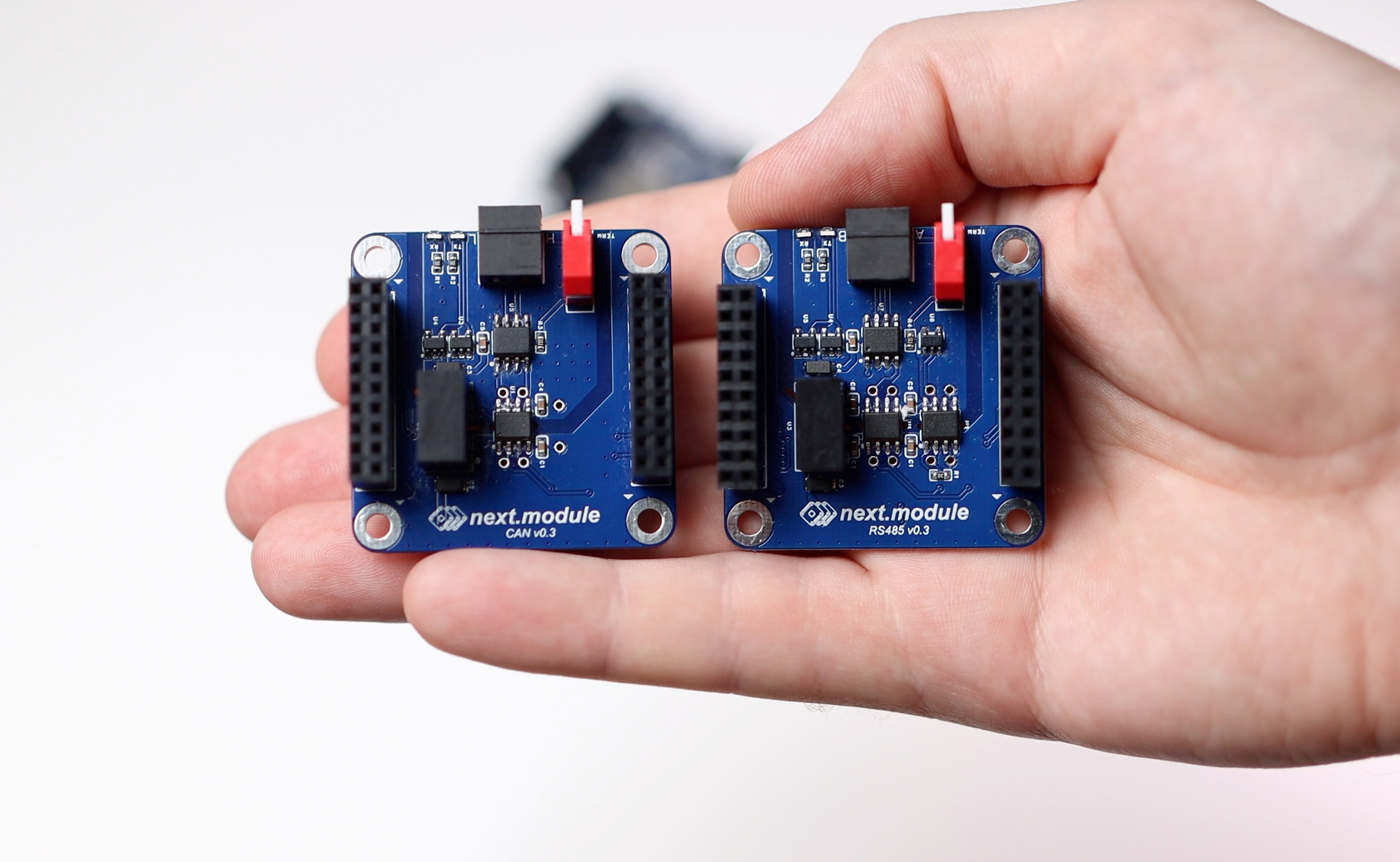
CAN and RS485 modules assembled
06/02/2024 at 13:01 • 0 comments![]()
-
Here are some next.module demo videos
05/31/2024 at 06:15 • 0 comments -
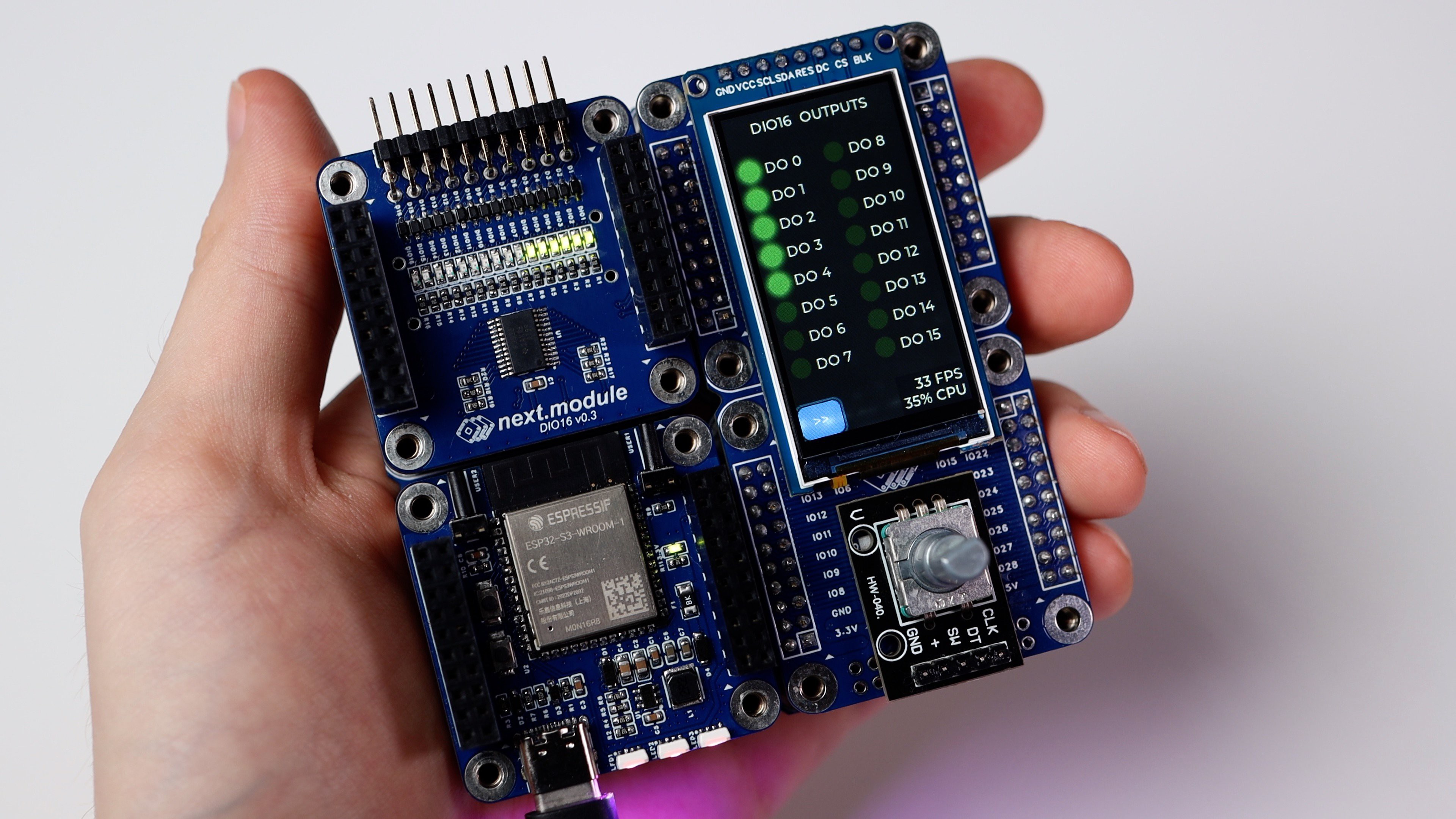
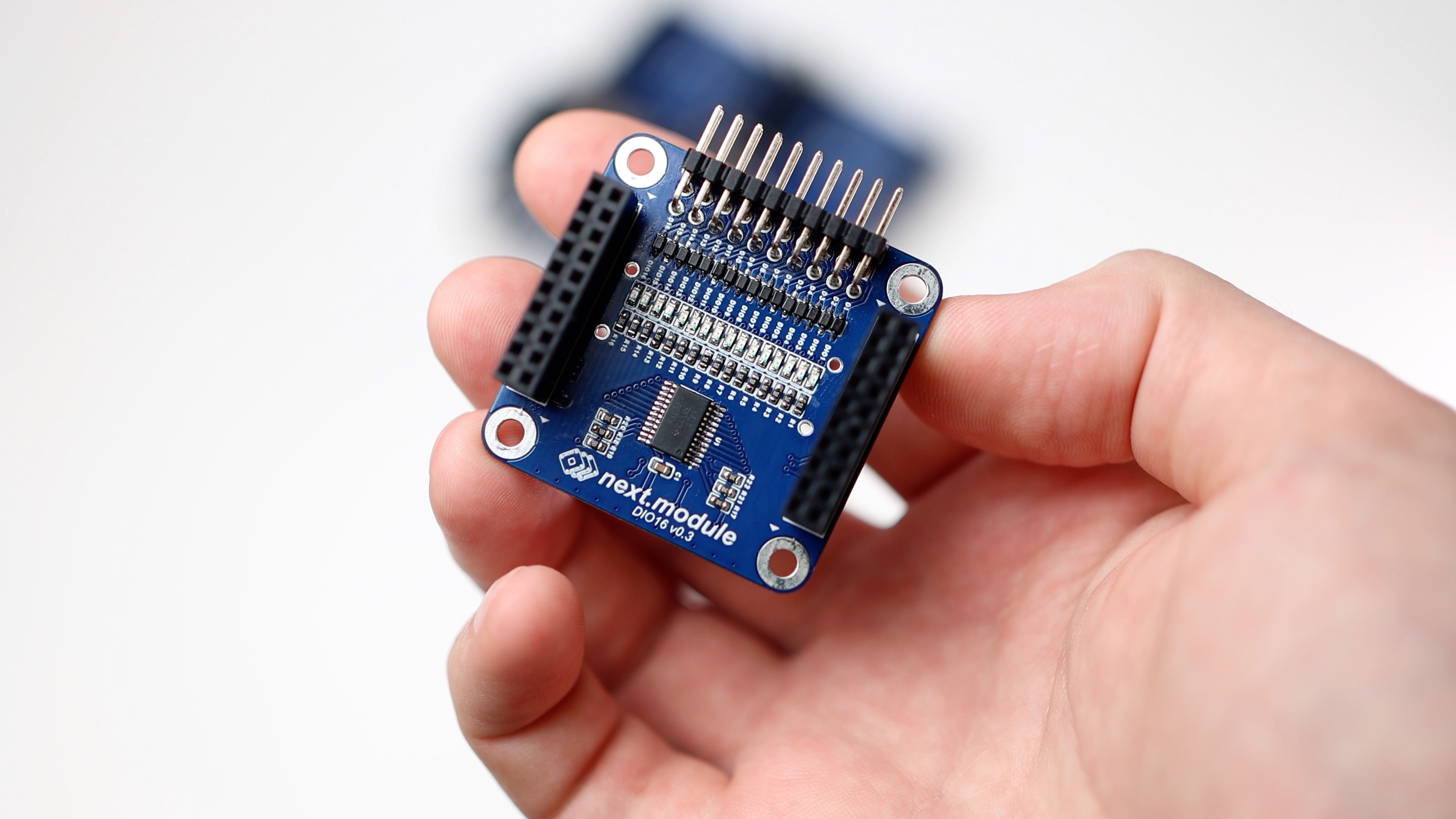
Digital IO modules testing
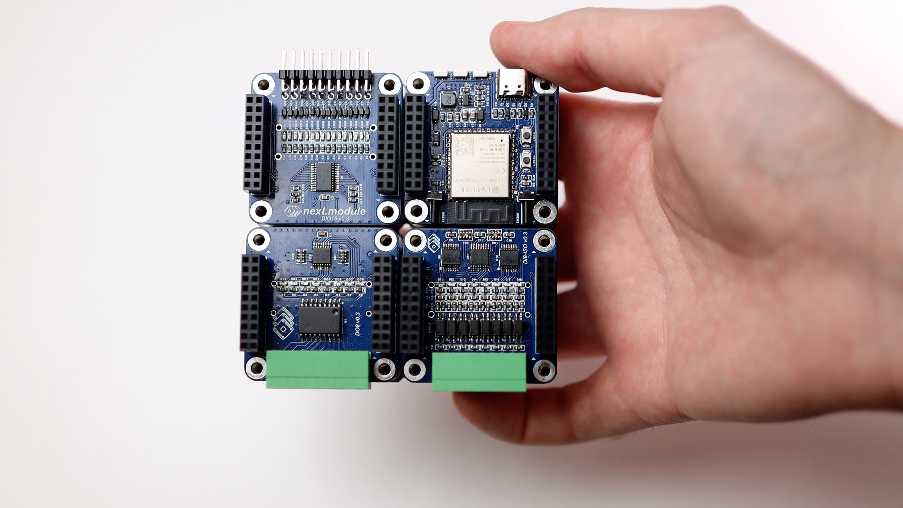
05/30/2024 at 07:00 • 0 commentsThe modules DI8-ISO (8 inputs), DO8 (8 outputs) and DIO16 (16 GPIOs) have been tested and they all work fine.
However, there are a few things that need to be fixed:
🟠 In DI8-ISO, I need to increase the resistance to limit the current through the optocouplers. Currently, it is 2K, and when a 24V input is applied, we get a current of 11 mA, resulting in heat dissipation of 250 mW on a resistor that is designed for only 100 mW. To trigger the input, it is sufficient to pass 1 mA through the optocoupler.
🟠 In DO8, I need to add a short circuit protection. General, group, or individual (I haven't decided yet).
![]()
![]()
![]()
![]()
![]()
![]()
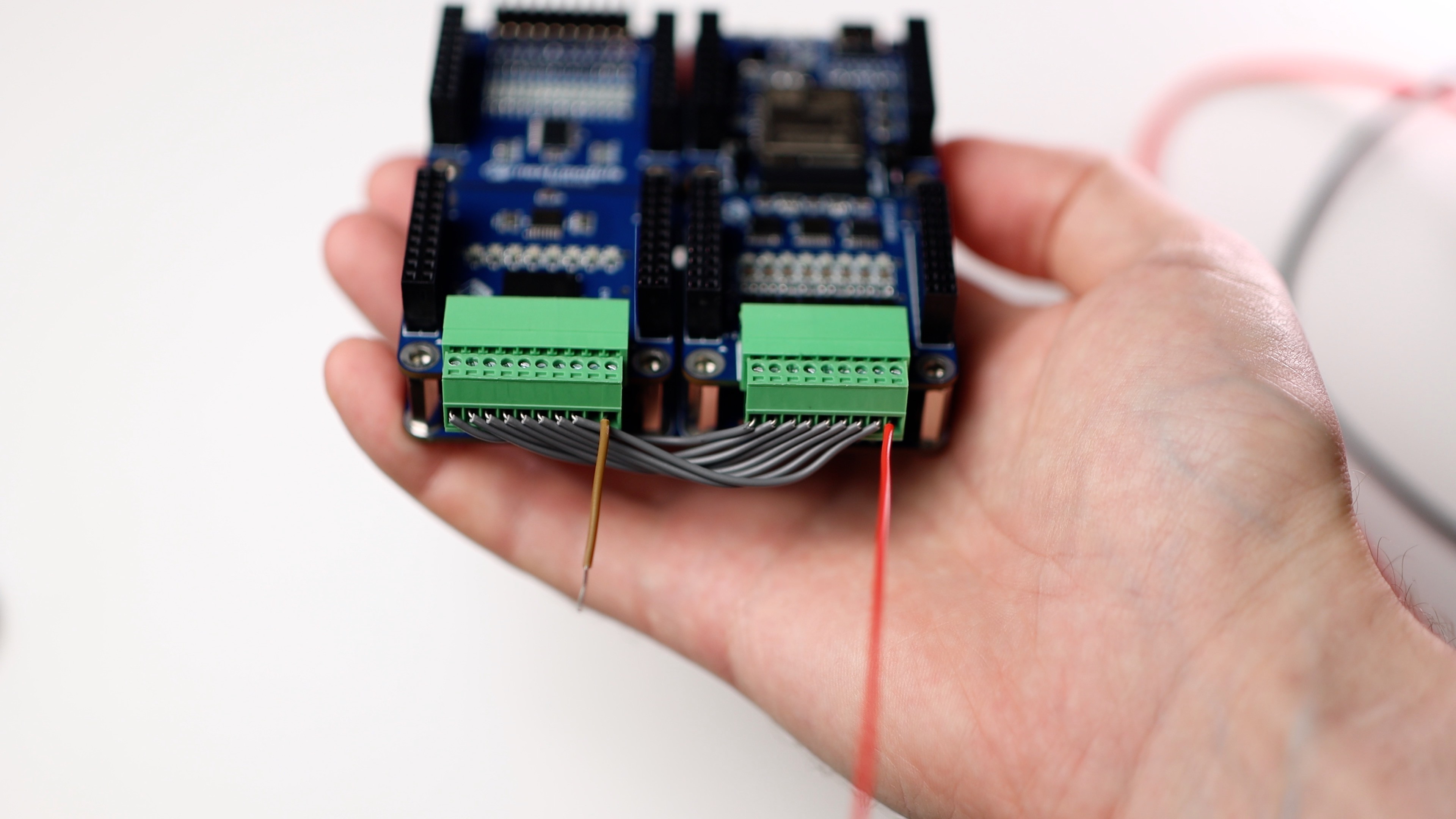
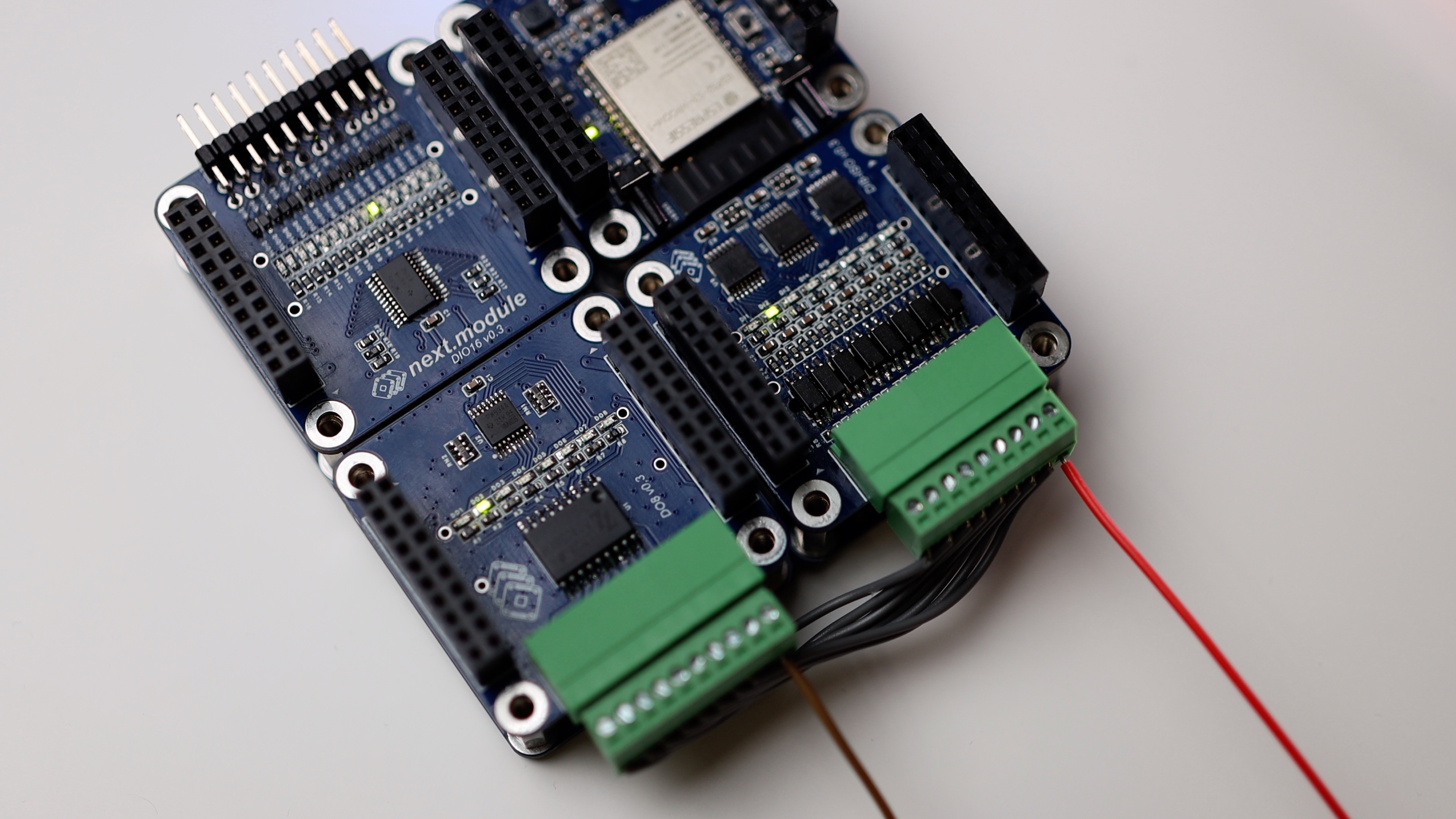
The inputs can be connected to the outputs directly. This requires a power supply to provide current through the optocouplers.
![]()
![]()
#nextmodule #digitalinputs #digitaloutputs #devboard #plc #module #esp32 #tca9534 #tca9535
-
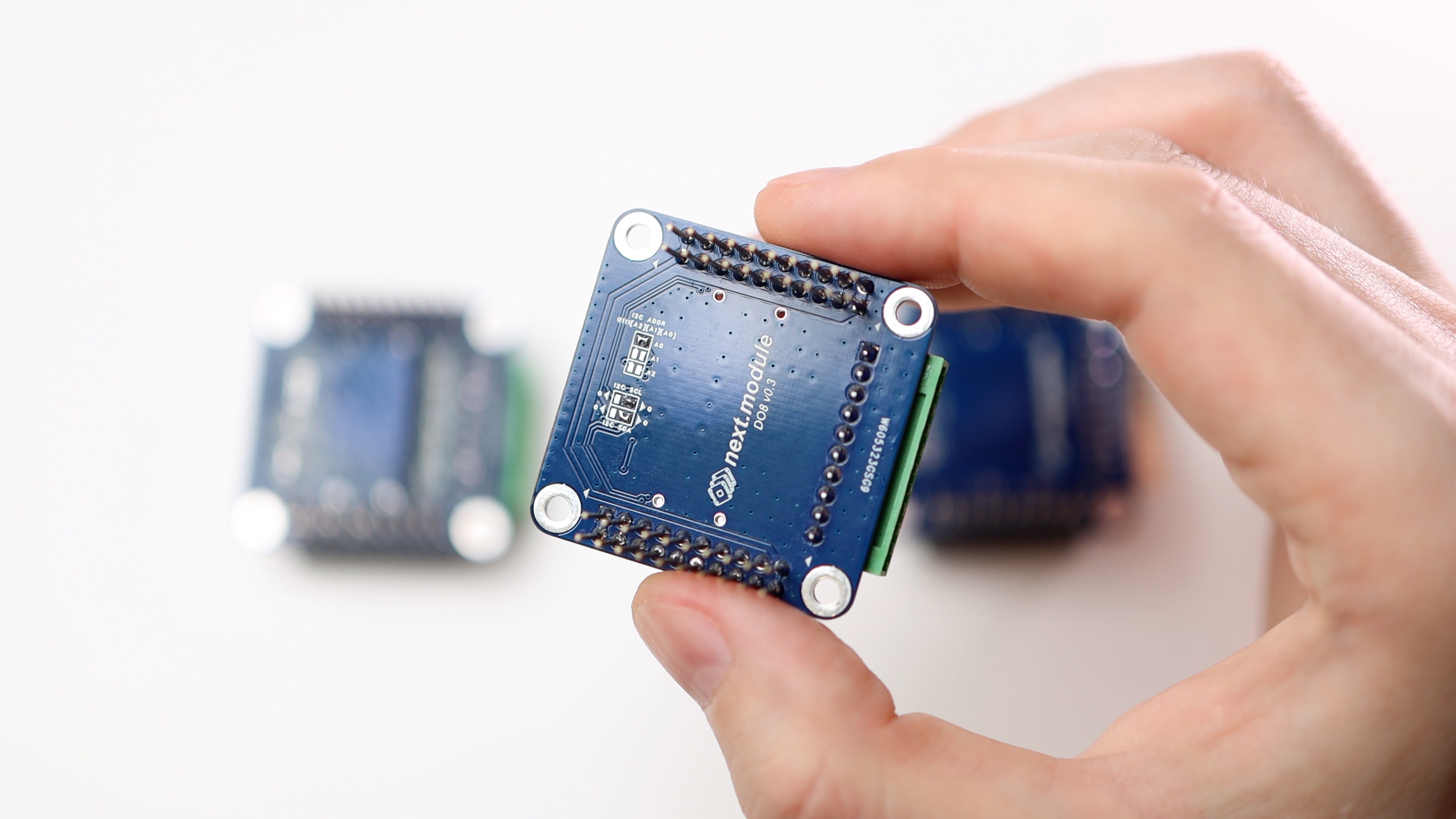
Connectors for DI8-ISO and DO8
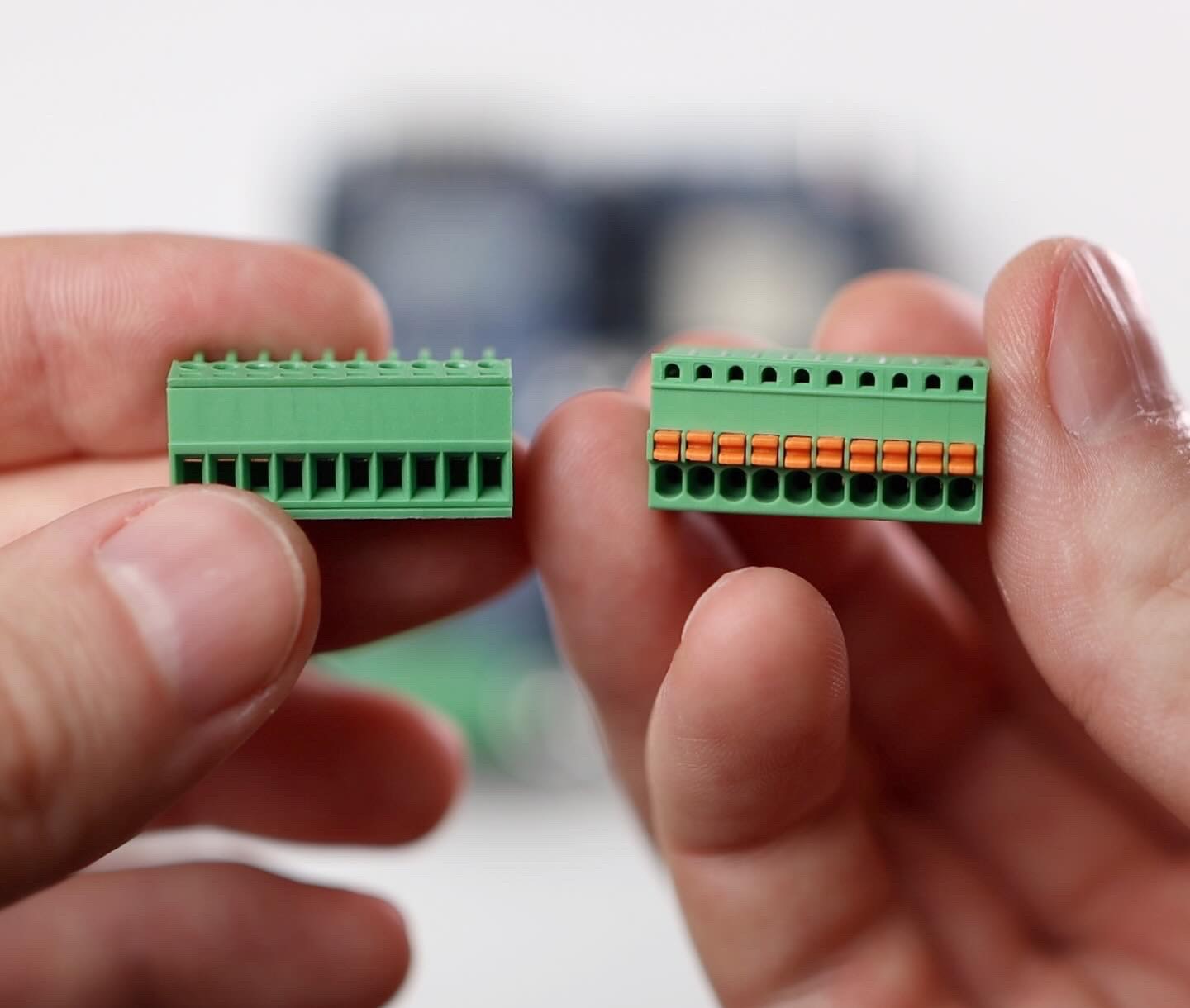
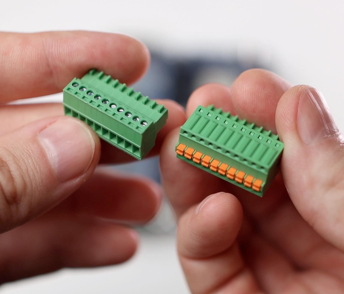
05/29/2024 at 19:05 • 0 commentsConnectors for DI8-ISO and DO8 modules may have different designs, such as screw terminals or spring terminals.
Spring terminals are larger and slightly more expensive, but they provide good contact over time and in vibration environments.
![]()
![]()
![]()
-
ETH W5500 module testing
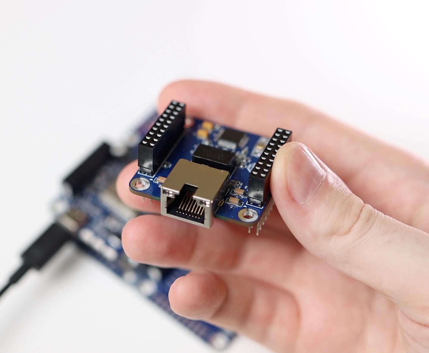
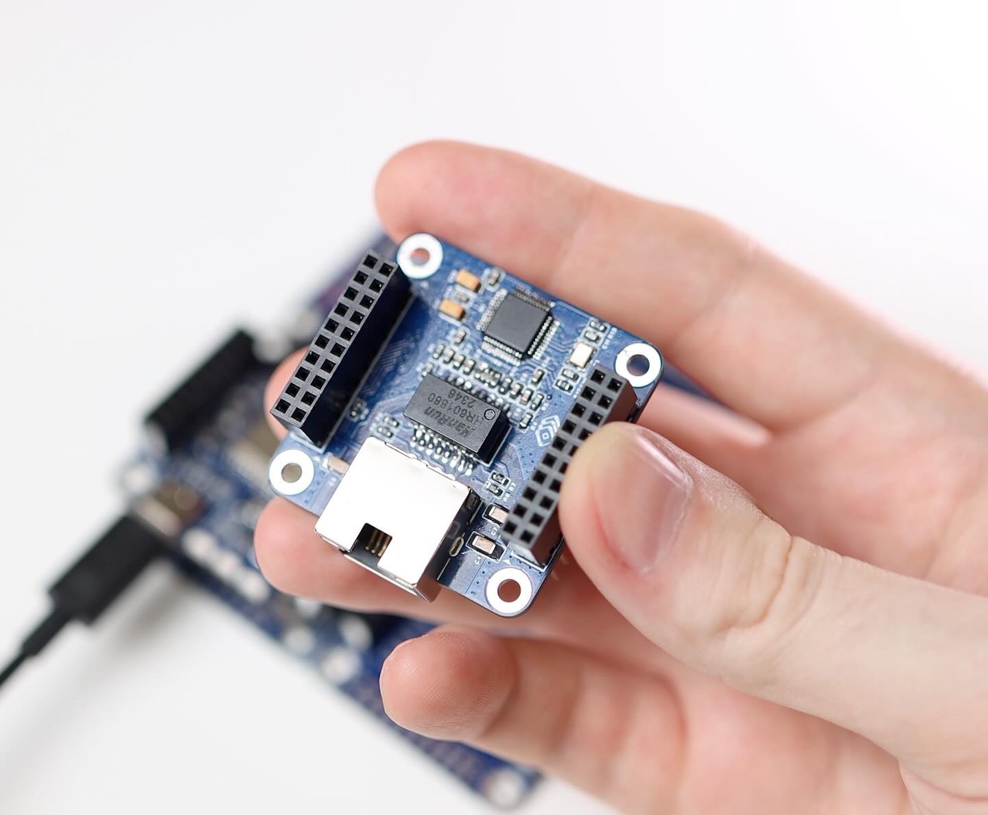
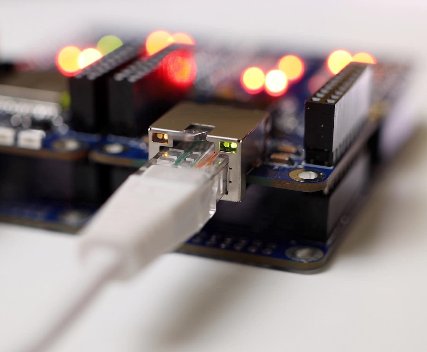
05/22/2024 at 09:20 • 0 commentsThe ETH W5500 module is working!
I was concerned about possible mistakes in the wiring of the chip on Ethernet side, but everything is ok.
There are 2 issues:
✅ I forgot to add a 1 Mohm resistor that shunts oscillator
✅ The LEDs in the connector are too dim![]()
![]()
![]()
![]()
![]()