My heavy epoxy granite CNC mill and some Details about the progress building it. This is my first CNC machine project.
Step one, the making of the mold;
Plywood mold with silicon sealing o n the inside makes nice round corners on the molded part corners.
Bolts with threads as inserts for the guide screws on the right position!
Some granite plates to support the casting mold and to make everything as plain as possible.
Good portion of wax on the inside, so the board can be opened up easy.
Insert guidance pipes for mounting the CNC bridge to the CNC base part with bolts.
Clamping down the plywood form, the curing epoxy gets quite hot, this did bend our first mold so our base surface was uneven and we had to repair this.
And everything is ready for casting
Step two, mixing the epoxy and some different sized rock, preferably basalt. Our casting is greenish because we mix everything we could find in different grain size; 17mm basalt rock, 12mm marble, 6mm quartz rock and sand.
We took 18% - 20% from the weight of the stones to measure the amount of the epoxy. It was a rather wet mixture and good to pour without many bubbles. This was also important for us because we had no shaker for this +200kg mold.
We closed the mold in the middle when we reached the level but the epoxy came through the small gabs of the not sealed cover.
Step three, opening the mold is easy and fun as long as the boards do not stick to any bad waxed areas.
Then, these main parts (machine base and the bridge) are screwed together with 6 tread bolds. A perfect alignment is very important and a bit tricky, especially without proper measurement tools.
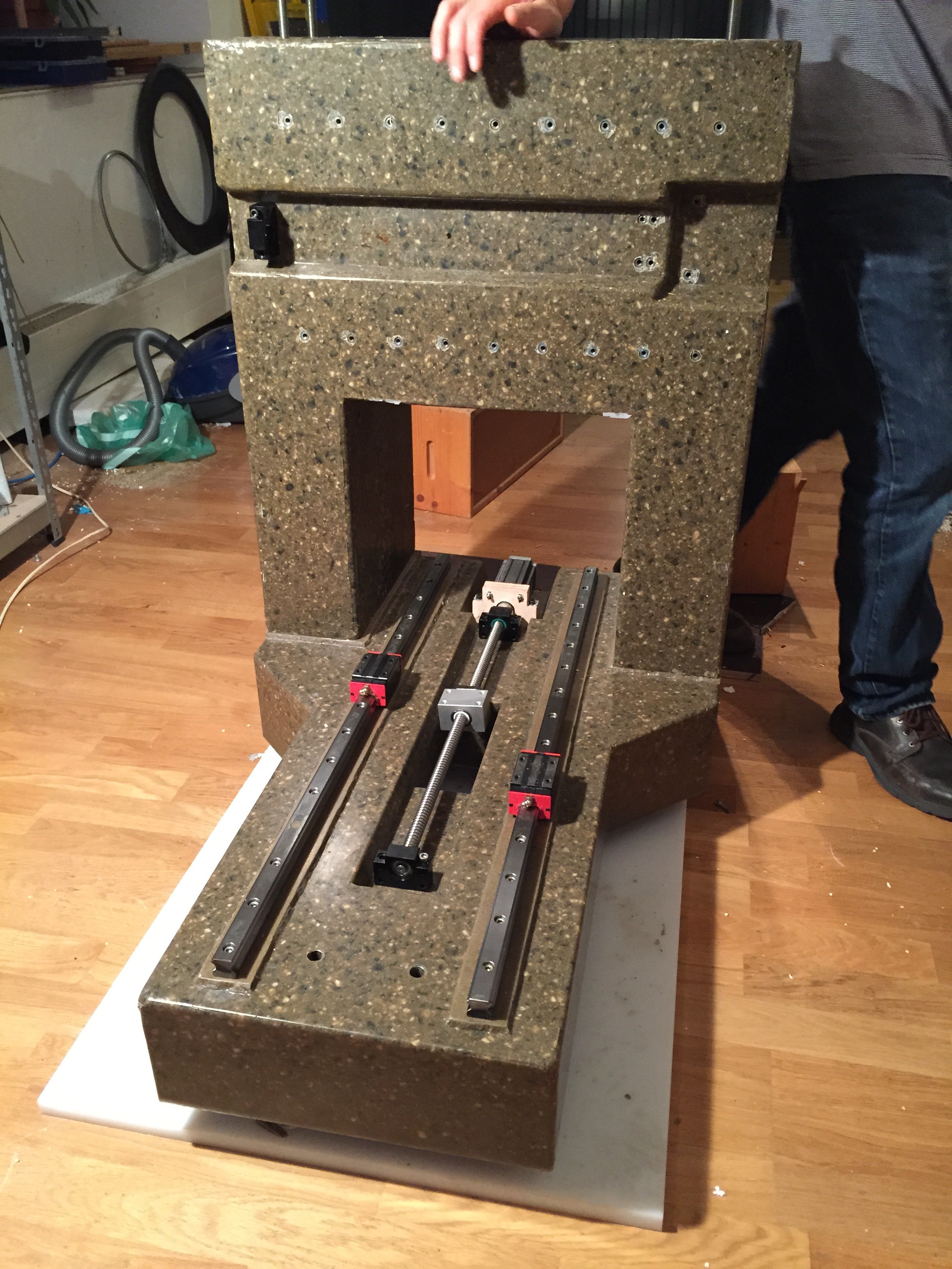
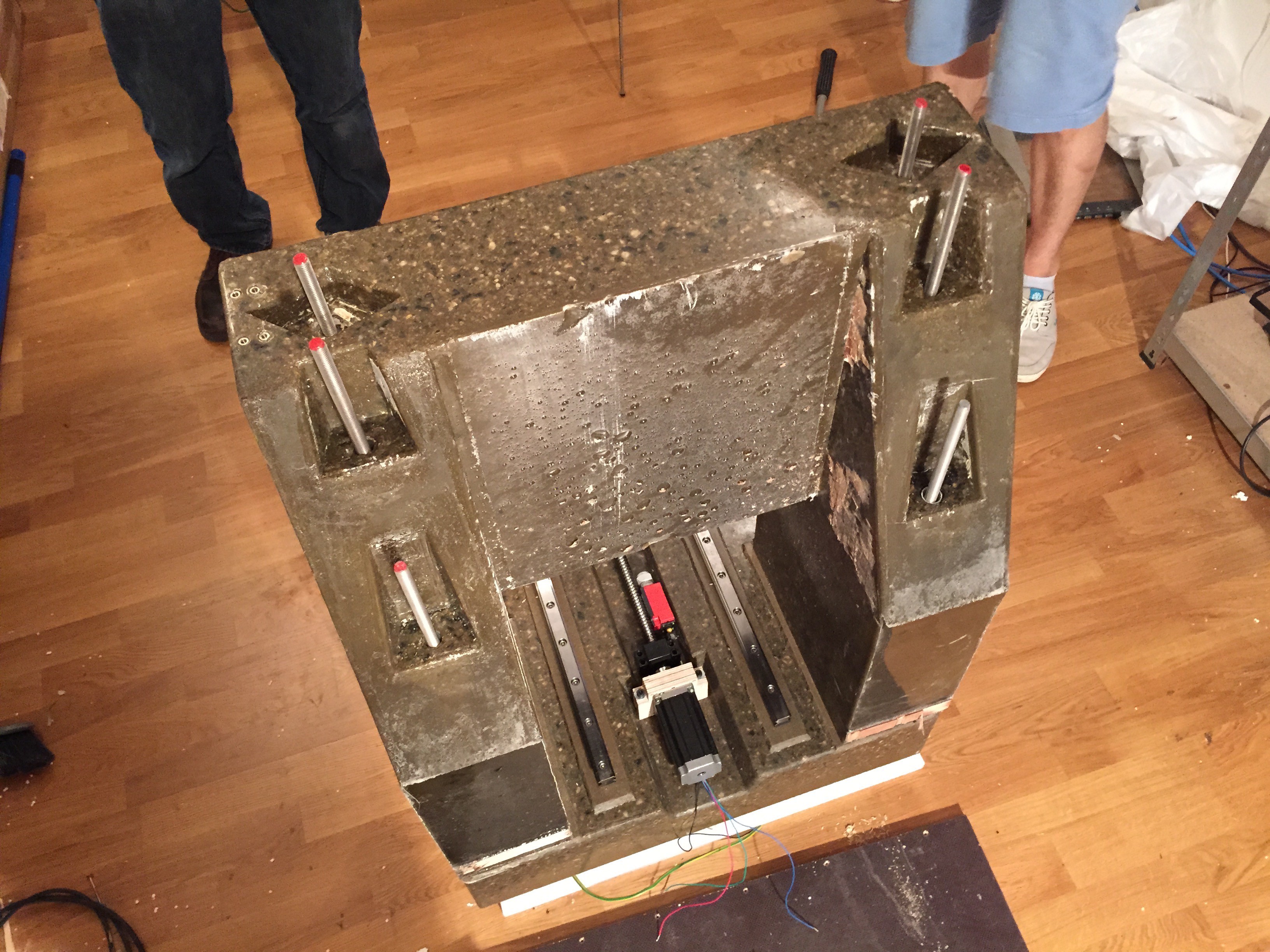
The X 6 Y axis guiding rails where mounted afterwards. They have to be aligned, and orientated to each other, starting with the X axis linear guides.
The rails have to be straightened during the mounting process.
Our epoxy granite surface was not perfect straight and we had no better option to level the surface with tinfoil underneath the linear guides. It may not be perfect, but it worked for us, temporarily. We may catch up on timing the surfaces by face-grinding.
Parallel to the making of the machine, we have made a 3D model with Solidworks. This is a rendering from The machine base:
Next step was to make the Z axis and X plate out of aluminium. At first, we made it out of plywood, than we milled and drilled the aluminium parts. It worked, but in the end of this process, the plywood construction got weaker and we just could replace it with the aluminium in time.
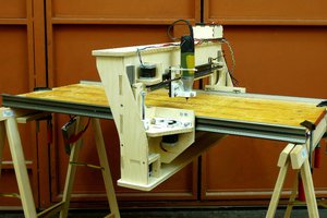
Here are some milling operations with the plywood construction. We gained a lot of milling, machining modeling and G-coding experience during this work. We got a sense about you much strength each part of the machine can handle and where the weak points where. At this time it was the plywood Z construction.
Here are some Photoview render pictures from my 3D Model coming up on grabcad soon:
 3D Meister

 Federico Virdia
 enrico
 morph
morph
 Isaac Zammit
what a pleasure to watch and read this idea you are doing wonderful job I like the idea you can see some more similar ideas here https://bestgearly.com/