Close
0%
0%

PUC: Personal Utility Cyberdeck

PUC is a simple but versatile portable Computer. Running on a Raspberry Pi 3, it has all you need from a simple serial plug, to I2C and SPI.

Public Chat
Similar projects worth following
I decided to finally use my PI 3 B+ in some more permanent, and make it more useful for other projects.

The PUC(Personal Utility Cyberdeck) is exactly that!
A portable Computer for all my(and maybe your?) needs.

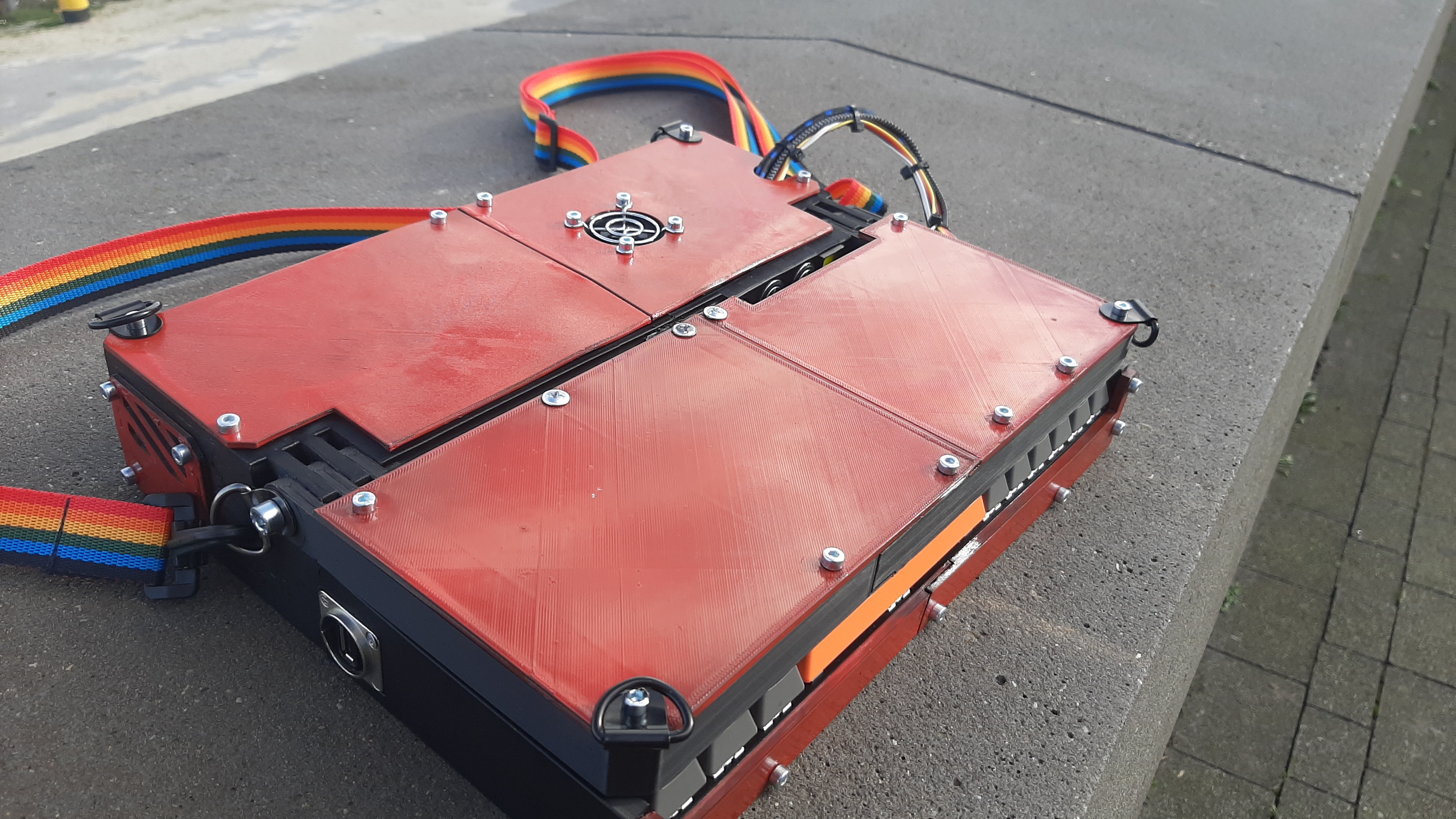
The body is mainly 3d printed. With screw inserts for stability.
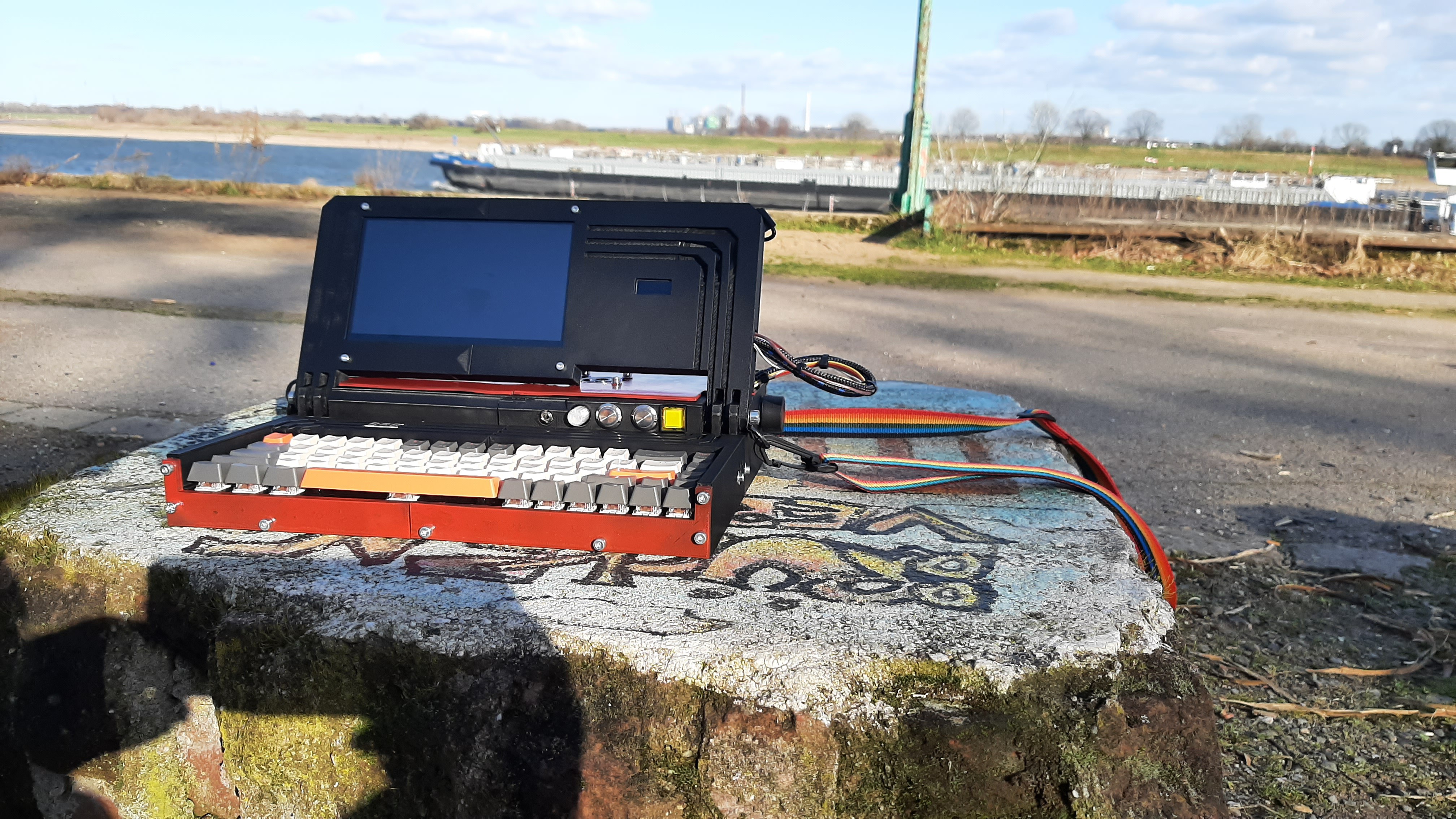
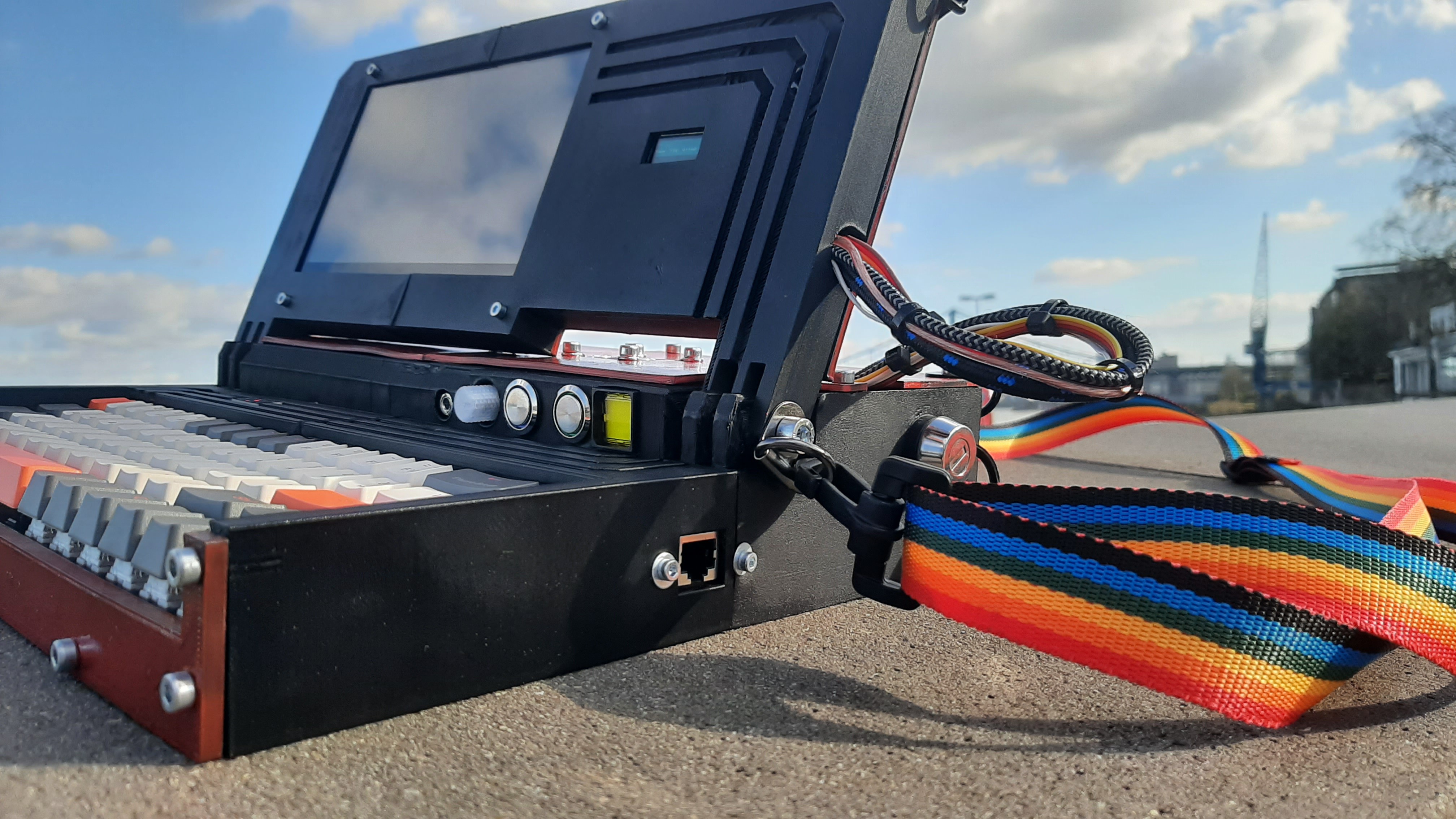
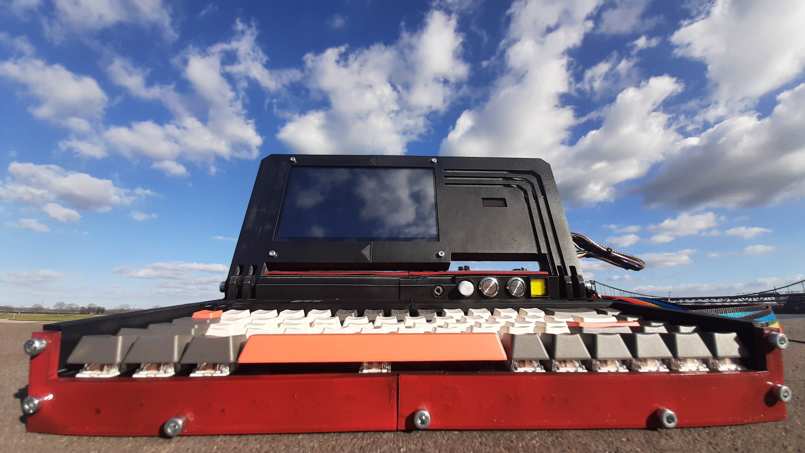
It uses a 7" display and a mechanical keyboard.

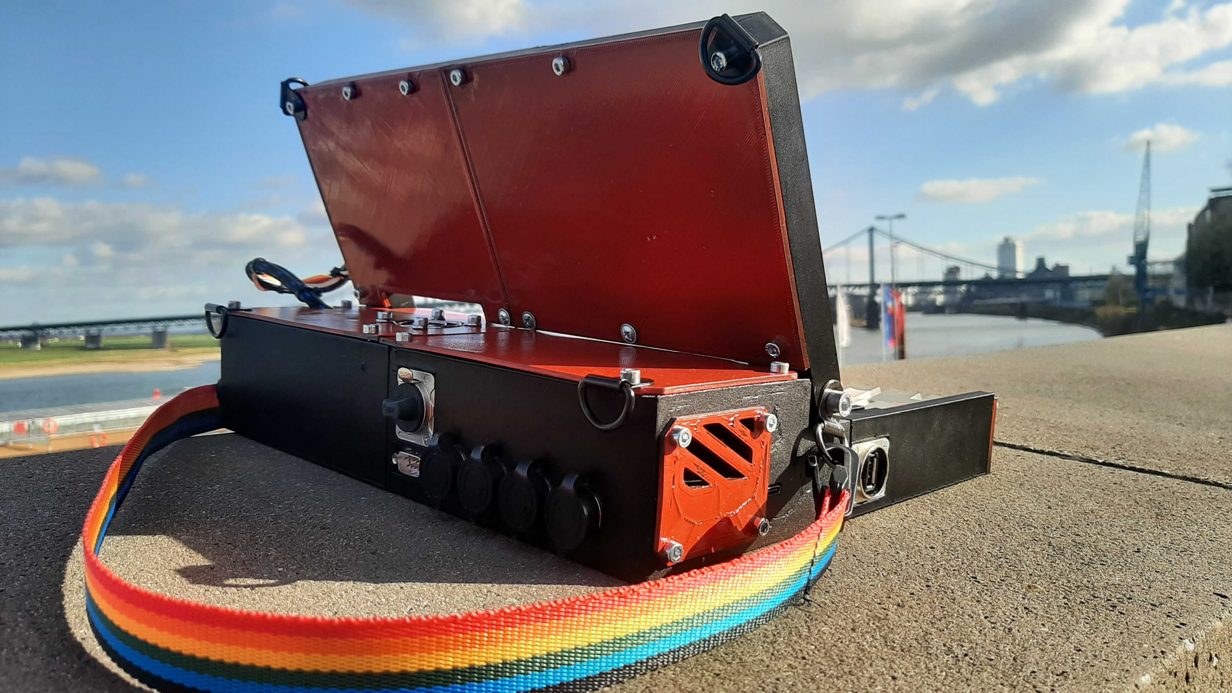
It supports external I2C, SPI and UART devices/expansions, via plugs on the back.
I also added a 6-pin plug for PWM and frequency generator pins on the Pi.
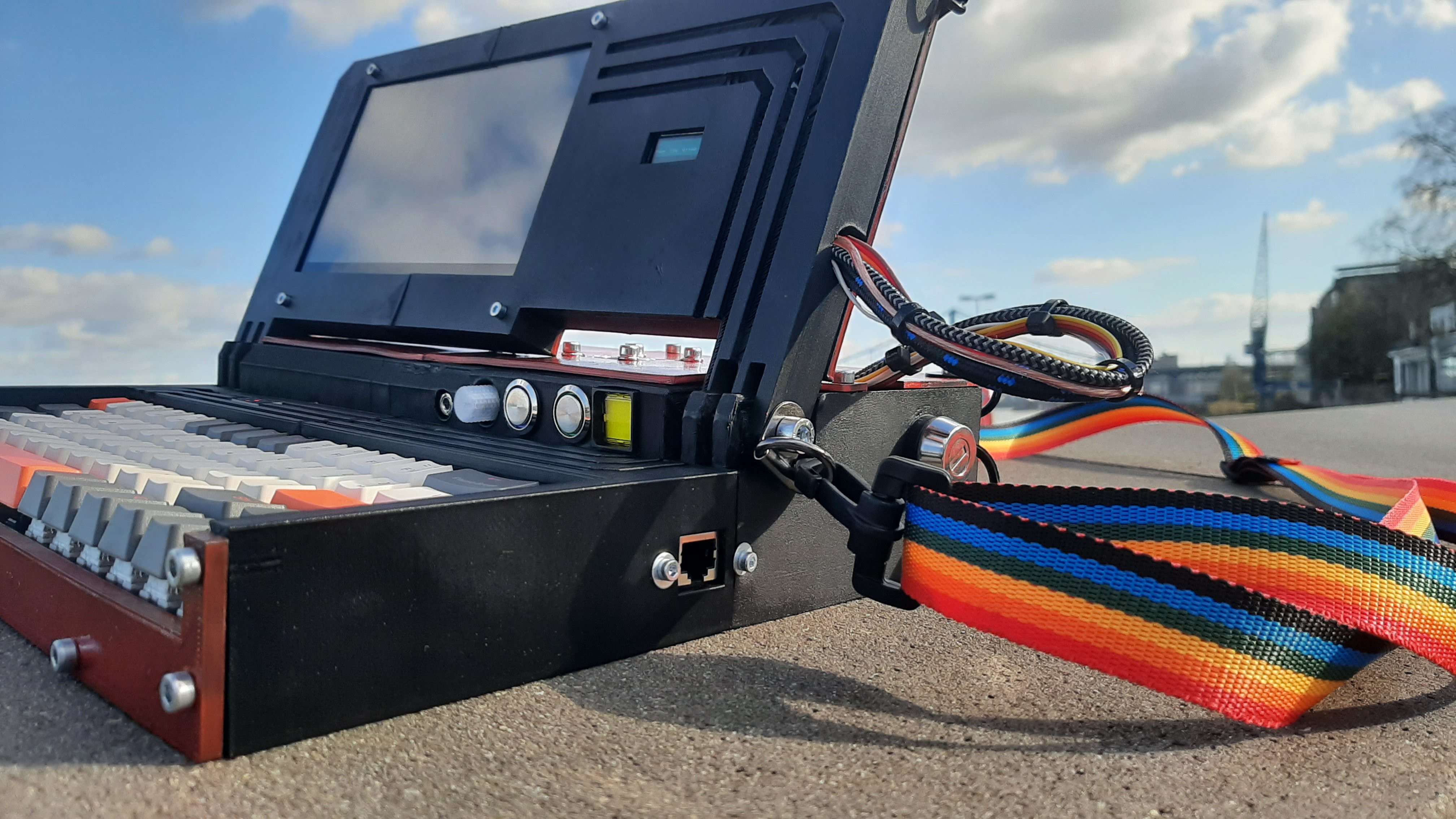
Additionally the PUC has a XLR digital Audio output, a LAN connector, one external USB, headphone jack, Speaker with volume knob and a small stat display on the right of the screen.

The main purpose is a mobile programming station, but it also is a viable laptop, or even a emulation station. It teaches you a lot about programming, 3D printing, and hardware tinkering. My initial budget was 100$ but i overshot to around 170$ excluding 3d printing material cost. Which is not ideal but with the end result I'm glad I continued. The whole weight is around 2.5 Kg, so ideal for mobility.

The Body is 3D printed and designed with Blender. Using screw insets the different parts are screwed together.

Using a 7" Touch Display, makes a mouse or touchpad redundant. And for typing I used a 68 key wireless mechanical keyboard, wireless is obviously not required, it just made the design easier, because of the absence of a cord.

Powered by a 20.000 mAh powerbank, the Pi has a running time of about 7 Hours with the display on. There is a small 128x32 OLED stat screen on the right side of the main screen displaying CPU usage, temperature and RAM usage. Internally hidden is an DS3231 RTC, for real time even with no Internet connection.

I will in the future retro fit it with a SDR.

It supports external I2C, SPI and UART devices/expansions, via plugs on the back:

-I2C is intended for Sensors and Displays, but there is nothing that stops you from making your own expansions, like a GPIO expansion or LED lights, etc.

-SPI is the same, I have no use for now but having it in advance is always best.

-UART can and will be used for talking to an Arduino for example. But it can be used for all serial devices that use 5V. 

The rest of the connectors are the XLR digital stereo audio output and the 6-pin GPIO output for PWM and frequency generator.

I don't have any expansions right now but will soon make some.

The hinge screws have rings attached for an optional, but highly encouraged shoulder strap, making the carying much easier.

The main power is enabled by the side mounted key switch:
Here is a short demontraition video:

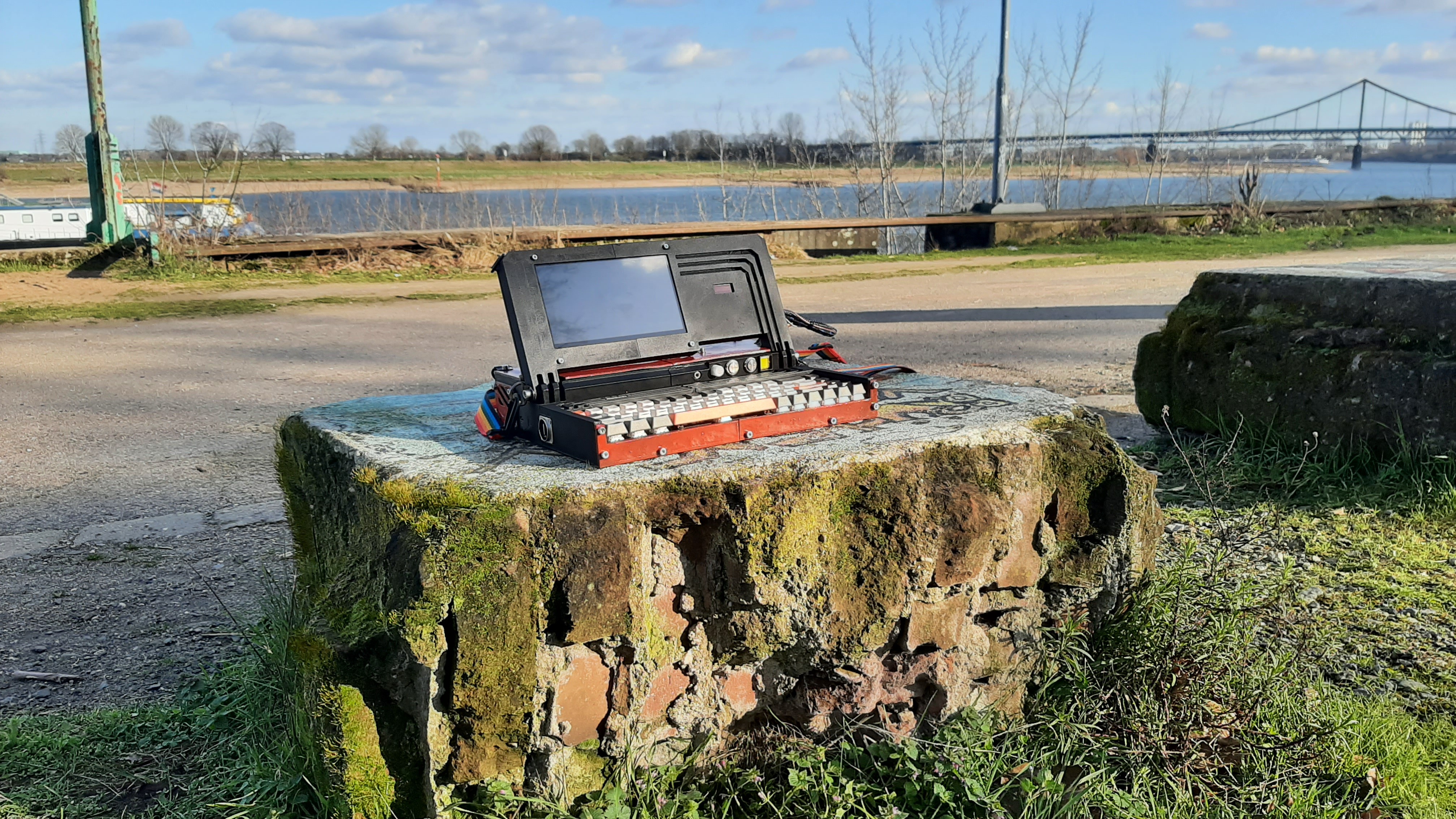
Some more Pics:
PUC_mainbudy_right.stl

Standard Tesselated Geometry - 3.41 MB - 02/26/2023 at 01:37

Download

PUC_mainbody_left.stl

Standard Tesselated Geometry - 3.23 MB - 02/26/2023 at 01:37

Download

PUC_cover_right.stl

Standard Tesselated Geometry - 1.21 MB - 02/26/2023 at 01:37

Download

PUC_front_plate_right.stl

Standard Tesselated Geometry - 380.63 kB - 02/26/2023 at 01:37

Download

PUC_lid_left.stl

Standard Tesselated Geometry - 801.74 kB - 02/26/2023 at 01:37

Download

View all 13 files

View all 29 components

  • 1
    3D Printing

    The files are here and on Thingiverse(https://www.thingiverse.com/thing:5877289), you might need to make some adjustments, if you use other parts than I did, because some of them i had laying around or bought at a local dollar store(mainly the powerbank)

    I recommend printing with PLA 0.24 Layerheight and 15% infill, but it is also okay to use up to 0.32 layer height and 10% Infill for shorter printing time. But be sure to use support.

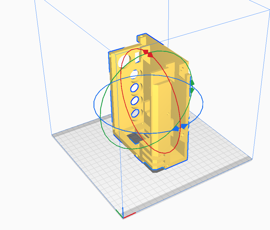
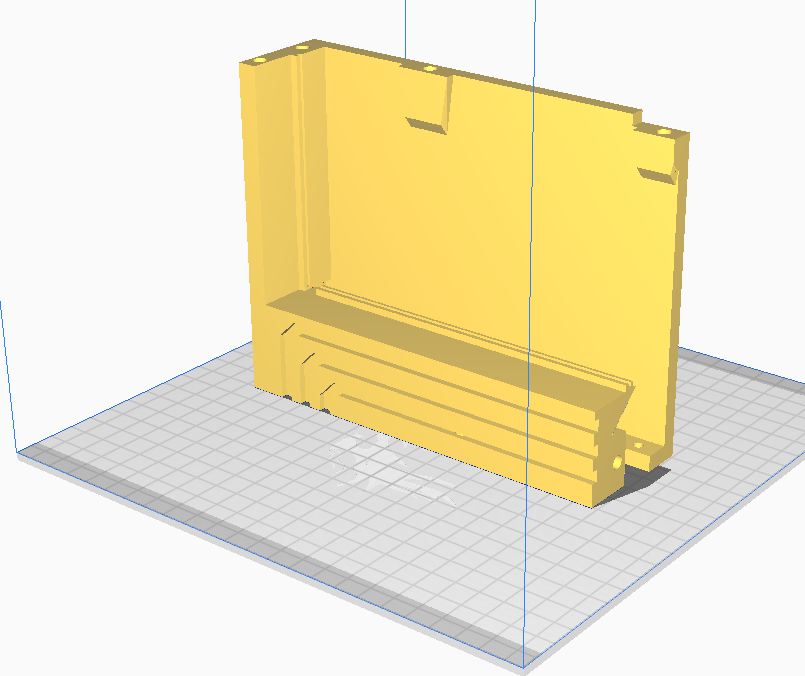
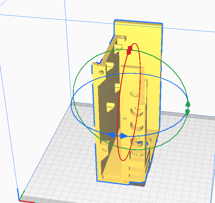
    The files should already be alliend for optimal print orientation. All but the following pictures are the plates that can just lay flat, and these need to be placed like this:

  • 2
    Assembly

    Now pressfit the screw inserts with a soldering iron. The insets and screw holes are always a pair of a 4mm and a 5.6 mm hole. the 5.6 one is for the insets. Screw the main body and front body parts aswell as the screen lid together with M4 16/20mm screws. it should look like this:

  • 3
    Attach the main parts

    I put all the parts I used in the Partlist and for some more specific I added Amazon links for you to either buy or atleast get an idea what the dimensions of the parts are.

    Screw in the screen with M3 20 mm screws and lock nuts in the lid. The same for the Pi, use 4x M3 10mm screw in the four holes in the right main body part. and screw or glue the dissasembled powerbank in the left main body part(BUT BEFORE THAT: solder two wires, one to the 5V and the other to ground on the usb plug of the board). Use hot glue to secure the OLED and Speaker in the right lid part.

    Continue with the USB and LAN ports, the XLR, DSUB, potentiometer of the Amp, Headphone Jack, Power switches, Power light and Keyswitch as seen in the pictures:

    Important: The screw holes for the XLR, USB, LAN and DSUB plug need to be either drilled(DSUB and LAN) or tapped(USB and XLR) for them just drill a smaller than screw hole and drive the screw in, that should be enough to hold it in place.

View all 5 instructions

Enjoy this project?

Share

Discussions

Tim Leslie wrote 11/23/2023 at 16:52 point

Absolutely love this! I’ve loved all of Gibson’s books since Neuromancer first came out. I have an Ender 3 v2. I have a couple of Pi’s.  Mechanical keyboards are the only one’s worthy of use. Excellent design, thanks so much for sharing. I want to take this project on so bad. 

  Are you sure? yes | no

Similar Projects

Does this project spark your interest?

Become a member to follow this project and never miss any updates