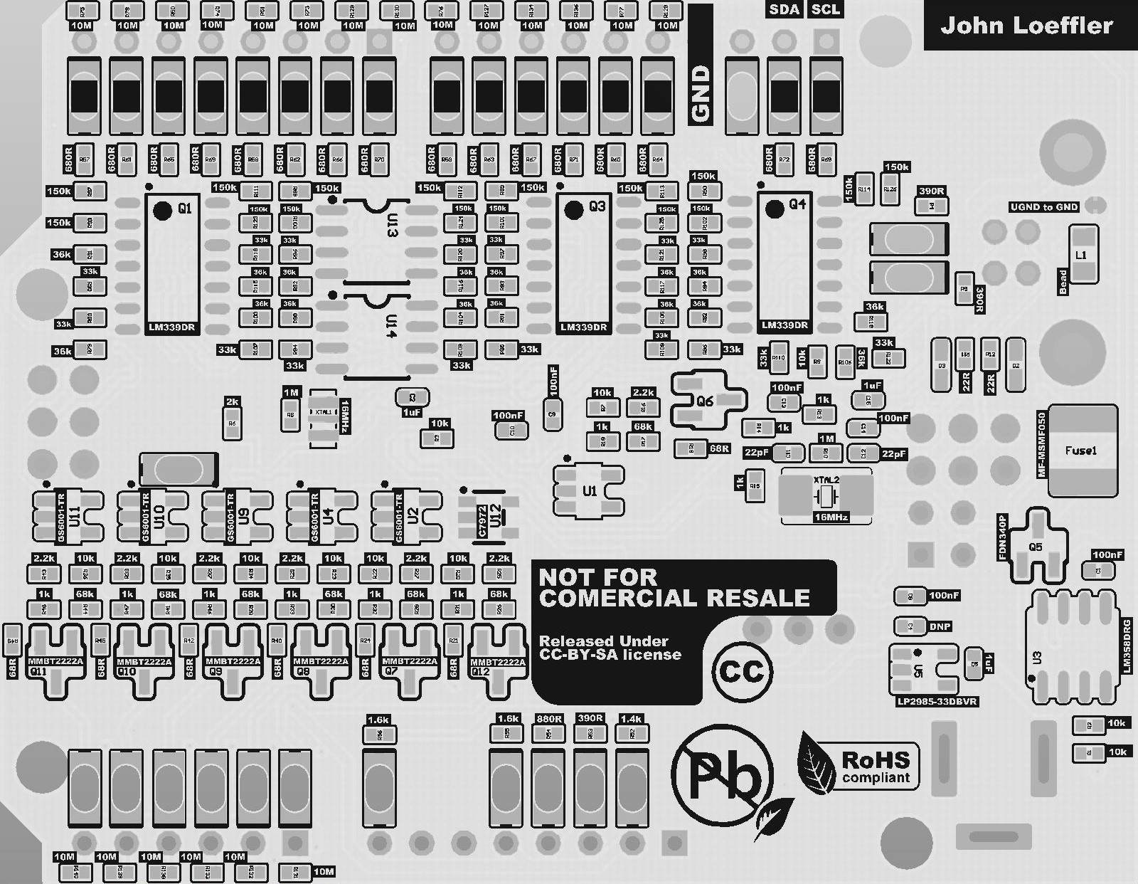
 John Loeffler
 |  |
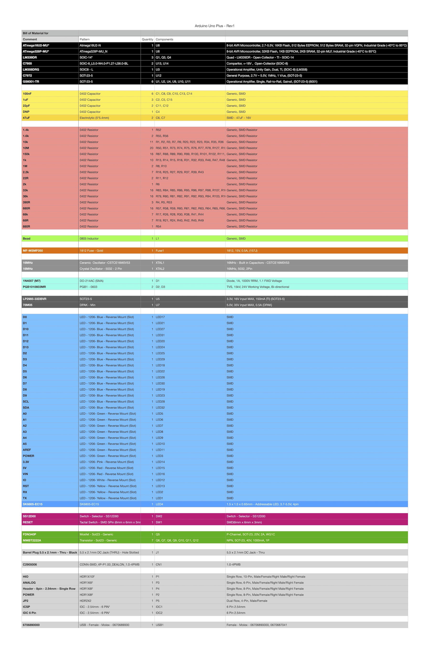
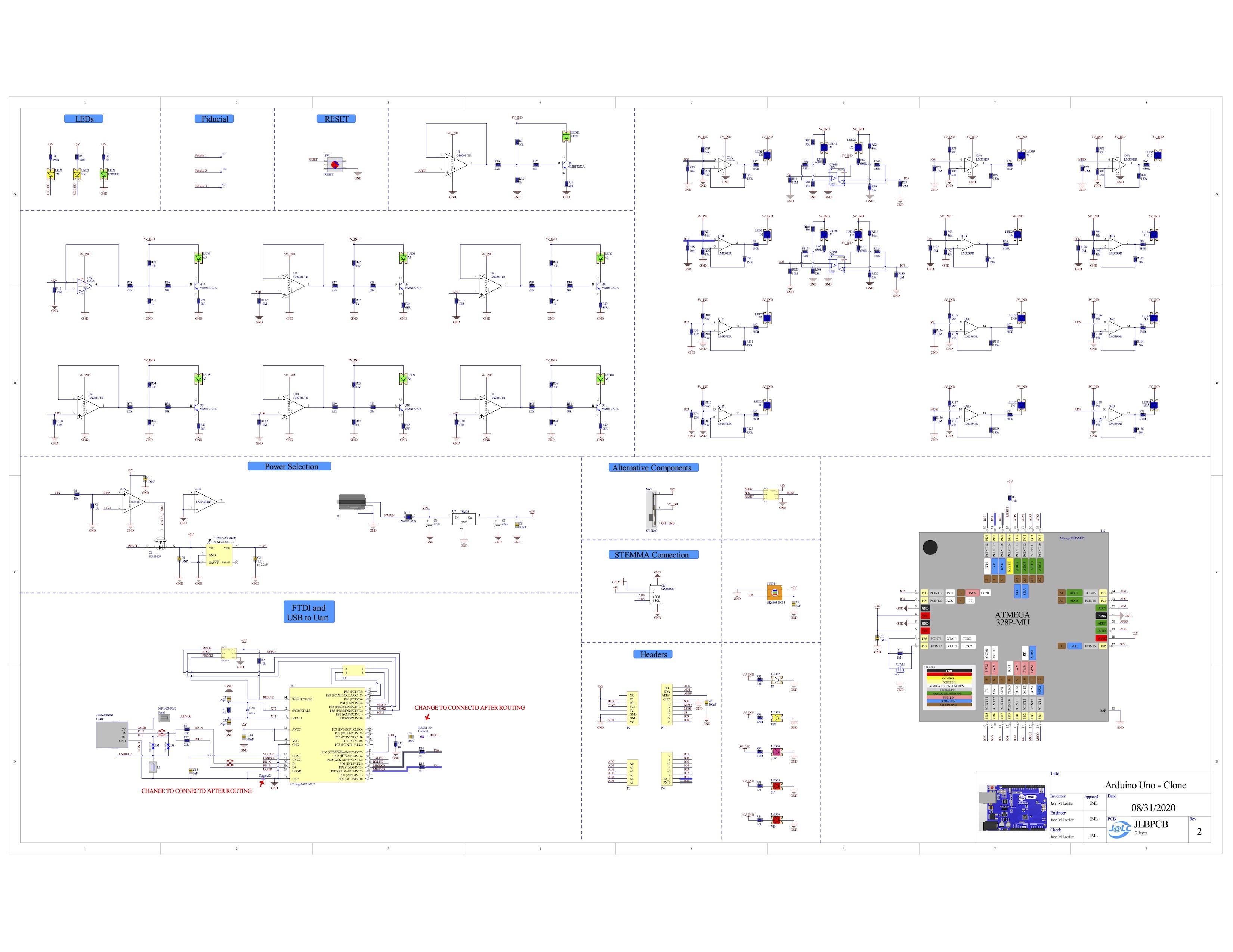
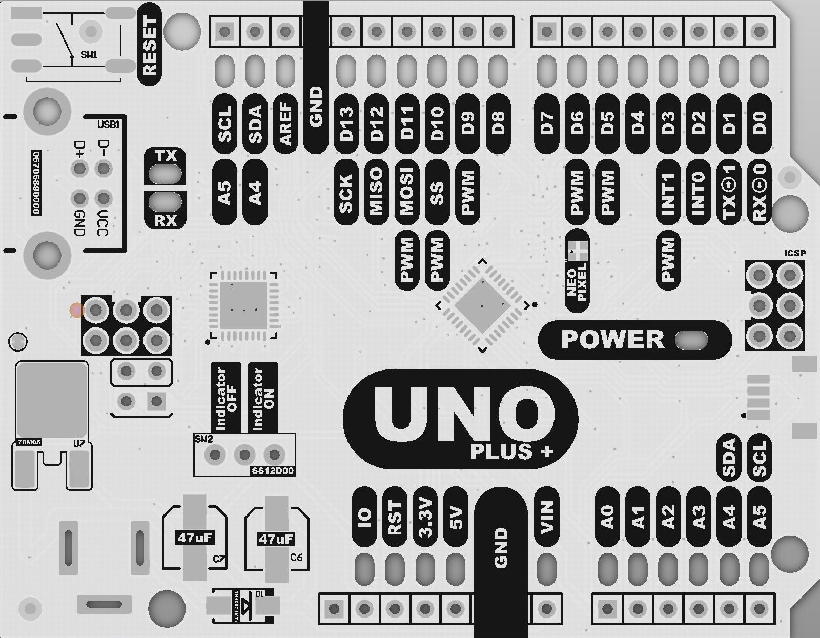
| Analog Pins (A0 - A5) | Digital Pins (D0 - D13) |
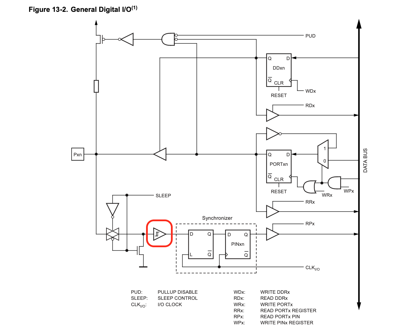
| All Analog Pins Use a Op-amp to "MAP" the 0-5V Voltage to a relitive intensity of the LED | All Digital IO Pins use a comparator with a Schmitt Trigger that will trigger similarly to the Schmitt trigger built into the Atmega 328. |
 |  |
 |  |
 |  |
 Gerber Files | 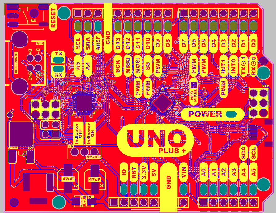 |
 |  |
 |  |


 endevor100
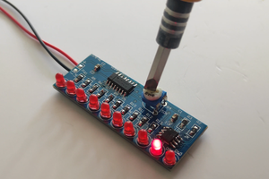
 Grant Stankaitis
 Hulk
Hulk
Thank you for your sharing. I tried to do it myself. I encountered a problem when burning ATmega16u2. Can you share how to burn Arduino Uno firmware?