0%
0%
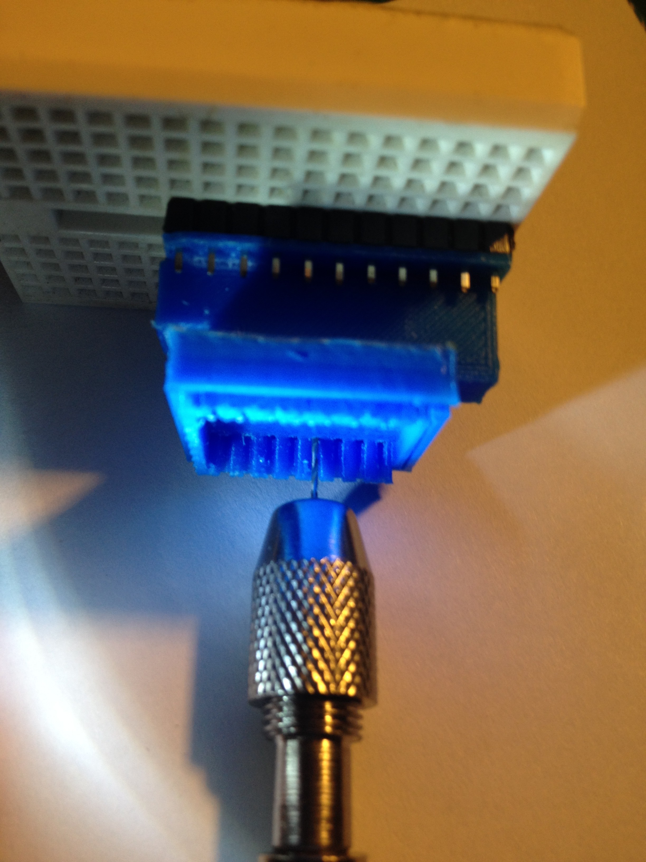
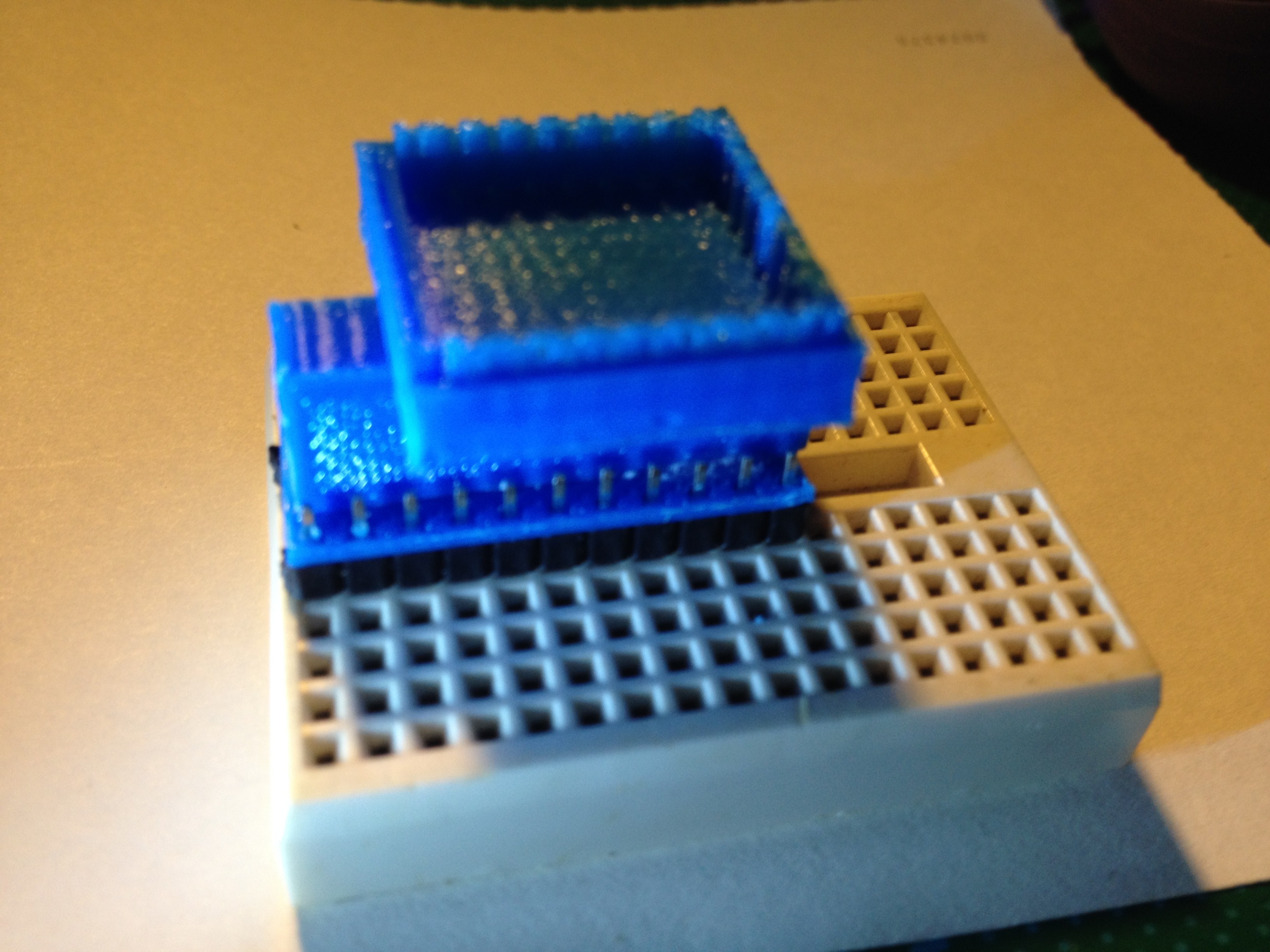
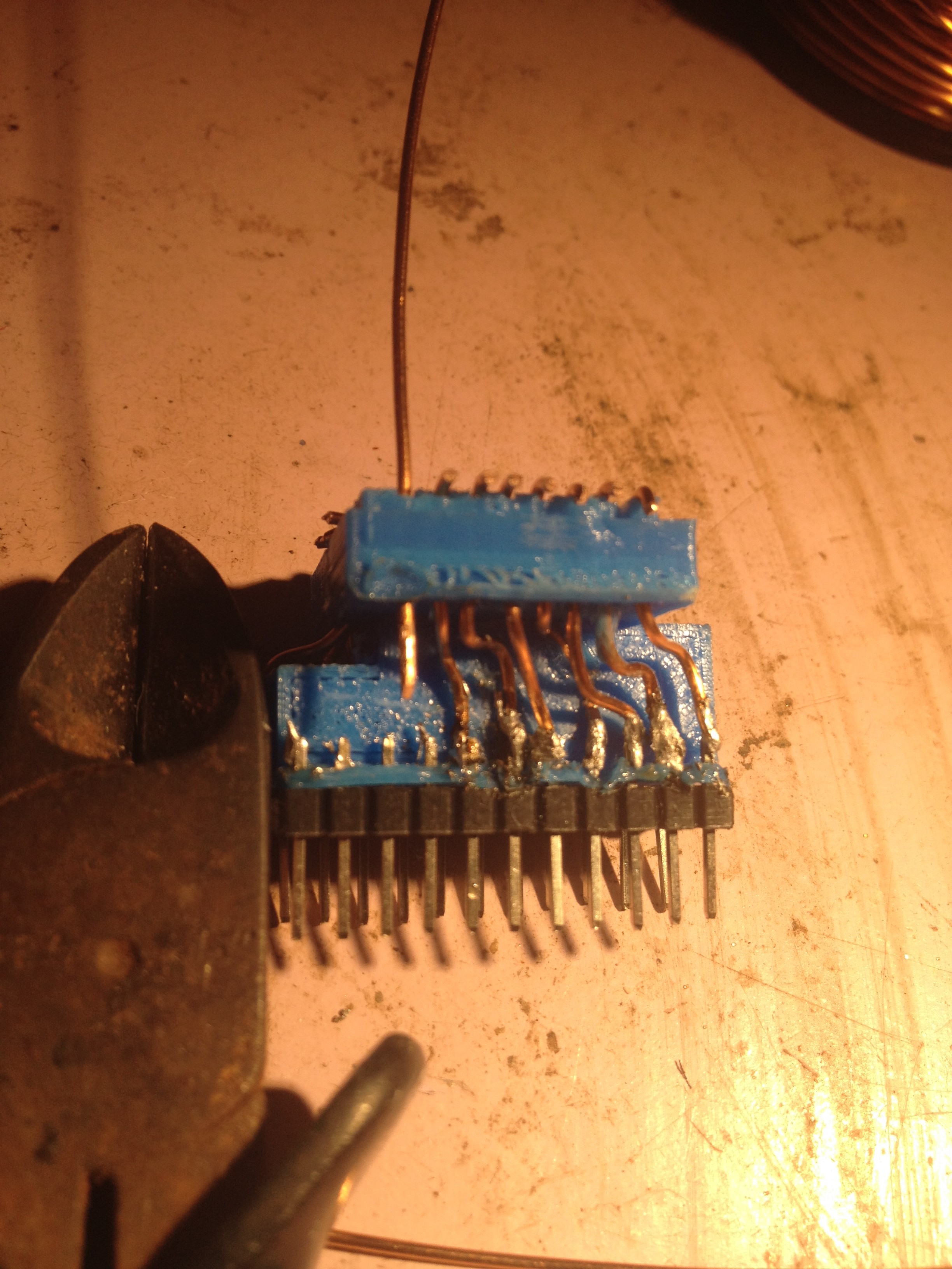
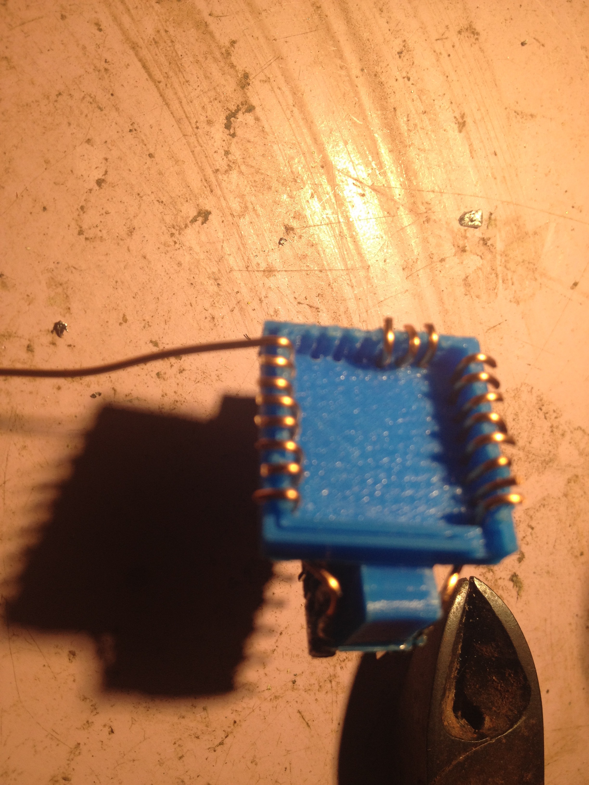
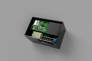
ESP-12 and ESP-14 adapter to DIL
To program or test ESP-12 or ESP-14 before installation, then plug adapter into breadboard and the ESP into adapter. Unplug when done.
 RigTig
Become a Hackaday.io member
Already have an account? Log in.
Just one more thing
To make the experience fit your profile, pick a username and tell us what interests you.
Pick an awesome username
hackaday.io/
Your profile's URL: hackaday.io/username. Max 25 alphanumeric characters.
Pick a few interests
Projects that share your interests
People that share your interests

 Nicolò
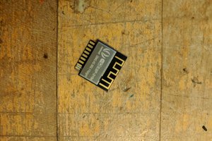
 Sophi Kravitz
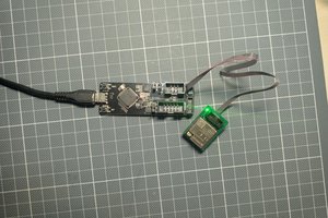
 Christoph Tack
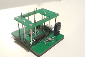
 Vajdera
Great work.
However, if you have to test 100s of ESP modules it will be a true pain to use this method, instead here we got a Wemos board, unmounted the ESP-12F module on it, and added SMD pin-headers instead, that way we just put the ESP-12F for testing, connect it to computer and check if it is working!
Good job though.