 RigTig
-
1Step 1
3 print the three parts, as shown under Files, and glue them together. Ensure all holes are clean enough to get wire through, say by using a 0.7mm drill bit in a hand-held twisting device.
![]()
-
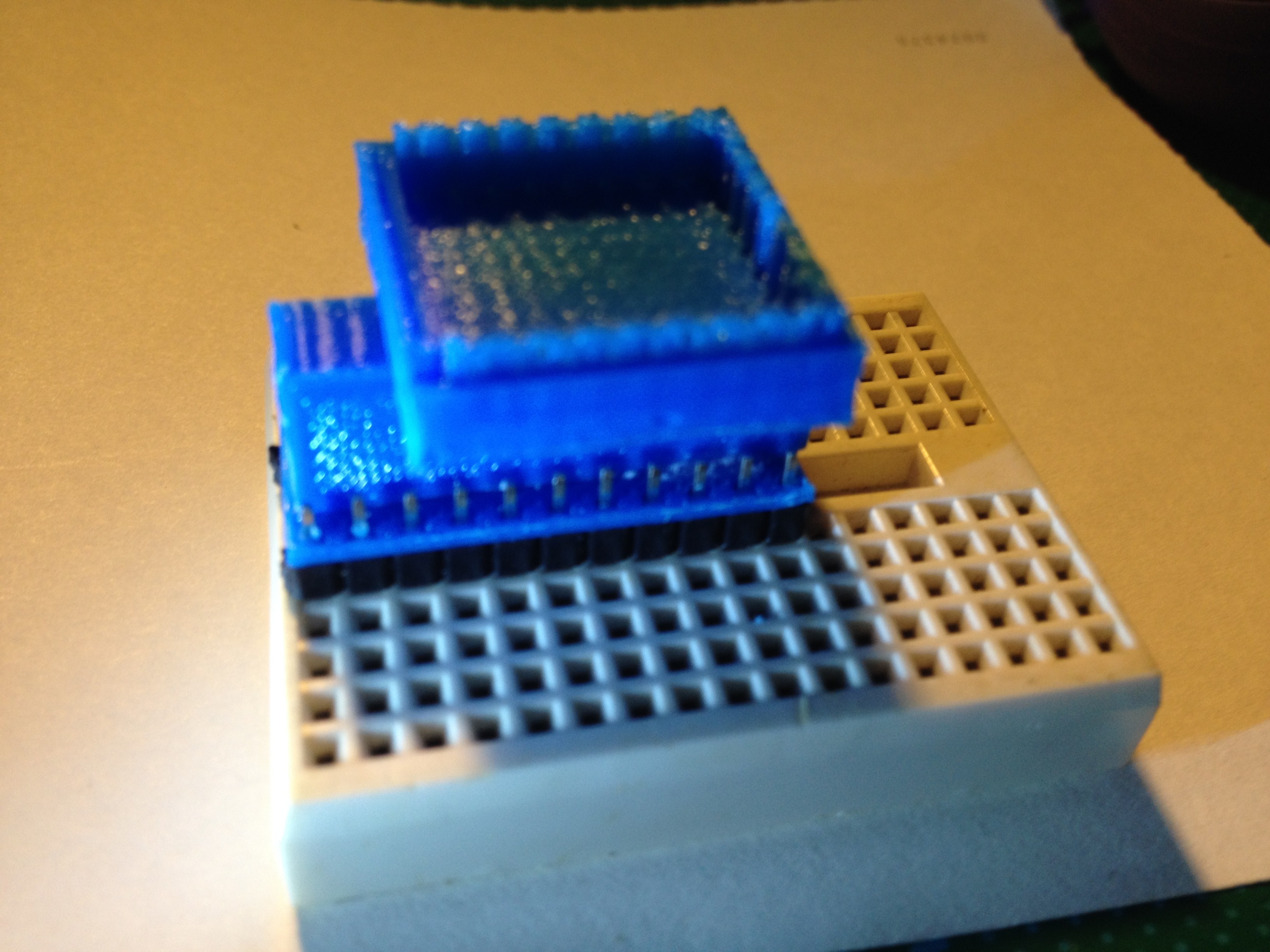
2Step 2
Insert each of the 11-pin header strips into the base plate, with the short ends being exposed against the supporting block in the middle of the adapter. I heated each pin just enough to melt some solder to each of the short ends, ready for the wire to be soldered next. [Hint: Plug the 2 11-pin headers into a test board to support everything better while doing this step and the next.]
![]()
-
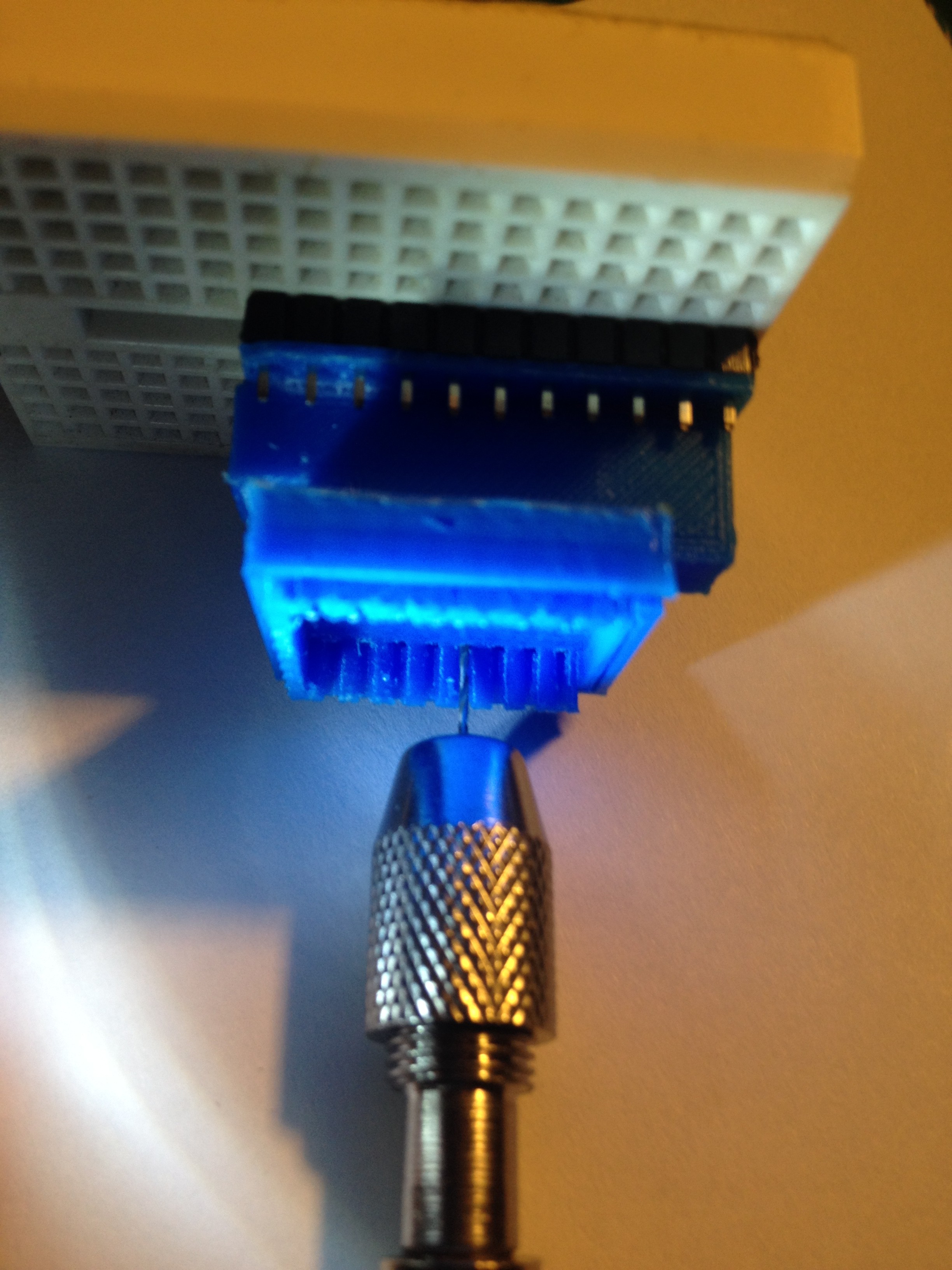
3Step 3
Strip any insulation from the last 2mm of the wire, feed it through the ESP adapter plate and ensure the cleaned end of the wire has some solder sticking to it.
![]()
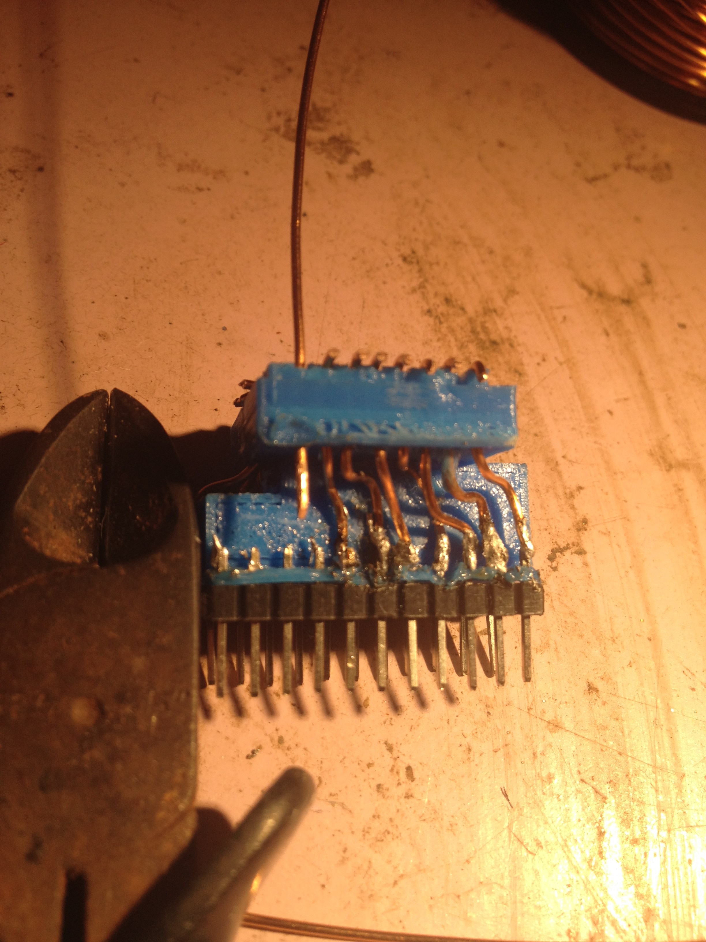
Bend the wire and position it so it lines up with the appropriate pin in the DIL plate, then solder it to its pin. [Hint: thermoplastic melts at a much lower temperature than solder, so keep a heat-sinking grip on the wire so soldering does not melt anything on the ESP plate.] Adjust the wire so it does not touch any adjacent wires. Pull the top end of the wire over the edge of the ESP plate to lock it into place and cut off using side cutters (or similar).
![]()
Repeat this until all 22 wires are in place, and not touching any other. To be sure, I checked all connections were isolated using a multimeter.
-
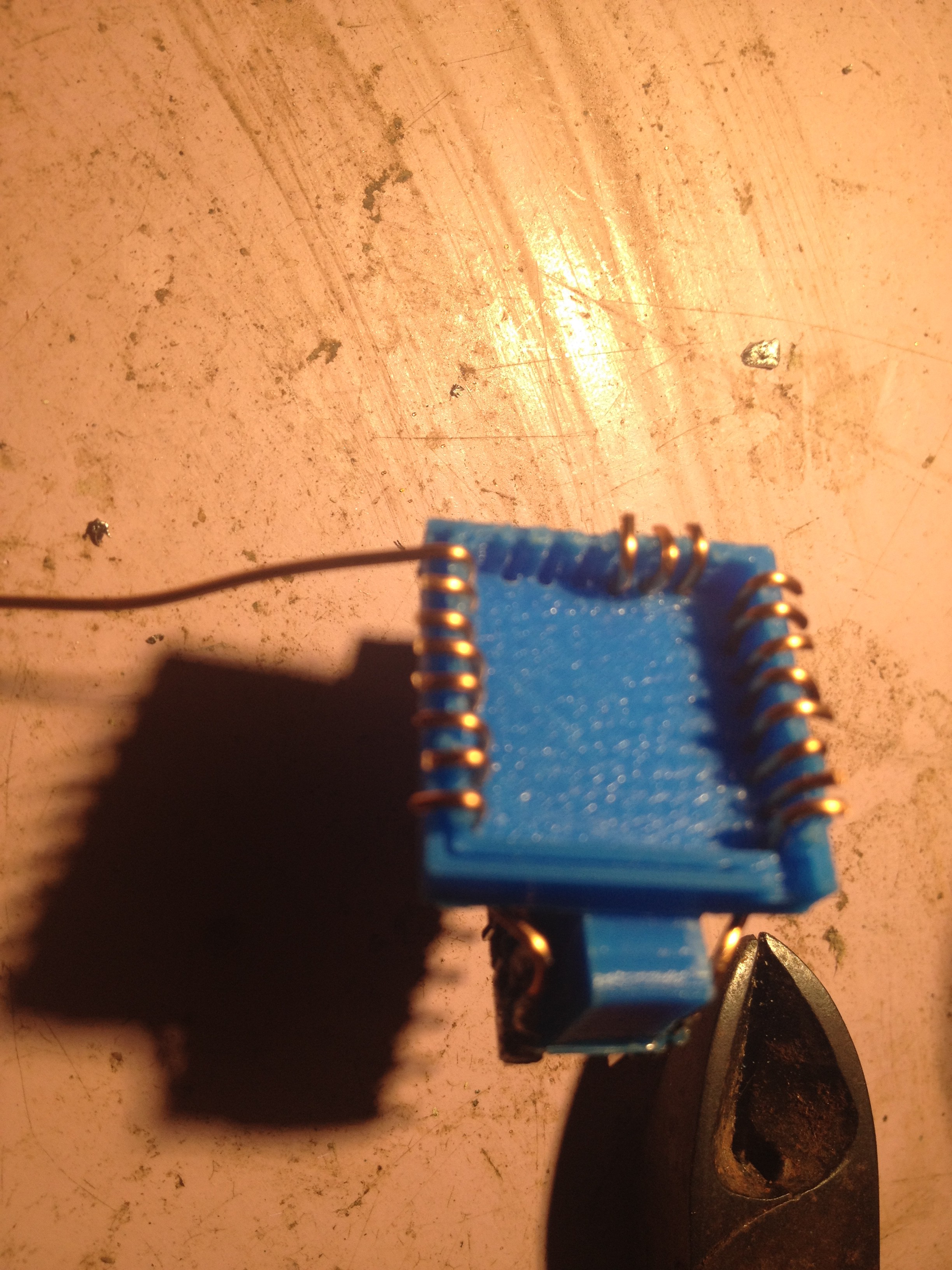
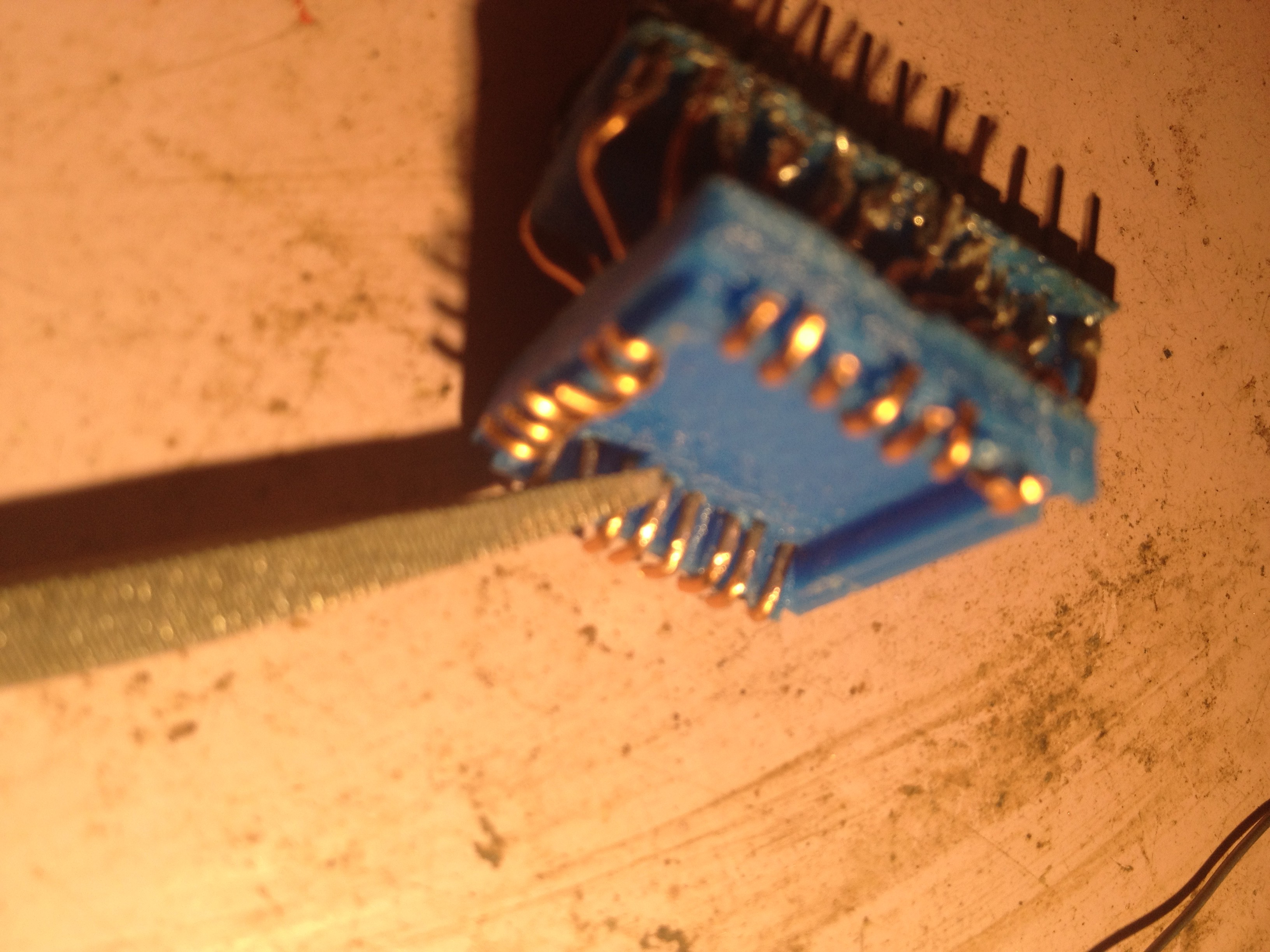
4Step 4
Using a small file, run around the inside of the ESP plate to remove any surface insulation where the ESP module plugs in.
![]()
Press in the ESP module. If you have everything nicely lined up (and you have not melted anything on the ESP plate), you are ready to go. I had to wriggle a few wires so they touched and locked in to the indentations, and squeeze each line of wires so they aligned better, but a check with multimeter confirmed 100% connection.
ESP-12 and ESP-14 adapter to DIL
To program or test ESP-12 or ESP-14 before installation, then plug adapter into breadboard and the ESP into adapter. Unplug when done.
Discussions
Become a Hackaday.io Member
Create an account to leave a comment. Already have an account? Log In.