Dave Collins
-
Greetings Programs!
04/28/2023 at 05:15 • 0 comments
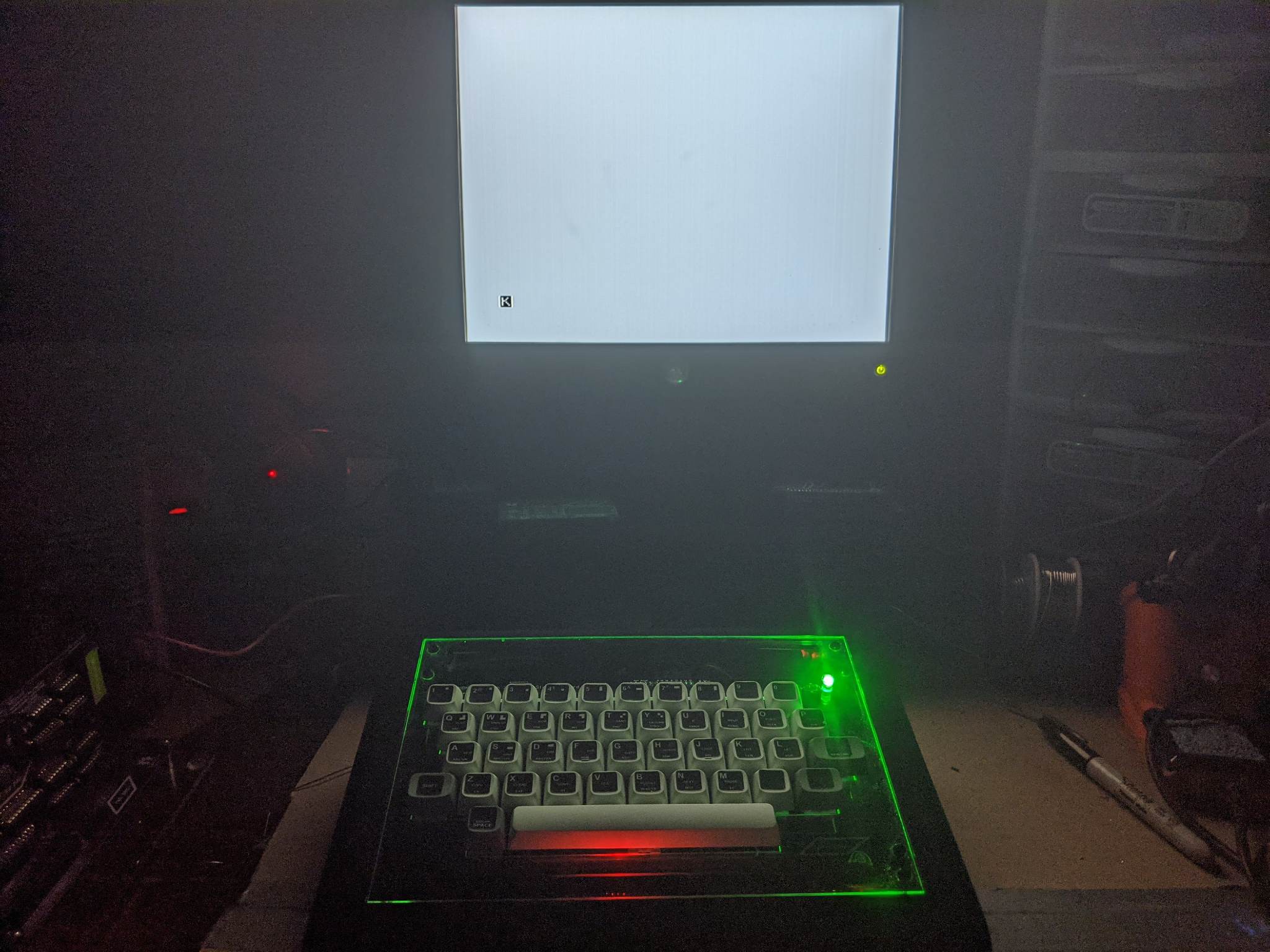
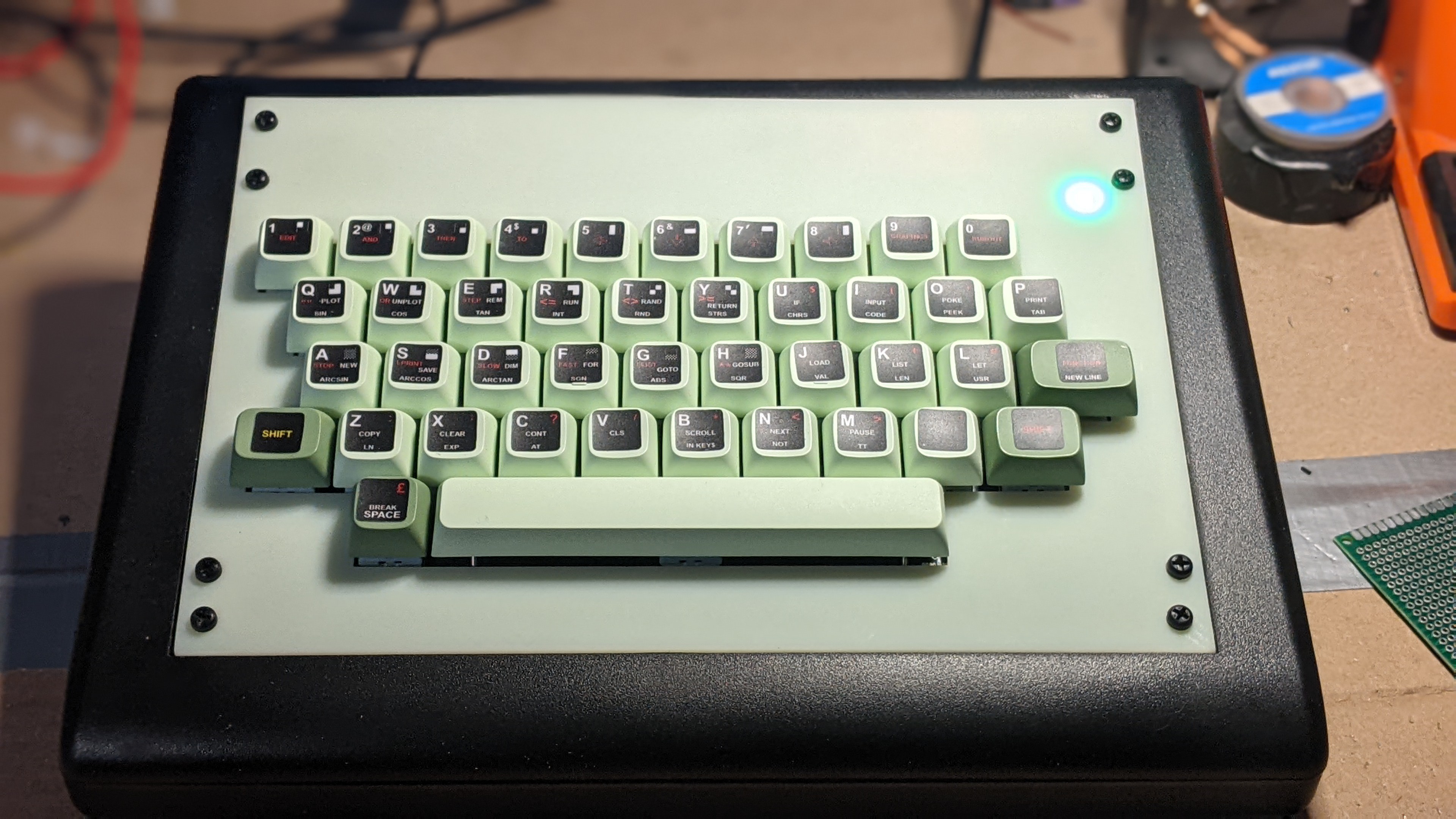
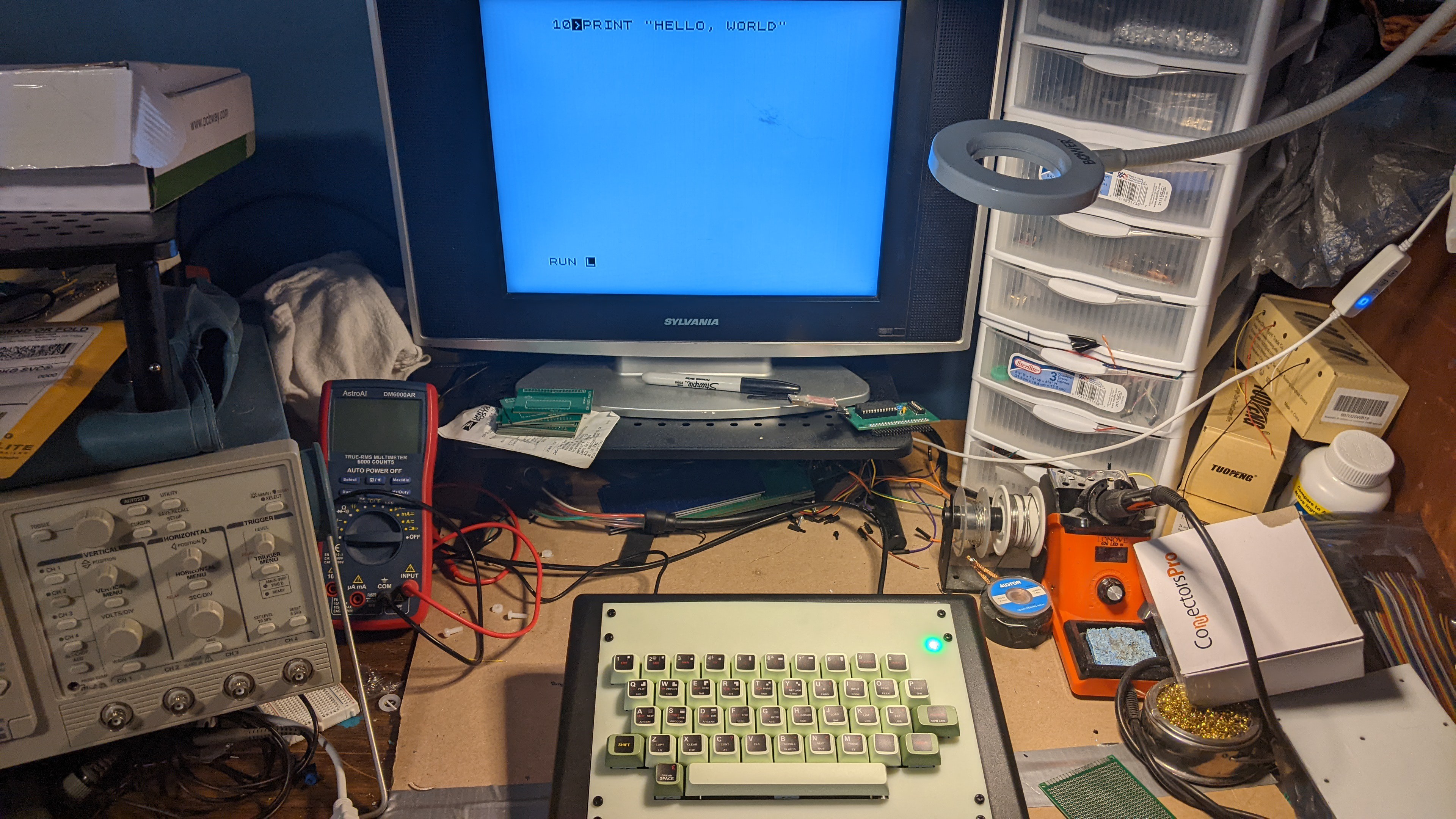
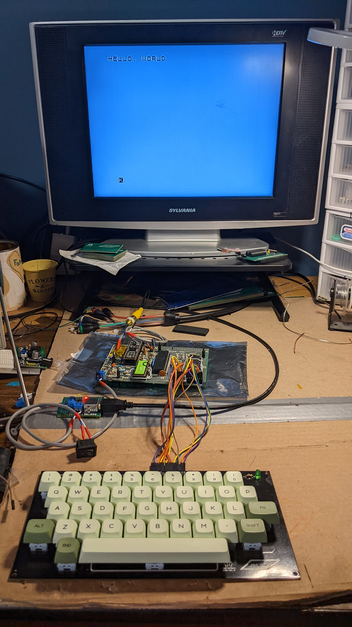
With the test fit out of the way, a few weeks back I finished off the design drawings for the top and back panel for use with a rapid turn laser cut / fabrication service and I think we all agree the results are breathtaking. I went right to work finishing up the inside of the case by adding a new DC-DC converter, a ESP32 for a ZXWESPI and a bit more board work to finish off some of the loose ends that were hanging around from the restoration and now I have a fairly satisfying end result:![]()
I swear to everything that is holy, that is a very nice looking ZX-81 and I am fantastically pleased with it. It looks like something out of everybody's favorite 1980's film about laser bikes. Typing on the thing hearkens back to entering basic programs into my C64 from the ring bound users guide, and I love it.
Just for fun however:
So how did we get here:
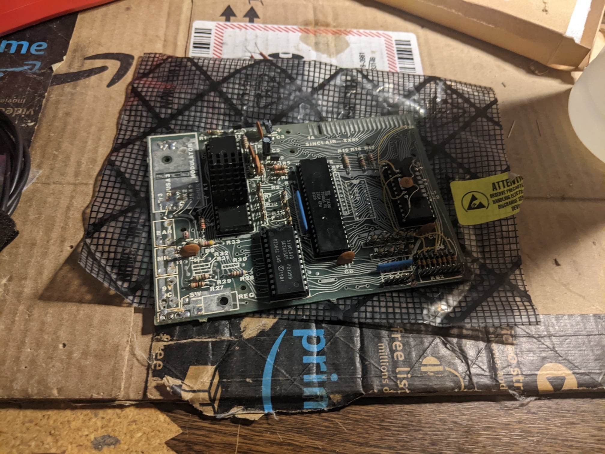
It started out as a simple Christmas gift from a friend from across the pond:
![]()
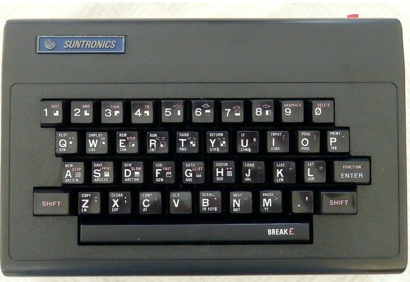
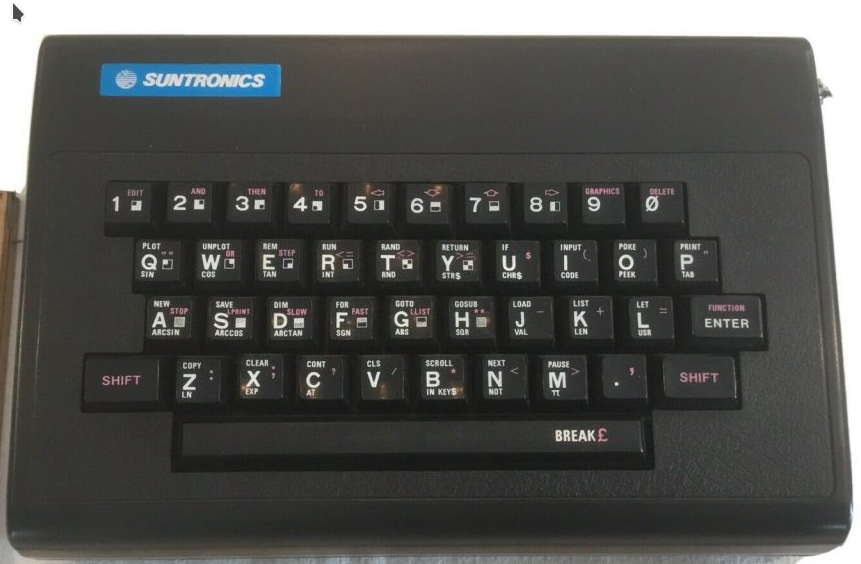
It needed some heavy restoration work and I love that sort of thing, its kind of cathartic In a way. Initially I wanted this to be a fun side project, I was going to hand fabricate the mods using strip board and find or build a replacement case and that would be the end of it. Then i saw iNibleSloth's totally new ZX81 build and I fell in love.You can follow along with the early stages of that restoration in my hackaday "pages" blog. I finally finished the restoration a couple of months later, and started work on the keyboard. I'd hit kind of a snag at this point however, for start's the cases out there were not really what I was looking for. iNimbleSloth's keyboard, in fact most keyboards for the ZX81, lack a space bar, offset shift keys and other nice things that I really wanted. I also wanted a case like the KD-81 from Suntronics:
![]()
The only trouble was, even with the best of google searches; and asking everybody's favorite language model -- you can't really find one of these things (let alone pictures of the inside.) I decided with this kind of fabrication, I was going to need some help and I took a shot and asked my sponsor at PCBWay would they like to participate in making something fantastic, and they agreed!
The fabrication build review:
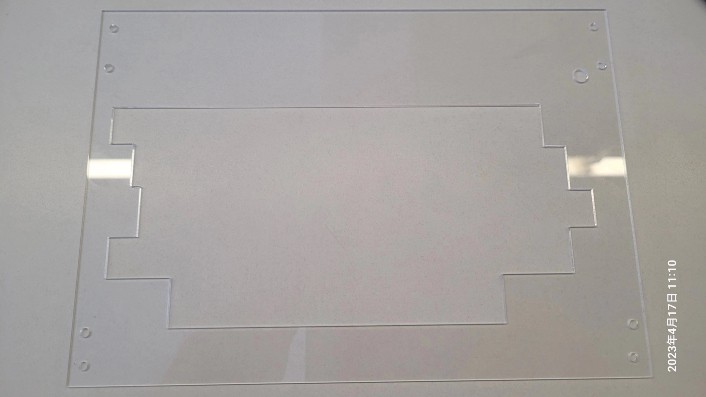
The HBKD-81 is a set of panels and PCB's for the PT-10 industrial sloped console enclosure. They end up looking an awful lot like the inspiration, and I love them. To get all of the fabrication done I used the sponsor of this project PCBWay.com. PCBWay makes fantastic rapid turn PCB's for prototyping and end products alike. Additionally, they do injection molding, sheet metal & acrylic fabrication, and 3d printing. For this project I used PCB Fabrication services for the keyboard, 3D printing services for the test fit for the top panel, and in this part of the project I did acrylic panels which PCBWay cut and drilled and the results are very nice:
![]()
It took roughly 8 days, that worked out to be about a week and a half from sending the design, weekends, a small delay for engineering questions (this is standard, more about that later), and shipping. I was never out of the loop on anything, when they did actually reach out the representative was very kind and asked insightful targeted questions and I was confident it would be handled perfectly, and it was. The only issue was with my design files, There was a hole that was not clearly marked as a hole. The kind people handing the issue on the other end supposed it was a hole and reached out to ask if that was correct. I answered the question and production continued; it was very easy.
The pictures make clear what words can not. The fit is perfect. Nothing was cracked scratched or damaged in shipping. It came packaged along with the other panel and a small PCB I built for testing. Everything was sublimely easy. I was as always, very impressed with the quality, speed and price. Even if PCBWay's costs are a bit higher than the competition having something done right the first time, with no scratches, within tolerances; is worth its weight in gold if you ask me.
Sponsorship is one of the only ways I can keep up this kind of pace. And so for that I am eternally thank full for the care and support PCBWay has shown my projects.
Internal build:
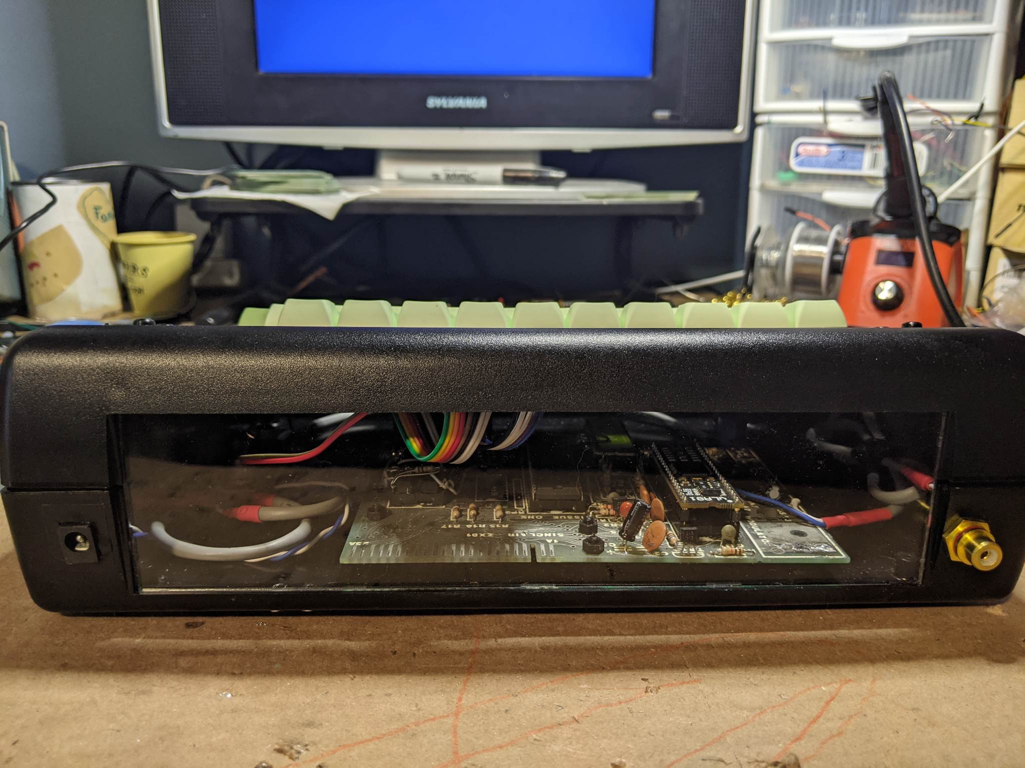
I tried very hard to get the internals right. I really wanted it to come out as clean as possible, and I knew I wasn't going to use the expansion port, so I built a simple back panel that just covers the back:
![]()
![]()
As you can see I went with a standard barrel jack here, If i could change one thing about the build I would have gone with all rounded panel mounts. Cutting the small rectangular openings was slightly nerve-raking! I probably spent the most time trying to make it perfect and it really took a lot of slow, deliberate work. The power port still ended up a bit wonky with a little vinyl bezel sticker to cover up my crimes from the craft knife. The rounded hole for the video port was much simpler as I could simply drill a hole to size.
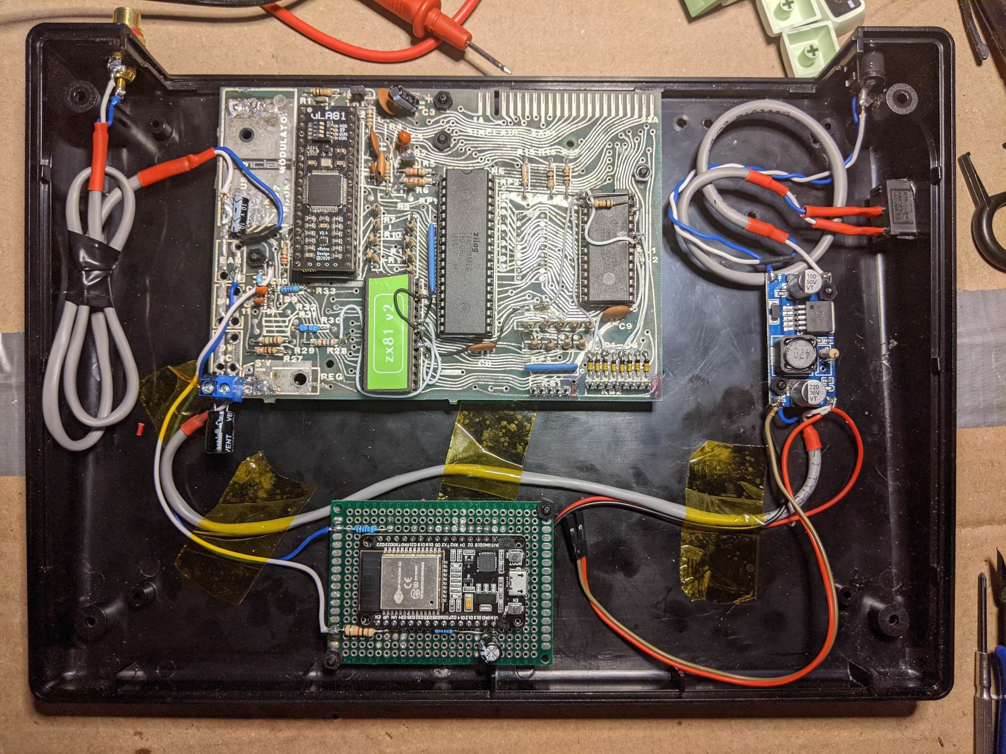
On the inside I point to point wired the power and video sections. The modern ULA replacement outputs a clean 1v PtP 75 ohm signal. To resolve the DC offset I installed a simple electrolytic cap and wired the video line directly. I built a small proto-board up, with the zxwespi-iot-mi version, and finally installed a 3A bog standard DC-DC Buck converter for cool, clean power. The only issue I ran into here was I needed to install an extra bypass cap at the output of the module to bring the ripple down even further to eliminate some high frequency interference in the video signal.
![]()
The video and tape port patches for the ZXWESPI were made directly to the top of the board. This was made simple by the fact that all of the ports had been salvaged by a previous owner. I did have to tone out an alternate location for the video patch, but as there are multiple via locations on the top which are gigantic by 2023 standards this was no problem at all. Here's the best bit. due to the positioning of the ESP-WOOM module at the front of the case, when the module accesses the network or loads a file it looks like this:
Complications, solutions, and conclusion (how can I get one):I did at the very end run into some issues with some of the sockets needing a re-flow from the backside. As I was working on principle photography for this very write-up I ran into RAM type Video issues. looking at the back of the board I discovered more cracked traces under the ram chip. The biggest issue is the board's finishing is de-laminating on the bottom side, and is aggressively salt water corroded on the top. This lends itself to its own unique set of problems but as I am writing this I have been running hi-res invaders demo loop and it has yet to crash, or have any issues.
This about wraps up this project. I am very pleased with the results but the more I prod at this old board the more I grow concerned I may damage something. And so, I think it best to move on and enjoy it for what it is :). I will definitely be re-visiting the PT-10. I still want to build a off the shelf retro terminal (ESP32 or Pi-PICO based. I haven't put much thought into what it might be. For now I will be re-focusing on the next generation of HB6809 upgrades and looking to that.
As far as getting your hands on your very own HBKD-81 you can certainly try to build your own. Over the next few days I will be releasing all of the source material I used. I don't think I will be making them for re-sale at this point. The main reason being, even though its a low cost build, its still firefly spendy. I'd say probably in for about $150-$200 building one of your own. I don't like the idea of asking over $100 for something I designed with no engineering experience. Additionally, I probably over spent on some of the parts to get them quickly so that I could meet personally set deadlines for projects. Obviously there's no such thing as no, for crazy money, you are always welcome to reach out and we can discuss it but this was a lot of work, and I work another full time job. I don't know if I have the time or energy to build another one, and still work on the other things that make me happy. I do however have a few extra keyboard PCB's i don't need extras of. If anybody who's serious wants one I'll throw it in a USPS box for just the cost of shipping.
Thanks for sticking around to the end on this one, its been an amazing trip start to finish. Please leave a note or a comment if you have any questions. I'll post an update when the project files are all uploaded, I really hope others can have the joy of completing one of these things building your own keyboard case is a huge thrill.
-
Pannels 3d Prints to test for fit
03/28/2023 at 17:01 • 0 comments![]()
Looks like the 3d Test panels fit:
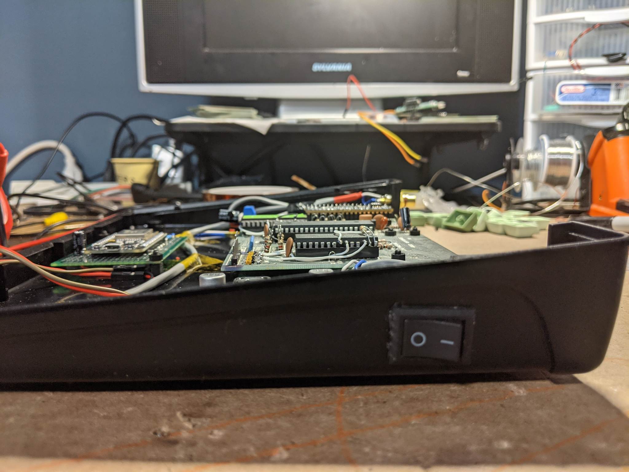
So after waiting about 2 weeks to get the panels, they came and we have basically a working case! I won't bore you with the back panel hack job I did getting the switch and the video port mounted, it's basically just drilled holes in the back of the case the switch, power port and the video port fit into. I had to do a little grinding on the round holes i drilled for the power switch, but if somebody else is doing this -- my recommendation is to go with a round panel mount; this way you don't have to cut a rectangular hole. On second inspection; it might also be better to build the USB port this way and solder all of the passives point to point. This is just a large 100uF capacitor which acts as a bypass; and to smooth things out a bit coming off the USB block. I will most likely have a new panel cut when I do the finished one's so that I can do exactly this... as I am not super happy with the way the switch looks and I think for sure the power board is overkill (just something I hacked together on a piece of strip board).PCBWay Print Review:
The 3d Prints from PCB way came in about 2 weeks. This is due to the 3-4 day build time, plus the shipping to my house took a little longer with fed-ex than it usually takes with DHL. But DHL has gotten ridiculous in terms of price over the last month (at least to my area), so our marketing contact recommended FedEx this time, which was fast enough, and considerably more fair in charms of pricingThe print for the upper panel was done using a more rigid resin than the inside panel In the end I didn't even end up using the panel insert for the interior because the stand offs made the board sit to high in the enclosure. Additionally some of my measurements were WAY off; and so I ended up just going with that upper panel. The power LED from the keyboard was a bit large, and so I ended up just drilling out the hole. I will fix this in the STL I am uploading today but as you can see the panel fits in the top enclosure like a glove.
The prints provided were almost square to the drawing. I expected a little sagging but even this was minimal. All of the screw holes lined up perfectly, and I did not need to do much in the way of anything to get the keyboard to fit in the space it is supposed to sit. I know very little about 3d Printing but for my application they just worked, so I can say that for that I was very pleased. The rigidity of the 2mm panel was not the same as a metal panel but it does not feel like it is going to tear or shatter; if you have to go with 3d prints instead of a laser cut insert they are functional but they do wobble ever so slightly.
Over all I was very pleased with the actual quality of what I got. I would recommend this service for any large format 3d printing you would need. the prints that I got were very accurate to the drawing, and fit for my application. I don't think you can ask for more than that however, PCBWay delivers on that and so much more. They will do several finishing steps as well, such as painting the parts in the color of your choice, if you are not confident with a spray can. I would definitely recommend this as a 3d printing service, especially for large format parts.
What's next:
![]()
At this point I am happy with the build for the ZX81. The computer functions, runs basic and the keyboard is more than I could have hoped for. I'll most likely go for some laser cut panels next to really polish out the case, and I will be fitting a ZXWESPI for loading applications via WIFI. I think I will most likely do the VGA version, but I still want to think on it a bit. I will be putting the terminal build on hold for a bit as I re-consider my 6809 build next. I am going to adapt the ASSIST09 Serial Machine language monitor to work with the 16550 UART; a project I have been putting off for some time -- and I think a face lift is in order for the motherboard -- so I will be doing a rev2-mini PCB that will have minimized address decode ( a custom chip i am calling 'Bella') as well as try to bring the cost down even further. I would really like to make a PCB that fits exactly inside the terminal case when its finished.As far as build files for the keyboard I'll be posting the STL's for the upper panel If somebody is trying to build one. I know it fits in the case and so I am comfortable releasing it. I used a set of stand offs and screws from this kit on amazon.
-
Prototyping... 60% of the time, it works every time!
03/13/2023 at 04:56 • 0 comments![]()
Project update:
What a RIDE this week has been! Every once and a while you put a thing down into the EDA, shoot it off to production buy all the parts everything comes and the thing comes out working, EXACTLY like you thought it would!I can't even begin to hide my excitement! This week I got to see a lot of great feed back from the community on the ZX81 Keyboard build. Some of you even started to clone the repository (about 7 of you, lol), and that's real exiting to think about as I only really make this stuff to share it with you. I made the decision to pull the trigger early and share the gerbers with the ZX81 Community on Facebook, and pretty much whoever has access to GitHub. And so, I needed to do some finishing touches to the repository to really round out the production files for the keyboard PCB. This meant the task of creating a BOM spreadsheet for the shared projects website, as well as for hack a day and to include on GitHub. I spent the last few days doing that as well as applying these very cool stickers from 4keyboard.com (not sponsored, just a fan):
![]()
Board review, black solder mask:I am really pleased with how those turned out. First time with the black solder mask, That looks really great! I was blown away by the quality of the Finnish, sometimes the lower cost non-matte black solder mask can look washed out, but this is beyond sublime. The mask is so dark you actually have a hard time seeing the traces below; I really like that effect for a HID device it makes it look much less like a PCB and more like a thing that is meant to be touched. PCBWay did a fantastic job with the boards, and I am continued to be blown away by the level of support I have gotten from project sponsorship. Especially on something as expensive as a keyboard! If the pace of these projects is effected by one thing it is prototyping cost, and so to have a partner like PCBWay assist with that is beyond humbling, and everybody on their team has been an absolute treasure to work with.
PCBWay has a wonderful array of prototyping options for any project, like metal fabrication which Ill be trying out for the first time on this project. The panels for the case need to be cut and drilled, and they work with an array of standard materials in various thicknesses, if you're looking to have something similar made PCBWay has you covered in this department and It is 100% worth a look.
Reflections on the project thus far:
I spent a bunch of time with this thing just trying out different programs and tests to make sure the computer is more or less in working order as I get ready to put it into its new home. The first thing of note which probably wont surprise anybody who knows anything about the ZX81 -- all of the keyboards; including the original and mine as well are 100% unbuffered. This means there's a chance you can type so fast that it will very likely miss a key here and there. But it does make you be deliberate in your pacing; and so a lot of mistakes are avoided because you have to be so intentional. This might be corrected by adding a buffer (which when I get around to doing the terminal build I will absolutely do); however I don't think I will on the zx81 part, since a buffer requires a mechanism that clocks out the key presses as they are read, which, unless I am mistaken there's little way to do this on the ZX 81, at least not without modding something. With my board being very modded, I don't think I will be adding anything further at least for the time being. It might be possible to figure out when the reads happen and create a falling edge clock to use with a standard 40105 FIFO but that would require a bit of research.
Parts considerations:
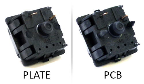
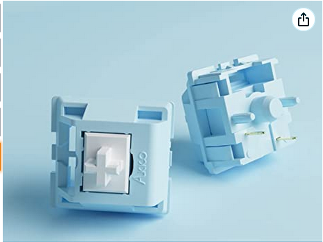
When I was building the BOM I found that its actually really hard to find, bulk key switches at a reasonable cost. This is no surprise given the cost of a new mechanical keyboard these days but its absolutely laughable the lack of cloned switches that are available in the major electronics suppliers. This may differ vastly if you look into whats available in the Asian suppliers but I did take a quick glance at LCSC and only really found stuff like that in limited supply. So at this point I figure I can put the base switch in the BOM, and let people know you can get a switch set (or get really lucky and find a keyboard used with PCB mount switches) for much cheaper if you just search places like amazon / ebay / AliExpress. The important piece of this is you need a PCB mount MX style switch:
![]()
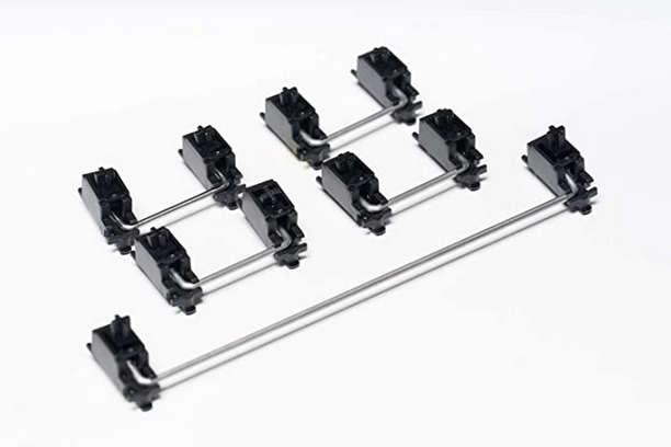
The importance here is that PCB mount switches have 5 pins, and plate mount only have 3. You can get away with plate mount switches but without the 3 point positioning rail across the center you will have a very hard time lining them up; so this detail is very important if you want the keyboard key caps to fly independently of each other. I went with this set of knock off switches from amazon, which came out to about .43 cents per switch, for comparison, bulk cherry MX Black switches are .99 cents, before shipping. Another important consideration is the space bar stabilizer. Again what is required is a PCB mount "snap in" stabilizer:
![]()
a really good guide from click and switch, explains the ins and outs of stabilizers I found a affordable kit here at amazon, you do have to buy a full set when you only need the 6.25 spring and two stabilizers but I could not find this as a single part on any of the parts distributors. These simply snap in to the PCB, the footprint in the board is correct for snap in cherry type stabilizers but others might fit with some research. If there is a good source of these that I can include in the BOM for assembly it would be very useful to know that, but for now I consider it as part of the key cap set and it comes down to preference.
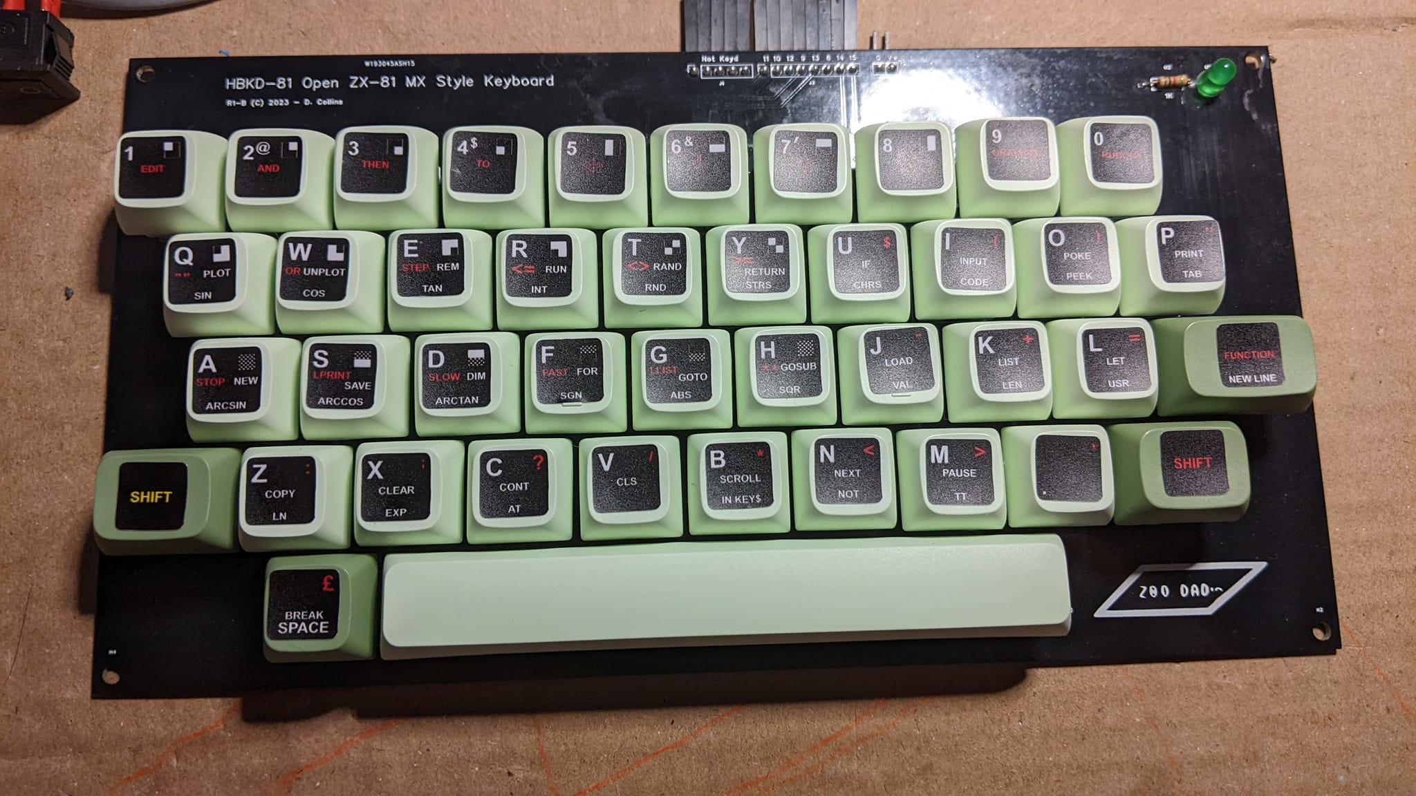
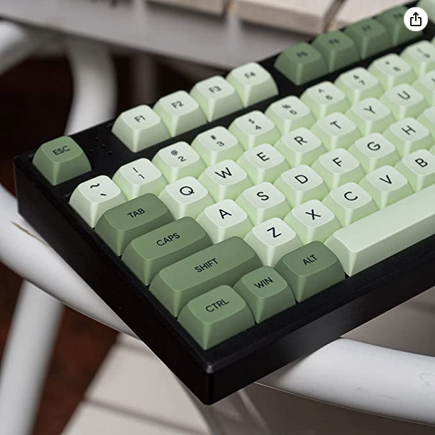
speaking of key caps, since the design allows for use of a out of place salvaged key caps from a 60% mechanical keyboard, we should talk about key cap profile. The profile of a keyboard defines the height of the switch across a row:
![]()
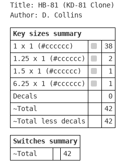
Here, on my prototype I used XDA profile key caps, and the reason is clear if you look at the above graph. Since the height of the switch does not change from row to row - there's little issue with moving two of the keys from the bottom row to the 2nd from the bottom, or the top row to the middle it makes no difference. Since were using the stickers to recreate the key legends we don't actually care what the original key caps say because they will be covered with a high quality sticker / decal. When I ordered key caps for the keyboard that I built I again used amazon but you can use any XDA profile key-cap set as long as they have a 60% reduced space bar, the following table may help:
![]()
The table was exported from keyboard-layout-editor.com, and was built before I had decided on going with the decal set.
Final reflections and whats next:
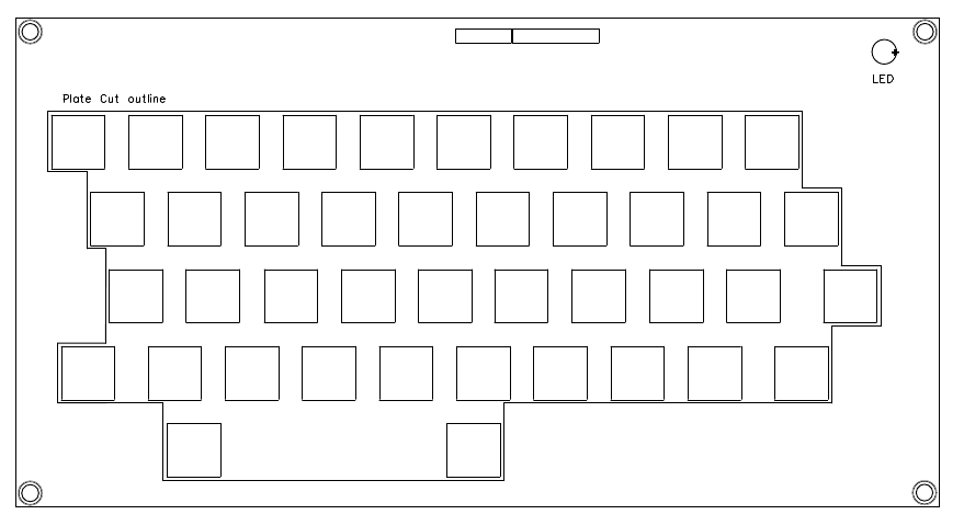
So up next is cutting the case for the computer and fitting everything in place so I can make measurements for cad drawings that can be used to send to a manufacturer to have them cut:
![]()
I drew a outline in my EDA software using the documentation layer for the cut lines. Next I have to make my own drill and cut templates so I can lay it all out and mark up the test panels. I'll be working with a Dremel to make these cuts, and to be honest I am kind of dreading doing it but we will get it figured out. Worst case I will go to the hardware store and get plexiglass cut to the correct sizes and make the cuts with a manual hack saw blade.
So far I am very pleased with the way the project has come out. I am excited to work on the panels and learn some 2d cad. I would really like that phase to come out as nice as the last but no project can go off without a hitch, we just haven't found ours in this one yet.
Thanks for sticking it out to this point, if anybody has questions feel free to leave a line here or in the usual places. I'll be updating all of the various places you can get at this project over the next few days. Feel free to let me know if you can't find something but odds are I just haven't uploaded it yet.
-
Parts / case selection getting all the bits together.
03/05/2023 at 03:41 • 0 comments![]()
OK, so I settled on the PT-10 from Pac-Tec. I chose this case because:
- It is still in production and in the electronics suppliers (at least in the US where I reside.)
- all of the panels can be defined in 2d cad drawings, which i can later send to production in any material I like, for instance transparent or black plexiglass / acrylic
- The cost for the case without panels is approximately 19 dollars US (before shipping, which in the continental us is about 10 dollars).
- the non-production kit with all of the panels installed as blanks (for making the prototype) comes in at approximately 44 dollars + 10 dollars shipping before VAT which is about 2 more dollars.(yikes!)
- The hope is to get the cost of the case, and pre-cut inserts down to around 50 dollars -- so if you can get the PCB / panels shipped at the same time the total cost for the case with the keyboard should be well under 100, this is pending the cost of fabrication for these things which I am still new at; and have no idea what all the costs are, but the lions share of the price is in the shipping.
For switches I piked these interestingly colored knock offs found off amazon:
![]()
These have the plastic PCB mount stand offs, a set of 45 was 18 dollars on amazon. This is by far the cheapest switch on amazon -- you could most likely source cheaper from the electronics supplier and I am still not 100% sold on through hole switches - I still think I can find a surface mount switch for considerably less. but doing the routing on a single layer, PCB without some way of managing crossing tracks is difficult. Consider also the initial membrane was two layers to begin with.
For the key caps i settled on a simple PBA retro looking switches:
![]()
The key caps have a XDA profile so the key height does not change from one row to the next. This is super important because we are moving some of the keys from their rows and we want it all to line up properly. So later on, builders who care about this detail will need source keys with the same profile. Its a standard so I am certain there are keyboards out there with this particular profile.
I am still on the fence for my ZX81 build as to weather or not to use a full picoATX power supply (which would have all the niceties like over-volt protection, reverse current protection as well as a real 3.3v rail for mods. Later on when I do the terminal build I will definitely go for this, as it makes the case considerably more useful for a larger range of single board computers.
Now it's just sit back and wait for all the parts to come in. Most of the small bits are here as of today. The case will be here mid week, and I also ordered a sticker set for the key caps to put over top for the ZX81 build. hopefully soon as I am chomping at the bit to get the wheels turning on this project!
-
Initial Gerbers / Mock Layout
02/27/2023 at 06:03 • 0 comments![]()
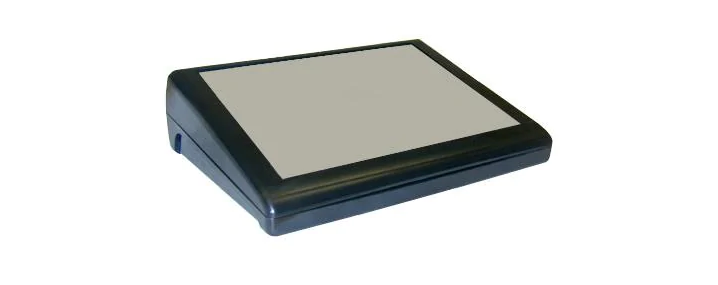
A simple Idea, make a case for my orphaned ZX81. If you have been following along with my little side project I have been restoring a ZX81 motherboard. With that task mostly complete I now need a case to keep the little guy in. searching the web I stumbled across this little gem over at the Timex/Sinclair web site :
![]()
The Suntronics KD-81. WOW. I fell in love with this little thing, and its a big time on my want list but since searching for KD-81 keyboard on eBay landed me no results I guess I'm stuck with a reasonable facsimile.
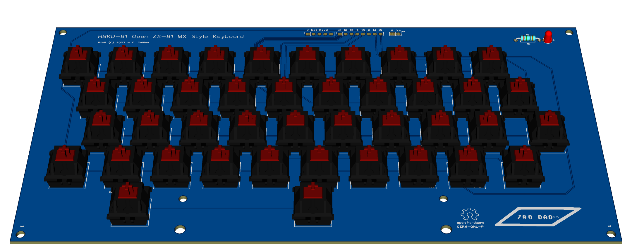
![]()
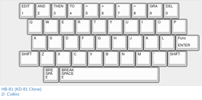
I knocked this together over the last week and am currently working on getting it to production in order to test things out. since the ZX81 keyboard is a fairly simple, well documented circuit I won't bore you with the details other than to say it uses MX style switches, has a power led and space for a current limiting resistor. Additionally, we are using standard sized key caps, in the case that somebody wants to piece together salvaged key caps and go the sticker route. The larger keys are half sized, SHIFT being a standard size of a ALT key, the ENTER key being the standard size of a tab or backslash "\" key.
It might be a few weeks till I get all the bits and bobs together on this one, even though its meant to be cost effective, keyboards are still fairly expensive when made in a volume of 1. The most expensive part being, shipping for anything we don't have to hand and switches. I want to try to salvage as much as I can from existing tech if I can get it cheaper than just buying on the markets.
HBKD-81
An open, replacement case design for a wedge style home computer