 Albertas Mickėnas
-
Firmware overview
03/09/2023 at 19:41 • 0 commentsFully functional firmware supporting low power operation is provided and can be found in the github repository.
Since we are using deep sleep, all the action happens in the setup function, only few state bytes are kept in RTC memory that is retained between wakeups:
void setup() {
  Serial.begin(9600);
  Serial.println(String("Hello, is_first_run:") + is_first_run);

  SensorsInit();
  SensorsPowerOn();
  SensorReadings new_readings = SensorsRead();
  if (is_first_run) {
    sensor_readings = new_readings;
  }
  SensorsPowerOff();

  if (is_first_run || sensor_readings != new_readings) {
    DisplayInit();
    NetworkInit();
    DisplayData(new_readings, is_wifi_connected);
    Serial.println(String("is_wifi_configured:") + is_wifi_connected);
    if (is_wifi_connected) {
      MqttSetup();
      MqttPublish(new_readings);
    } else {
      Serial.println("Wifi not connected");
    }
    sensor_readings = new_readings;
  }
  is_first_run = false;
  DeepSleep(DEEP_SLEEP_TIME);
}
WifiManager library is used to support WiFi credential provisioning.
GxEPD library is used to access the display.
Examples available:
- Basic display test
- Basic I2C test
- Full example of humidity monitor, includinf WiFi provisioning and posting to MQTT
- Full example of soil moisture monitor, includinf WiFi provisioning and posting to MQTT
- Weather forecast example
- BLE peripheral example
-
Design walkthrough
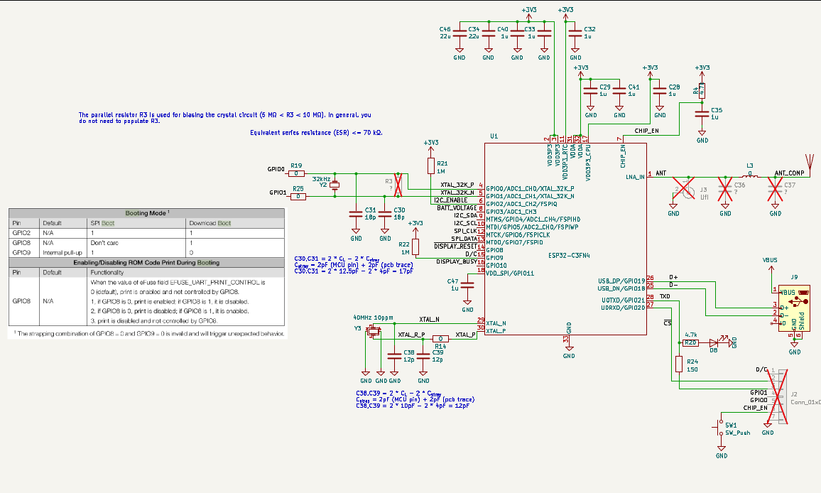
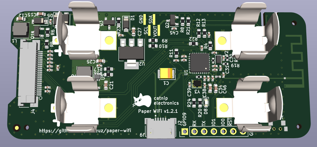
03/03/2023 at 14:52 • 0 commentsESP32C3 supporting components is basically just following ESP32C3 Family Hardware Design Guidelines. There's a footprint for 32kHz crystal, but since it's not supported in Arduino environment, also pins are broken out as GPIO.
Display power conditioning circuit is also provided in a datasheet from GooDisplay
Power section is designed to take in both USB and battery power. U5 is a boost converter and Q3 is responsible for disconnecting batteries when powered form USB and provide reverse polarity protection.
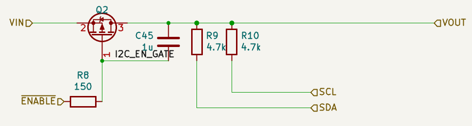
Power to I2C sensors is switched via transistor to save some Coulombs -
Add WiFi
03/03/2023 at 14:40 • 0 commentsSo I have decided to add WiFi to my display. It will not compromise display part, but will make it a more versatile tool for my sensor experiments. Also it adds another dimension to the project - it can not only display sensor data, but also whatever data pulled from the net!
I have chosen ESP32C3 as the main micro-controller because of two reasons - it's low power and it's risc-v based - I wandered how good risc-v support is in the standard Arduino tool chain. Also ESP32C3 has in build USB-to-serial peripheral saving the need to design in USB-to-serial converter chip.
Unfortunately, 2450 batteries had to go as they couldn't support high current spikes during WiFi communication. Thus AA batteries had to come in. I hesitated a bit between AA and AAA, but opted for AA to have more juice, meaning more communication and more display updates.
I have chosen to use bare ESP32 chip and add printed 2.4GHz antenna to the PCB mainly to use this as an opportunity to learn something, also I didn't want to change the size of the PCB a lot and module is a bit bulky. I still have to go to RF lab to perform antenna measurements, I have just ordered bare PCBs with U.fl connector added for this specific task.
-
So I needed a display for sensor data
03/03/2023 at 13:46 • 0 commentsSometimes having sensor data piped over RF to your database or to your console is not enough. Sometimes you want a big display displaying your numbers you could just throw a look at. Sometimes you want to package your sensor and a display to a person at industrial facility so they could quickly measure something without involving connectivity and computer.
Thus 2 years ago I started on a journey to design myself a display like that. The device had to be battery operated - wall plug devices are a thing of the past, so e-paper was an easy choice for the display technology - low power, high contrast, relatively high resolution.
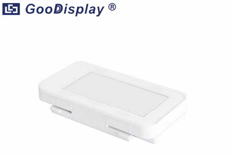
I am not very good at mechanical design, so I wanted to piggyback on something that's available, thus I stumbled on electronic label enclosure kit available from GooDisplay
This case has features allowing for two 2450 coin cell batteries, I hoped to sneak in whatever sensor wires I need via strategically drilled hole.
So I have designed a PCB specifically for this case.On the top left you can see e-paper display power related components. Top right is a boost converted for voltage regulation and bottom right is an ATSAMD21G18A micro-controller. The choice for the micro-controller was mainly steered by availability and good software support available from Adafruit for their feather boards - I wanted to take advantage of that.
After finishing the design I put it on a shelf as pandemic was in full swing, so I had another things to worry about, but after some time I came back and had another look - all this effort for just adding a display? Maybe I could beef it up somehow with additional functionality?
 Display power conditioning circuit is also provided in a datasheet from GooDisplay
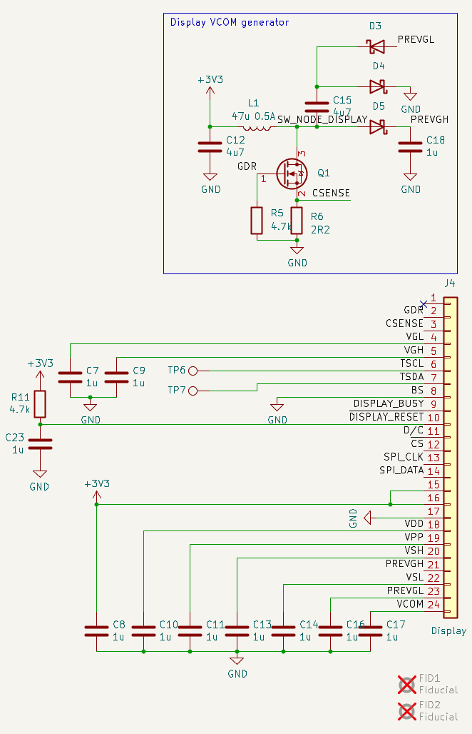 Power section is designed to take in both USB and battery power. U5 is a boost converter and Q3 is responsible for disconnecting batteries when powered form USB and provide reverse polarity protection.
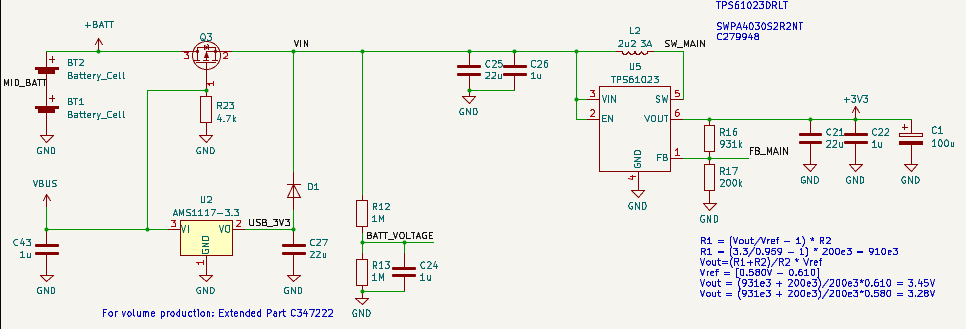
 This case has features allowing for two 2450 coin cell batteries, I hoped to sneak in whatever sensor wires I need via strategically drilled hole.
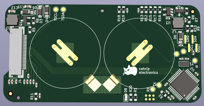 On the top left you can see e-paper display power related components. Top right is a boost converted for voltage regulation and bottom right is an ATSAMD21G18A micro-controller. The choice for the micro-controller was mainly steered by availability and good software support available from Adafruit for their feather boards - I wanted to take advantage of that.