Ulrich
-
Error on the RTC found
03/20/2023 at 21:21 • 0 commentsFound a last minute bug before production
R25 was missing: WIthout it the RTC would have fired Interrupts on any swipe.
No I am more confident on operation of this RTC.
-
Last minute Changes on the PCB before production
03/13/2023 at 20:25 • 0 commentsTonight was a very rainy night in Stuttgart.
Therefore I had some spare time to add some more documentation on the Project Github Page.
While doing so I found some last minute changes on the PCB.
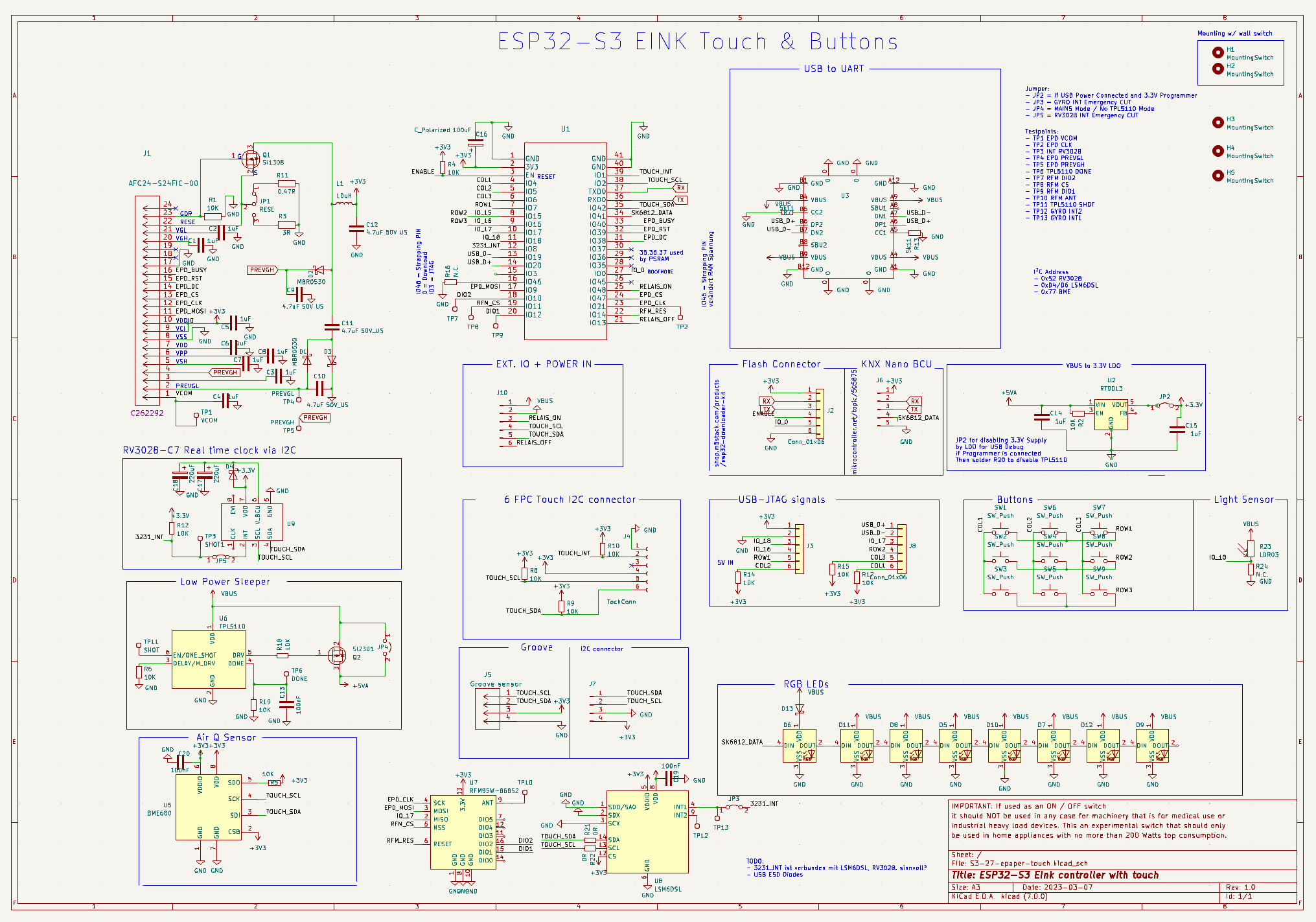
For Testing and Hardware Bring Up I added some more Testpoints.
New Testpoints
- TP1 EPD VCOM
- TP2 EPD CLK
- TP3 INT RV3028
- TP4 EPD PREVGL
- TP5 EPD PREVGH
- TP6 TPL5110 DONE
- TP7 RFM DIO2
- TP8 RFM CS
- TP9 RFM DIO1
- TP10 RFM ANT
- TP11 TPL5110 SHOT
- TP12 GYRO INT2
- TP13 GYRO INT1Even more useful are Solder Jumper points for enabling or Disabling Features
Jumper:
- JP1 = Selector for EPD Display
- JP2 = If USB Power Connected and 3.3V Programmer
- JP3 = GYRO INT Emergency CUT
- JP4 = MAINS Mode / No TPL5110 Mode
- JP5 = RV3028 INT Emergency CUTSchematics have been updated
![]()
-
Case is slowly in progress
03/12/2023 at 21:07 • 0 commentsThis is my first Autocad case design.
Lots of struggling so far and do not know how this works at all.
Lets see how it looks in the end.
-
LOW Power Consumption when not in use
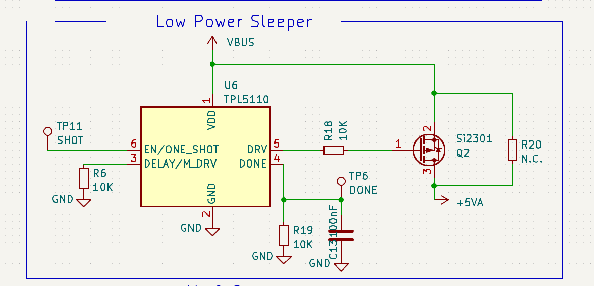
03/12/2023 at 09:31 • 0 commentsTo reduce the Current consumption I decided to design a POWER GATEING CHIP into my design.
This Power Gateing Chip can disable the complete Power supply with an MOSFet.
With this little trick the Quiescent current drops dramtically when the wallswitch is not in Use.
According to the datasheet this leads to a low current of 50nA when the design is not in use.
![]()
This RTC Chips wakes up based on the the resistors designed around the Delay Pin.
With the Resistors R6 you may define the sleep period where the Mikrocontroller shall not get any POWER.
Once operation of the wall switch is finished the Microcontroller may send a "Done" Signal via TP6 to the Power Gateing Chip. This enables low power sleep until an ext Event is triggered via Shot or a timer has run low.
The time of the timer may be set statically via R6.
If connected to the 230 V MAINS power(via an ext. power supply) you may use it in always on mode: Therefore R20 is introduced. This may enable the Power Supply at all times.
-
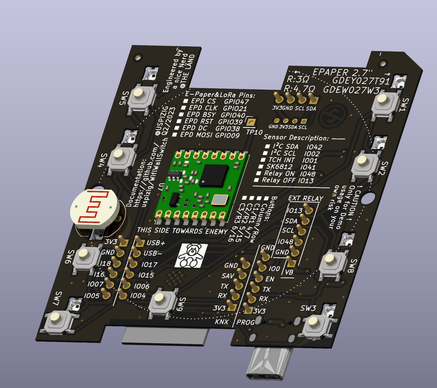
Added a LDR for Ambient Light Detection
03/12/2023 at 09:18 • 0 commentsThis morning I came up with a NEW idea:
How about adding a Light Detection Resistor?
With this sensor you may get more data about you ambient situation.
![]()
Examples:
- How bright shall a Light shine after activation?
- How fast shall the light switch ramp up LUX?
- Can I reduce brightness to an optimum level?
- Are my kids still awake or are they still using any torch light in Bed?
- What is the distribution of light during the day?
- Transmit Data via MQTT to a central server
AirQ&EarthQ-LoRa EInk WallSwitch
A Module that fits in a typical Wallswitch with Air Quality, EarthQuake Detection and Ultra Low Power Sleep Mode + an Touch EInk Display