Just4Fun
-
Two layers PCB!
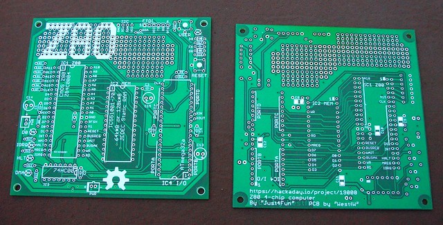
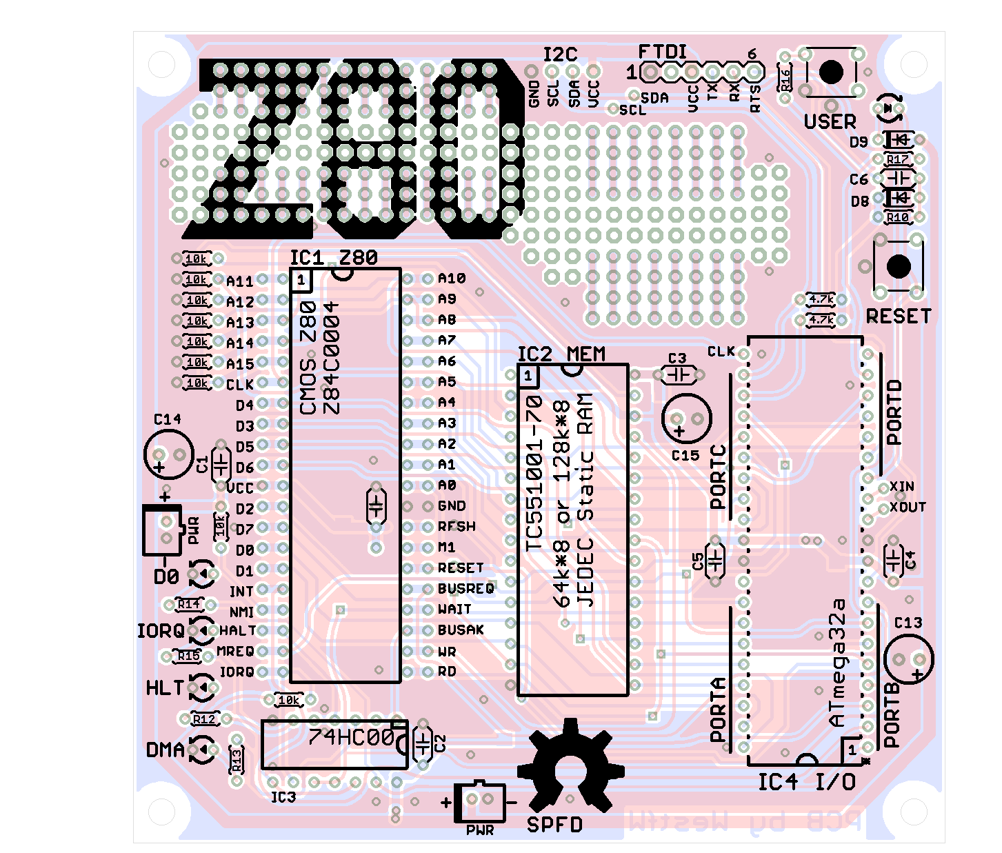
02/06/2017 at 20:44 • 0 commentsThanks to Bill Westfield now we have a beautiful ready to made PCB!
![]()
I've uploaded in the Files section all the Eagle files (schematic + PCB) zipped as 4chipZ80-Eagle-PCB.zip.
There are two versions, the first one with some little bugs and a second one with the needed corrections (see the "readme" file inside the zip for the explanations).In any case I suggest to check at the Bill GitHub repository here for any update/information before sending it to a service (so you are sure to use the last updated version...).
![]()
-
New iLoad boot mode and an automated Assembler toolchain
01/31/2017 at 20:36 • 7 commentsThis new IOS release (S221116_R230117_Z80.ino in the Files section) brings a new dual-boot mode. Now it's possible choose if boot with the usual Basic or use the new iLoad boot mode.
iLoad (S260117.asm in the Files section) is an Intel-Hex bootloader that allows to load from the serial port a binary program using the Intel-Hex format, and execute it. I've used a large part of the source from this site.To select a boot mode just push the Z80-MBC Reset button and immediately after push the User button at least until the User led turns off.
The selection works as a toggle switch, and is stored in the EEPROM.
Here it is a video that shows how to switch:Using the iLoad boot mode it's possible to automate all the process from the source to the execution in the target.
This video shows an automatic Assembler toolchain; only one command from the source assembler to the execution on the target (the source file BlinkDemo.asm used in the video is in the File section):HOW TO SET UP AN "AUTOMATED" ASSEMBLER TOOLCHAIN
What you need to do:
- Set up a Windows host or a VM (Virtual Machine). I've used a Windows XP SP3 VM onto a linux host;
- Load the Windows driver for your serial-USB adapter. Remember that your dongle *must* have the DTR signal;
- Create a working directory where to store the assembler sources, the assembler program and the two batch files (A.BAT and L.BAT) in the asmbatch.zip file (see the File section). With a text editor search the line:
"C:\Program Files\teraterm\ttermpro.exe" /c=3 /BAUD=9600 /w="Z80-MBC Terminal" /m=LoadZ80.ttlinside A.BAT and L.BAT and verify that both the path and the COM number (/c=3 means COM3) meet your system; - Download and copy in the previous directory the TASM v3.2 assembler from here. The on-line manual is here;
- Download and install the "Tera Term" terminal emulation from here;
- Set up Tera Term. From the Tera Term "Setup" menu select "Serial port..." and configure the parameters for your COM<n> connection to your serial-USB adapter. Set 9600 Baud, 8N1, Flow control none, Transmit delay 40ms/line. Save configuration with "Save setup..." from the "Setup" menu;
- Copy the file LoadZ80.ttl (see Files section) in the "Tera Term" installation directory, where it is installed the main file ttermpro.exe (for a standard installation for an English Windows version should be "C:\Program Files\teraterm");
- Open the file LoadZ80.ttl with a text editor and go to line 10. Edit the "setdir" parameter to meet your working directory path and name created at point 3. on your system, and save the file;
- Open the DOS command line and go in the working directory (using the CD dos command), attach the serial-USB dongle to the Z80-MBC and for a VM "connect" the dongle to the emulated usb of your VM. All done!
Now it's time to check if it is all ok. From the DOS command line give the command: "A blinkdemo.asm" to check if all the toolchain works as in the video. To load the last compiled program give the command "L" without parameters. To load a specific intel-hex file give the command "L <filename.hex>".
Close Tera Term before every new upload.
iLoad behavior
Please remember that iLoad will take the first address of the intel-hex stream as the starting address of the program, and after the loading will jump to it.
iLoad will check the hex stream for errors, and protects itself if "someone" try to load a program (or a part) over it ("illegal address" error). -
GPIO Expansion Module
01/22/2017 at 13:50 • 2 commentsThis is the first add-on module for the Z80-MBC. It is a 16x GPIOs expansion module based on a MCP23017 IC, and can be easily connected to the Z80-MBC using the IOEXP connector (based on a I2C serial interface), of course on a breadboard...
![]()
In the Files section I've added the schematic (A080117.pdf) and all the KiCad4 files (A080117 Kicad4.zip).
There is also a new release of the IOS (S221116_R200117_Z80.ino) that takes care of it. During the boot phase, if the GPIO expansion module is found, a specific text is displayed:![]()
No configuration is needed, just plug it.
Here is a short demo video:Each GPIO can be configured as input or output, and for each single input it is possible activate a 100K pull-up resistor. Of course this can be done from the Basic language, using new "virtual" I/O addresses as a language extension (if the module is not present, these I/O addresses are simply ignored):
New WRITE I/O addresses:0x03: // GPIOA write (GPIO Expansion Module): // I/O DATA: D7 D6 D5 D4 D3 D2 D1 D0 // --------------------------------------------------------- // D7 D6 D5 D4 D3 D2 D1 D0 GPIOA value (see MCP32017 datasheet) 0x04: // GPIOB write (GPIO Expansion Module): // I/O DATA: D7 D6 D5 D4 D3 D2 D1 D0 // --------------------------------------------------------- // D7 D6 D5 D4 D3 D2 D1 D0 GPIOB value (see MCP32017 datasheet) 0x05: // IODIRA write (GPIO Expansion Module): // I/O DATA: D7 D6 D5 D4 D3 D2 D1 D0 // --------------------------------------------------------- // D7 D6 D5 D4 D3 D2 D1 D0 IODIRA value (see MCP32017 datasheet) 0x06: // IODIRB write (GPIO Expansion Module): // I/O DATA: D7 D6 D5 D4 D3 D2 D1 D0 // --------------------------------------------------------- // D7 D6 D5 D4 D3 D2 D1 D0 IODIRB value (see MCP32017 datasheet) 0x07: // GPPUA write (GPIO Expansion Module): // I/O DATA: D7 D6 D5 D4 D3 D2 D1 D0 // --------------------------------------------------------- // D7 D6 D5 D4 D3 D2 D1 D0 GPPUA value (see MCP32017 datasheet) 0x08: // GPPUB write (GPIO Exp. Mod. ): // I/O DATA: D7 D6 D5 D4 D3 D2 D1 D0 // --------------------------------------------------------- // D7 D6 D5 D4 D3 D2 D1 D0 GPPUB value (see MCP32017 datasheet)New READ I/O addresses:
          0x03:
            // GPIOA read (GPIO Expansion Module):
            //                I/O DATA:    D7 D6 D5 D4 D3 D2 D1 D0
            //                            ---------------------------------------------------------
            //                             D7 D6 D5 D4 D3 D2 D1 D0    GPIOA value (see MCP32017 datasheet)
            //
            // NOTE: a value 0x00 is forced if the GPIO Expansion Module is not present

          0x04:
            // GPIOB read (GPIO Expansion Module):
            //                I/O DATA:    D7 D6 D5 D4 D3 D2 D1 D0
            //                            ---------------------------------------------------------
            //                             D7 D6 D5 D4 D3 D2 D1 D0    GPIOB value (see MCP32017 datasheet)
            //
            // NOTE: a value 0x00 is forced if the GPIO Expansion Module is not present
And here is the Basic program used in the video (the HW wiring is shown in the comments):
1 REM * * * GPIO EXPANSION MODULE (A080117) DEMO  * * *
2 REM
3 REM (USER Key -> slow led, GPIO-A(9) Key -> fast led)
4 REM --------------------------------------------------
5 REM Demo HW wiring (see A080117 schematic):
6 REM
7 REM   GPIO-B
8 REM    (J3)
9 REM   +----+   LED
10 REM  | 2  |--->|---+
11 REM  | 3  |--->|---+      RESISTOR
12 REM  | 4  |--->|---+        680
13 REM  | 5  |--->|---+-------/\/\/-----o GND
14 REM  | 6  |--->|---+
15 REM  | 7  |--->|---+
16 REM  | 8  |--->|---+
17 REM  | 9  |--->|---+
18 REM  +----+        |
19 REM                |
20 REM                |
21 REM  GPIO-A        |
22 REM   (J4)         |
23 REM  +----+   LED  |
24 REM  | 2  |--->|---+
25 REM  | 3  |--->|---+
26 REM  | 4  |x
27 REM  | 5  |x
28 REM  | 6  |x
29 REM  | 7  |x     PUSH BUTTON            RESISTOR
30 REM  | 8  |x        ---                   1K
31 REM  | 9  |---------o o------------------/\/\/-----o GND
32 REM  +----+
33 REM
34 REM
35 REM
36 REM --------------------------------------------------
37 REM
38 REM Set MCP23017 GPIOB all pins as output (IODIRB=0x00)
39 OUT 6, 0
40 REM Set MCP23017 GPIOA 0-1 as output, others as input (IODIRA=0xFC)
41 OUT 5, 252
42 REM Set MCP23017 GPIOA 2-7 pull-up resistor on (GPPUA=0xFC)
43 OUT 7, 252
45 REM Left Shift user funcion definition
50 DEF FNLSH(X)=((X*2) AND 255)
55 REM Init GPIO output ports
60 OUT 3, 0 : REM Clear MCP23017 GPIOA port
62 OUT 4, 0 : REM Clear MCP23017 GPIOB port
64 GOSUB 700 : REM Set slow shift
68 REM Main
70 A=1
80 FOR I=0 TO 7
90 OUT 4, A : REM Write to MCP23017 GPIOB port
100 GOSUB 500
110 A=FNLSH(A)
120 NEXT I
130 OUT 4, 0 : REM Clear MCP23017 GPIOB port
135 A=1
140 FOR I=0 TO 1
150 OUT 3, A : REM Write to MCP23017 GPIOA port
160 GOSUB 500
170 A=FNLSH(A)
190 NEXT I
200 OUT 3, 0 : REM Clear MCP23017 GPIOA port
210 GOTO 70 : REM Play it again, Sam...
220 REM
500 REM * * * * * DELAY SUB
505 FOR J=0 TO K
507 IF INP(0)=1 THEN GOSUB 700 : REM Read USER key
508 IF (INP(3) AND 128)=0 THEN GOSUB 600 : REM Read MCP23017 GPIOA 7 key
510 NEXT J
520 RETURN
530 REM
600 REM * * * * * SET FAST SHIFT SUB
610 K=1
620 OUT 0, 1 : REM USER led ON
630 RETURN
640 REM
700 REM * * * * * SET SLOW SHIFT SUB
710 K=30
720 OUT 0, 0 : REM USER led OFF
730 RETURN
--> Important Note: If you use a terminal emulator to send the file to the Z80-MBC, configure it to add a 40ms delay each "end of line". Because Arduino bootloader "environment" doesn't manage any handshaking on the serial port, this is needed for a correct file transfer.
-
SOFTWARE INTERNALS: The boot process
01/04/2017 at 14:35 • 0 commentsHere is a description of the two phases boot process and the sources of the Loader and the uBIOS + Basic (as requested by some people).
At power on, the Atmega32A uses a DMA access to SRAM to copy the loader in the upper memory address space.
Because the loader is small, only a limited number of address lines are requested, saving some GPIOs for others tasks.When the Atmega32A completes the DMA loading phase (first phase), it releases the Z80 bus and resets the Z80 CPU that starts to execute the loader from SRAM starting at address $0000.
Then the loader relocates itself at the bottom of the memory address space and it loads from the Atmega32A (this time used as a "virtual" sequential ROM in the I/O address space) the uBIOS + Basic image (second phase).After this second load phase it jumps to the starting address of the uBIOS + Basic image, and executes it.
Inside the Arduino sketch you can see the two hex arrays. The smaller one is the Loader image, the bigger one is the uBIOS + Basic image.
In the Files section I've added the Loader source (S091116.asm) I wrote from scratch, and the two files (uBIOS and Basic) I took from the Grant's site. I've modified the first one (the one I've called uBIOS) that contains the I/O routines due the different HW design. In particular I changed the I/O addresses, the init code made for the original ACIA and the code to menage the internal registers of the ACIA. I've changed also the code that manages the ACIA serial handshaking because not needed here (the serial is managed inside the Atmega32A by the Arduino bootloader "environment") . You can easily see any modification in the source (S121216.asm) because they are marked with the string "Z80-MBC:" in the comment.I left the Basic interpreter (basic.asm) untouched (for now, until I need some custom commands...).
A 4$, 4ICs, Z80 homemade computer on breadboard
No iron, no cry! Build a mini 4MHz Z80 64kB RAM system with Basic and Forth interpreters, CP/M 2.2, QP/M 2.71, Assembler and C toolchains