-
2024 Update
05/10/2024 at 16:39 • 0 commentsI have started a new project entitled Narcissus 12.0 which you can, of course, find right here on Hackaday.io, Although I'm not currently doing anything new with the Altair as of right now, I do eventually want to be able to play "Global Thermonuclear War" in the classic WOPR-Wargames style on it - which will, of course, require some kind of chatbot that is ideally capable of running on 8080, i.e.,, maybe something that works like Eliza, on the one hand, but which also provides a front end to a CP/M like operating system, yet which offers more functionality - let's say - like Busy Box.
Now most of this might turn out to be quite easy to do if I would just simply get the Altair running in terminal mode, that is by burning some EPROMS with the stuff that I have so far, like the MIDI codes, and the PS/2 interface. This is because I also have an 80x25, late 7'0s vintage video board that, while it needs some repairs, might be able to be made to work again. Then maybe I could run the WHOPPER code, when I get it written, perhaps on a Raspberry Pi, or Propeller module, as previously discussed. It is always best to try to push the 8080A original hardware to its absolute limits, of course.
So, yes. hopefully, I will be doing something with the Altair again, soon - but in the meantime, and on the software side of things, further development will be proceeding along the lines of my newest project, as stated at the beginning of this post. Thanks for checking in!
-
Additional notes on interfacing the 6850 UART
04/23/2023 at 05:39 • 0 commentsHere again, is the code just discussed for reading the serial port and then displaying the data on the status LEDs, but now it has been split into an initialization section and a main loop. Obviously, we should also want to do something with the data as it is input like storing it in a buffer, but this is a very useful piece of code that can be used for testing purposes.
INIT1:
  LDA  0x1f   ; reset the UART
  OUT  0x0a   ; configure for eight-bits + odd parity + one stop bit
  LDA  0x1c   ; at 1X clock rate
  OUT  0x0a
  RET          ; or HALT?

LOOP:
  IN   0x0a   ; get port status byte
  AND  0x01   ; mask for Rx status bit
  JZ   LOOP
  IN   0x0b   ; read the data
  OUT  0xff   ; display front panel LEDs
  JMP  LOOP
  NOP
  NOP
It would also be nice if this code were interrupt driven. Changing the infinite loop to a return at the end gives us a callable function. Then we need to call INIT1 to initialize the port, and then we could call GETCH, whenever we want to get a character. This works for polled I/O, that is if we don’t mind having our application hung while waiting for input, when in fact we want if to be able to do other things, like maintaining time code, streaming MIDI, and so on. Of course, if we are going to be working in a high-level language such as Pascal, C, or even C++, then we will probably want some functions that we could call, and that have names like PEEK, GETC, READ, etc.
INIT1:
  LDA  0x1f   ; reset the UART
  OUT  0x0a   ;
  LDA  0x9c   ; for PS2 kbd configure for 8-bits + odd parity + 1 stop bit
              ' at 1X clock rate, and generate interrupts on RxByte
              ; FOR MIDI data - there should be NO PARITY - and the
              ; clock rate is 16X - so change this to LDA 0x95
  OUT  0x0a   ;
  RET

PEEK:
  IN   0x0a   ; get port status byte
  AND  0x01   ; mmask for Rx status bit
  JNZ  GETC
  LDA  0xff   ; return EOF if port not ready
  RET

GETC:
  IN   0x0b   ; read the data
  OUT  0xff   ; display on front panel LEDs
  RET
Now let’s rewrite what we have so far to read data from the PS2 keyboard using interrupts. According to the 6850 UART data sheet, setting bit 7 enables the receive port interrupt, and on the MITS 88-2SIO serial board, the IRQ level is set by a jumper wire on the board so as to point to an octal address in the zero page, 0X0, giving us just eight bytes to store the interrupt service routine. Since we have 24 bytes so far, it should be obvious that the ISRs will have to go somewhere, and that the zero-page locations will contain a simple dispatch function. The 88-VI-RTC board will also need to be configured to allow interrupts at the appropriate level, and so on.
At a certain point, we will also need to start counting the number of CPU cycles that are used in servicing the read request. MIDI messages frequently contain multiple bytes, which are generally sent consecutively, in 8-bit format, with one stop bit, and no parity. For example, according to Wikipedia, a full MDI time code message looks something like this:
F0 7F 7F 01 01 hh mm ss ff F7
This will most likely be sent by a remote device in burst mode if our device is receiving the time code. So, although receiving bytes from a keyboard might seem quite leisurely, with MIDI streaming at 31250 bps, we will need to be able to handle up to 3125 bytes per second, which gives us a “budget” of about 320 microseconds per byte received, which will allow for no more than 160 8080A instructions to be executed, given a 2 MHz clock, or else we risk a buffer overflow since the 6850 can only buffer one already received character, in addition to any that are presently being clocked in.
The manual for the MITS 88-VT-RTC includes some sample code for creating a simple clock that is interrupt driven, and that allows the current time to be read from BASIC. Using this code as a starting point, why not rewrite it to be able to SYNC to a remote time code source, as well as be able to free-run it as a MIDI time code streaming device? Then there is also the issue of the MIDI beat clock, which is a different animal altogether, but that is another clock source that generates twenty-four MIDI ticks per quarter note according to whatever the tempo is in the current musical passage.
Oh, and there is also the “running time code” which is a series of messages that are interspersed as four separate sub-messages per frame of regular time code, so these need to be decoded if we are receiving them, as well as being created and then streamed correctly if we are running a time code generator.
Floating point arithmetic would also be nice to have so that any “old-fashioned menu-driven console mode application” might possibly be able to be configured to generate appropriate MIDI clock pulses for tempos that have decimal values, like 123.14 BPM, or whatever if that is so desired. Fortunately, I have a set of floating-point routines that I wrote in C++ that could be made to work on “any architecture” for which there is a C or C++ compiler available, even hypothetical machines that might only have logical shift and bitwise NOR operations. So even if I digress, as a hint of things to come, here is one way to do floating point multiplication, which seems to work – but which hasn’t been rigorously tested:
real real::operator * (real arg)
{
    short _sign;
    real result;
    short exp1 = this->exp()+arg.exp()-127;
    unsigned int frac1, frac2, frac3, frac4, fracr;
    unsigned short s1, s2;
    unsigned char c1, c2;
    _sign = this->s^arg.s;
    frac1 = this->f;
    frac2 = arg.f;
    s1 = (frac1>>7);
    s2 = (frac2>>7);
    c1 = (frac1&0x7f);
    c2 = (frac2&0x7f);
    frac3 = (c1*s2+c2*s1)>>16;
    frac4 = (s1*s2)>>9;
    fracr = frac1+frac2+frac3+frac4;
    if (fracr>0x007FFFFF)
    {
        fracr = ((fracr+(1<<23))>>1);
        exp1++;
    }
    result.dw = (fracr&0x007FFFFF)|(exp1<<23)|(_sign<<31);
    return result;
}
That of course assumes that you have 8/16/32 bit integer, addition, subtraction, multiplication, etc., and that is another bear altogether to implement
inline DWORD square(unsigned short r1)
{
    DWORD t0,result;
    DWORD t1, t2, t3;
    unsigned char highbyte, lowbyte;
    lowbyte = r1&0xff;
    highbyte = (r1&0xff00)>>BYTESIZE;
    t0 = (lut1[highbyte]<<WORDSIZE)|(lut1[lowbyte]);
    t1 = mult8(highbyte,lowbyte);
    t2 = t1<<(BYTESIZE+1);
    t3 = add(t0,t2);
    result = t3;
    ASSERT(r1*r1==result);
    return result;
}

inline unsigned short mult8 (unsigned char c1, unsigned char c2)
{
    unsigned short s0, s1, s2, s3, s4;
    if ((c1==0)|(c2==0))
        return 0;
    if (c1==1)
        return c2;
    if (c2==1)
        return c1;
    s0 = (unsigned short) add(c1,c2);
    s1 = (unsigned short) sub(c1,c2);
    bool m_odd = (s0&0x1?true:false);
    bool m_neg = (s1&0x8000?true:false);
    if (m_odd) {
        s0 = (unsigned short) add(s0,1);
        s1 = (unsigned short) add(s1,1);
    }
    s2 = (unsigned short)(m_neg?add(not(s1),1):s1);
    s0>>=1;
    s2>>=1;
    s3 = (unsigned short) sub(lut1[s0],lut1[s2]);
    if (m_odd)
        s4 = (unsigned short) sub(s3,c2);
    else
        s4 = s3;

    ASSERT(s4==c1*c2);
    return s4;
}
Well, then suffice it to say that regular integer arithmetic as well as most of what is needed to do floating point is pretty much done, since C++ is available on the Arduino, this is either already built-in or is easy to add in, along with whatever functions I might want for calculating tick_rate = 24*beats_per_minute/60, or where the interval between ticks in milliseconds would be 1000.0/(24.0*BPM/60.0) which comes out to 2500.0/BPM milliseconds between ticks. So at 112 BPM, for example, this would work out to whenever we set the BPM we are going to want to calculate some kind of interval, just like this, and we will also need a running count that gets incremented every time that the system timer interrupt fires, Maybe the good news is that 22000 microseconds seems like practically forever, even in 2Mhz 8080A land.
Now on a Parallax Propeller P1 chip, there is a really elegant way of generating signals which can be used for things like arbitrary frequency generation, where since the P1 chip has 8 cores we can take advantage of special dedicated 32-bit registers that are associated with each core which can be dedicated to custom timing applications. With the 8080A and the Altiar 88VI-RTC, we need to be a bit more creative, if we are going to be able to isochronously interleave a plurality of tasks, as we would normally want to do across an echelon of processors, this is to say – on just one CPU. Yet the way that the Propeller does it will turn out to be useful to us anyway, even on an 8080A, and that is because the way that we generate a particular event rate, i.e, frequency, is that we precalculate a 32-bit value that gets put in one register, which acts is the increment value, and that value gets added to the value in another register, which acts like a counter which should reach a count of 2^32, and then roll over, once during each event interval.
Now the Propeller will therefore add the increment value to the counter for us automatically, once every cycle of the master clock, which I think is typically set at 80 Mhz. So what we want to do is to use the same technique to set up some registers that contain increment values, as well as count values, so that whenever the 88-VI-RTC fires off an interrupt, that is based on the real-time-clock we can increment a bunch of counters according to their associated, and pre-calculated - increment values. Now even though this will happen at a few hundred Hertz, instead of 80MHz, it should be good enough to do basic time-keeping, including time code generation, as well as for the generation of the tick, beat, and measure data with sufficient accuracy, i.e., to within a few milliseconds or better, that is for MIDI programming, controlling drum machines, light shows (even though that is usually done with a protocol known as DMX), and so on.
From the proceeding, it is easy to see that if MIDI tick rate is 24 pulses per quarter note, then we can calculate that the tick rate in Hertz is actually equal to 0.4 times the tempo when measured in beats per minute. So if we want to control a drum machine that is putting out a dance rhythm at 128.0 BPM, then this would imply that we would want a tick rate of 51.2 Hertz.
So what we want to do now is figure out how to get the VI-RTC to generate events at that rate or any other reasonable rate, and not just the built-in rate, that is, with minimum modifications. So let’s take the previous example, and assume that the user has entered 128.0 BPM as the desired tempo and that we have calculated that we really want a tick rate of 51.2 Hertz. Now we need to calculate the amount to add to a counter that we will maintain in the software (the increment value and its associated counter), which will convert the interrupt rate to the desired rate. As will be discussed elsewhere, my 88-VI-RTC has been modified to generate interrupts at 10kHz, 625 Hertz, 39.06 Hertz, or 2.44 Hertz, because some of the divider chips have been replaced with pin-compatible, but functionally different CMOS parts.
![]()
Thus, assuming that we have created a group of 32-bit registers in software, then what we need to do is take the desired event frequency and multiply that the 2^32, and then divide by the interrupt rate, which we might set at 625 Hertz, based on the modifications that have been mentioned. This is a little slower than the stock rates of 10 kHz, 1 kHz, 100 Hertz, and 10 Hertz, according to the original design of the 88-VI-RTC, but hopefully, this will buy us some breathing room on the number of events that we have to process with a 2 Mhz CPU. Performing the calculation, therefore, gives us an increment value of 351,843,721.0. which is the number that if it is added to another 32-bit register will cause the second register to generate a carry each time it counts past 4,294,967,295.
Put another way, if we divide 351,843,721 by 4,294,967,296 we get 0.08192000 exactly, so if we think of the number 351,843,721.0 as representing a rational fraction where the denominator is 2^32, then what we are doing is in effect the same as adding 0.08192 to a register every time the interrupt fires, and then generating a tick event every time that counting register counts past one. Note that this means that we are in effect using a virtual 32-bit integer in such a fashion as to simulate the use of full-floating point arithmetic, but without the massive overhead associated therewith, that is by treating a 32-bit value as if it were a fractional value between zero and one. Therefore, when we simply let it count past one, we can discard the whole part of the number, that is the carry, or else put it in yet another register, and then we keep just the fractional part of the number in our 32 bit-register, even though it rolled past one.
Perhaps writing a simple simulation of this in C or C++ would be in order. Yet why not set something up that services multiple timers off of one interrupt? That could be done by creating a timer list, and then when the interrupt fires, an increment value is added to its register, and then for each register that generates a carry, an event can be put into an event queue, then the list of pending events can be sorted, and then dispatched. Thus, it seems like a good approach to implement this in a high-level language, like C - or C++, and then use whatever compiler tools are available to generate the 8080A or Atmega assembly code.
Yet this also calls to mind the possibility of implementing a hybrid approach, where an Arduino might be running an Altair emulator, but the floating point routines, when they are called from 8080A code might take advantage of the Atmega's built-in 8 by 8 bit two clock cycle hardware multiplier, and so on. So we could "fake" a hardware multiplier on the 8080A side of things by using a "call gate" into native code SWEET16 style, which is what we will have to do for the UART stuff anyway. This is easy to do with an 8080A emulator, for example by using an unused RST instruction as a special jump code, so that in effect RST 6 or RST 7 might be repurposed as CSP XXX, where XXX would be a value that represents the index into a function table that is to be called, whenever the RST instruction is encountered. This is more efficient than having the emulator look up every JUMP that is encountered to see if it is in some special table that maintains a list of native calls.
Apparently, RST 0 and RST 7 are used by CPM, so I might end up putting my system clock interrupt on IRQ1 and my UARTs on IRQs 3 and 4, respectively. Then if I am running in emulation, I might therefore end up using RST 6 as the call gate for invoking native Atmega code.
-
PS2 Keyboard Input Now Working On The Altair
04/21/2023 at 21:47 • 0 commentsHere it is!
![]()
The MITS 88-2SIO dual serial port card has the ability to be configured, via a rabbit warren of jumper wires, for either TTL, RS-232, or Teletype mode. Likewise, the baud rate is also selected via jumpers, with separate jumpers for the two 6850 UARTs. So I configured one of the two ports for TTL, but without RTS, CTS, or DCD handshaking; which frees up about six now unused inverters on some 74LS04 ICS, which have the VERY convenient jumper positions made completely easy to use. After reading the 6850 UART datasheet, it appears that the wants to capture data on the rising edge of the clock, which is the opposite of what I saw on the oscilloscope when probing the output of the PS2 keyboard directly, i.e., the keyboard outputs the clock line held high via a 2.2K internal resistor, which then goes low for eleven pulses when the keyboard is sending data. So I think maybe I need to invert it for proper operation.? Well, that turns out to be quite simple, by routing a pin from the Molex connector to an unused gate on one of the 740LS4s, which therefore provides some anti-static buffering, as well as the inverted clock signal, that I THINK that I need.
So I put together a simple 8080 machine language program to read from the keyboard and to write to the data LEDs.
ORG 0000: LDA 0x1f ; reset the UART OUT 0x0a ; configure for 8-bits + odd parity + 1 stop bit LDA 0x1c ; at 1X clock rate OUT 0x0a LOOP: IN 0x0a ; get port status byte AND 0x01 ; mmask for Rx status bit JZ LOOP IN 0x0b ; read the data OUT 0xff ; display on front panel LEDs JMP LOOP NOP NOP![]()
O.K. Then. What now? Obviously need to come up with some code to do the translation of PC scan codes to ASCII, but there is a bunch of other stuff that comes to mind. Like working on the interrupt-driven versions of the I/O routines, and testing the ability of the Altair to also send and receive MIDI data, using the interface module that I am also working on, even though that module will eventually be equipped with something like an Arduino Every, as I have discussed previously.
-
Tick Tock. Tick Tock. Hickory Dickery Dock.
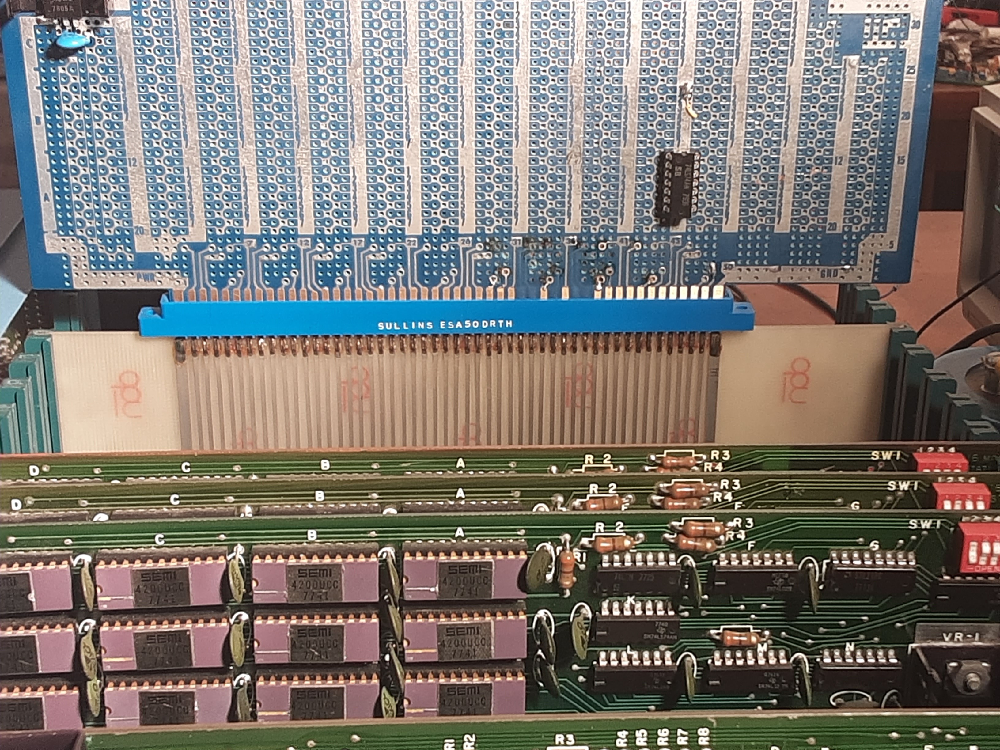
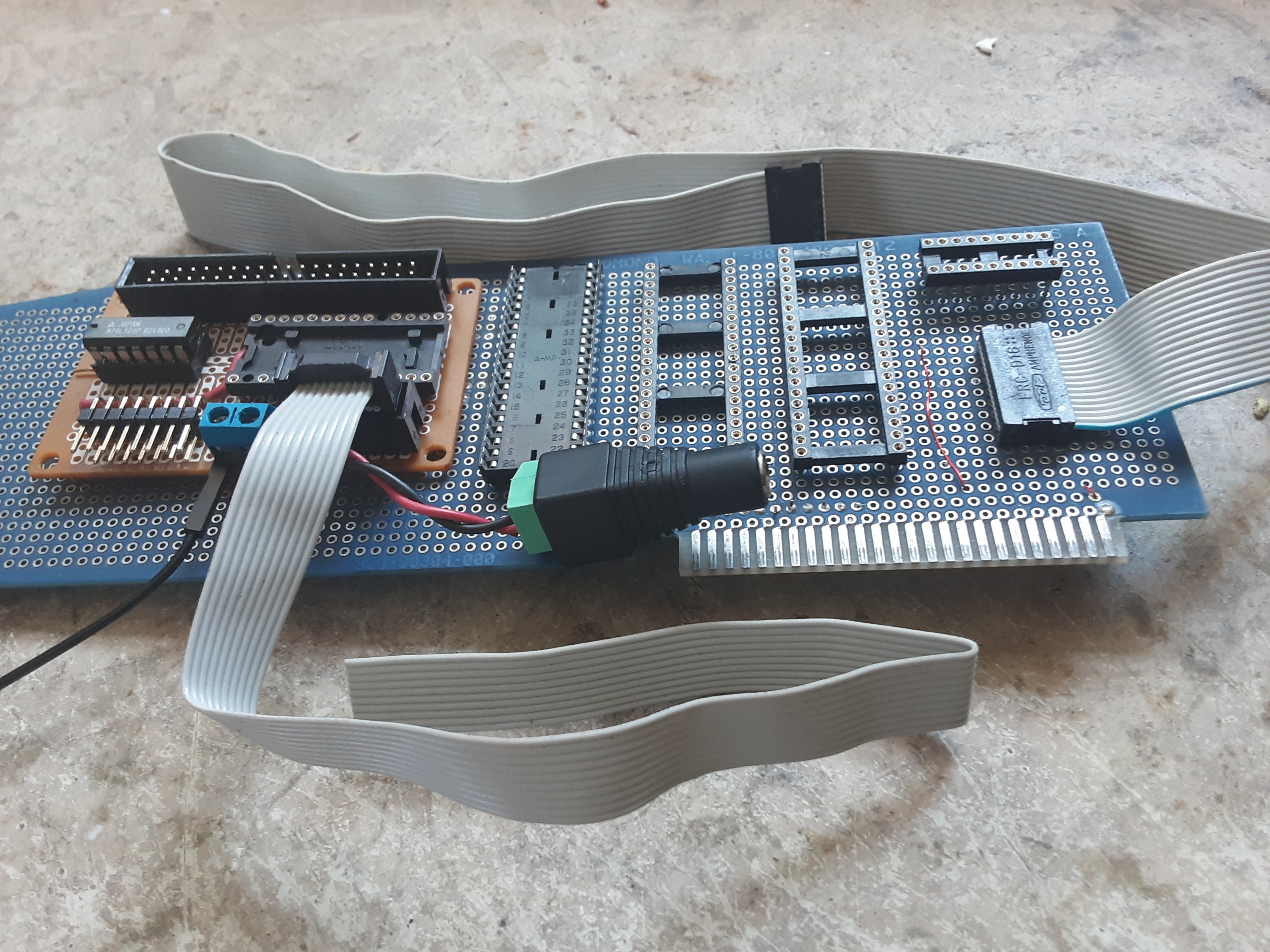
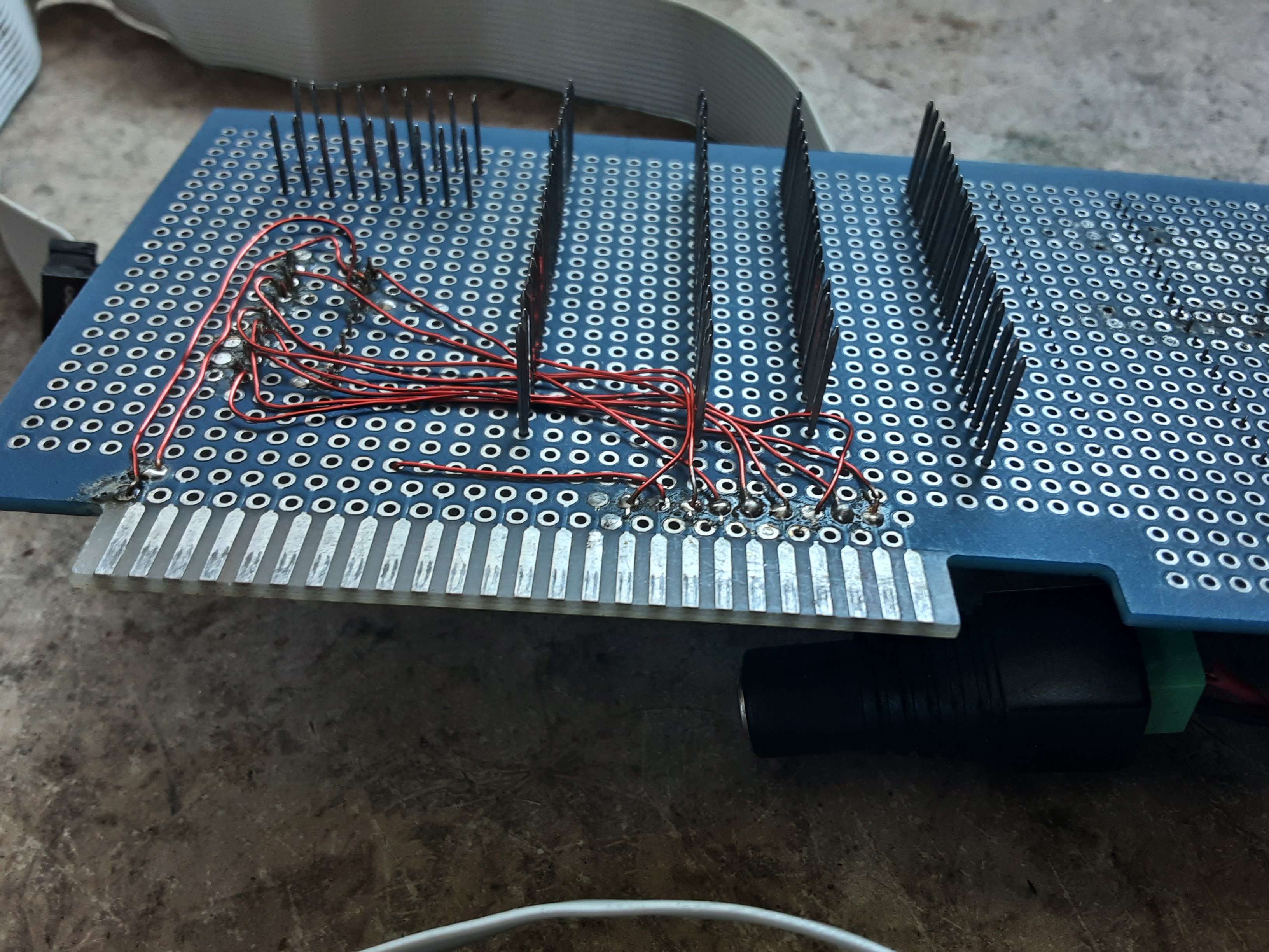
04/17/2023 at 05:22 • 0 commentsEven though this ancient S-100 prototyping board has seen better days, as can be seen by the missing pads on some of the address and data lines, it can still be put to good use. Here I am grabbing the 2 MHz system clock on pin 49 and sending it to a 74LS74 which is being used as a divide by four.
![]()
And thus we can obtain, by very simple means, a nice, clean, stable 500 kHz derived clock signal which can be passed on to one of the 6850 UARTs(Hopefully), so that when that particular UART is run in 16x mode, it will be able to send and receive signals at the MIDI data rate of 31250 bps. At which point I should hopefully have no problem getting the Altair to stream MIDI data in, and thereupon use it to make the front panel LEDs blink in interesting ways; like with MIDI data in real-time.
![]()
Of course, this might be fun to build ... eventually.
![]()
-
Trying out the latest version of KiCAD
04/13/2023 at 07:49 • 0 commentsThis is so totally preliminary, but why not?
![]()
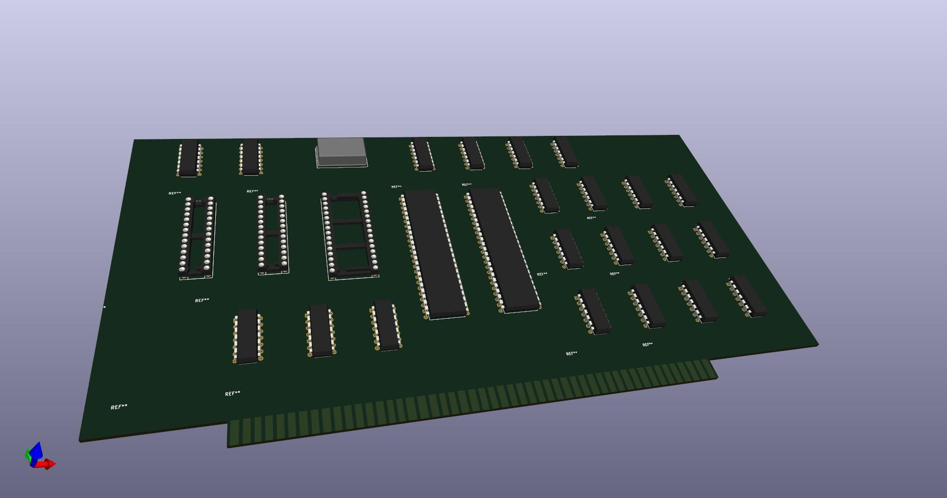
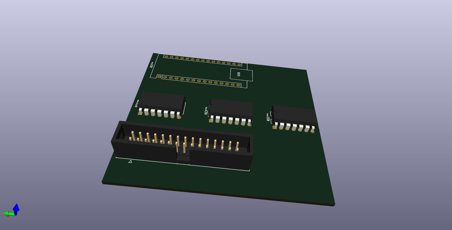
Well, this is going to take a while; but wow! O.K., sure. Why not? I know I am kind of old school about this sort of thing. So I thought I specified a 15-pin IDC connector, and it gave me a connector with 2 rows of 15 pins, and now I realize that maybe what I really want is the connector that has two rows of eight pins. It also placed the Arduino module 180 rotated 180 degrees from how I would want it. This is going to take a while.
After about an hour of fiddling around.
![]()
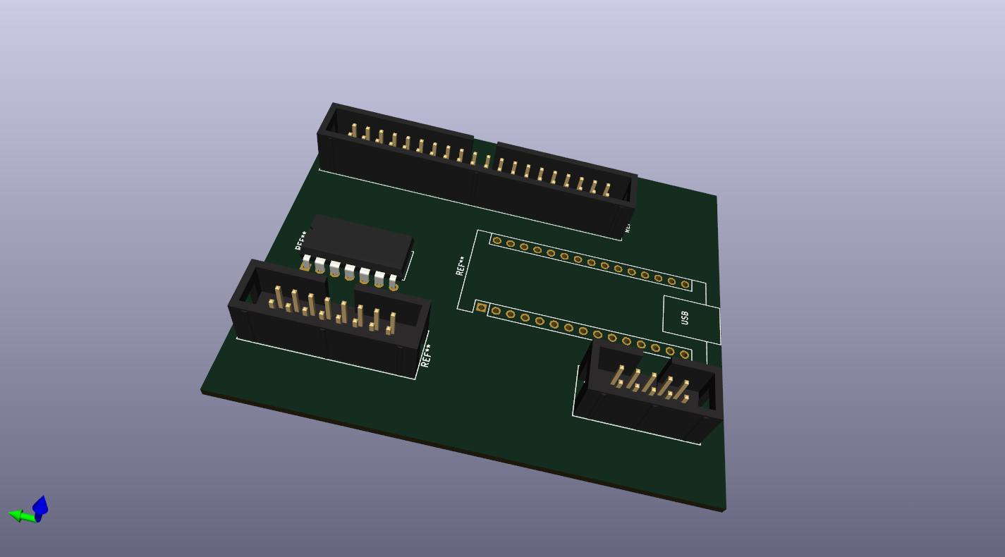
I noticed of course that the KiCAD software numbers the pins on the IDC connectors differently from how they are numbered on the DB-15 connector, which I will explain further at some point.
In the meantime, once upon a VERY long time ago, I actually made my own "sound card" for my Apple II+, by creating a very simple, but working data bus grabber that I could plug into any available Apple II slot. Then I ran the ribbon cable to some proto-board where I put together a simple D-A converter which used a 74LS374, IIRC, along with some resistors in a variation of the typical R-R2 configuration, to in turn implement the D-A part. This was done in such a way as to allow for the selection of either 4-bit stereo, or if the two output channels were tied together with a hand-selected resistor, I could have 8-bit stereo, Then I created wavetables in BASIC and saved the wave files to a floppy disk so that I could then play back pre-recorded "samples", as it were by using the BLOAD DOS call to load the samples, which were usually 256 bytes in length, and which could be played by an appropriate CALL to the hand-assembled "driver" which would output at 25,600 samples/second. And it just simply "worked", and probably would still work except for the fact that my II+ has keyboard issues, and although I also have an Apple IIe motherboard, I don't have a keyboard or case for that one at all.
Yet in any case, here is how the "universal I/O" concept could come together. Maybe I rip apart my much beloved Apple II bus grabber from days gone by and build my "new and improved" universal I/O module so that I get EXACTLY the features that I want and NEED for the II+, and possibly the IIe, and all of the rest, as previously discussed.
![]()
Learning how to do everything in KiCAD is going to be a bit of work, but the results are going to turn out so much nicer than trying to do this the old-fashioned way.
![]()
So, even though this actually works, I think I will end up with a strong preference for the new and improved method. Even if it can be quite a bit of fun to just simply sit down with a bag full of old parts, and test fit this, or that, here or there while trying to figure out "how the busses" are going to route when all gets said and done. Maybe throw in a Propeller chip for that Apple II, to get some VGA mode, but then there is a 3.3-volt vs. 5-volt issue, and whether to use proper MOSFET-based level shifters or just latches and resistors. Now if I join the "surface-mount" bandwagon, then a lot of that stuff becomes a lot easier to work in, whether it is resistors, FETs, latches, etc., even though that totally messes up the "retro-feel" of things, there are some nice payoffs in terms of making the best use of board real estate, and of course, staying within the power budget - since and Apple II, or a Commodore 64 for that matter, is much more constrained than a full-size Altair, (with it's 18 AMP power transformer), for that matter.
Yet I found a Z80-style dual bidirectional parallel port chip, which might turn out to be useful. Let's suppose that I use it on the Apple II side of things while letting an Arduino handle all of the control lines. Given that it REALLY is possible to just simply connect up a 74LS374 directly to the data bus, slot enable and write lines, and get something that works like a "port", on the one hand, then maybe the Apple II could connect to the "port" side, and the "bus" side would go to so digital pins on the Arduino side, that is to say - which would help "stretch" the Arduino pin count, allowing for the addition of something else.
Not sure how that would work out, but I think that there are some designs floating around that have used a Propeller as an MMU, or such when connected to either a Z-80 or maybe even an 8 Mhz 6502; yet I suspect that that would require something more like the P2 chip, instead of the P1, that is, if I wanted to let a real 65C02 "think" that the P2 chip is actually RAM, while at the same time, letting the P2 generate Apple II graphics, etc., and so that the Apple II is really only needed for access to the floppy drives, and the SCSI based hard drive.
Realistically, this seems pretty far-reaching, yet it seems doable. Right now I am totally happy with the fact that I have access to MIDI data and PS2 data, on an "actual" board, that WILL evolve into a device that can be made to "commercial specifications", and with working software.
But the Apple II, will have to wait - I think I want to get back to working on the Altair.
-
Ground Control To Major Tom
04/12/2023 at 18:02 • 0 commentsAs discussed earlier, MIDI signals are able to be sent and received from the board, so now I am working on adding a PS2 keyboard interface option. This particular IBM keyboard seems to work just fine, without having to do any communications on "wake up" before it will talk to an external device. However, it did suffer from breakage of the original mini-DIN connector, many years ago, and rather than try to repair it at the time, I simply went out and bought another one. Just like nearly everyone else in our modern throw-away society, where if you had to pay someone to fix something, it all too often will cost more than a new one. Well, for now, maybe I will go ahead and put a DB9 connector on the keyboard since there is actually a standard for that, and then I am also adding a connection to my MIDI interface dongle, which is starting to look like it could turn into a mini-Altair in its own right.
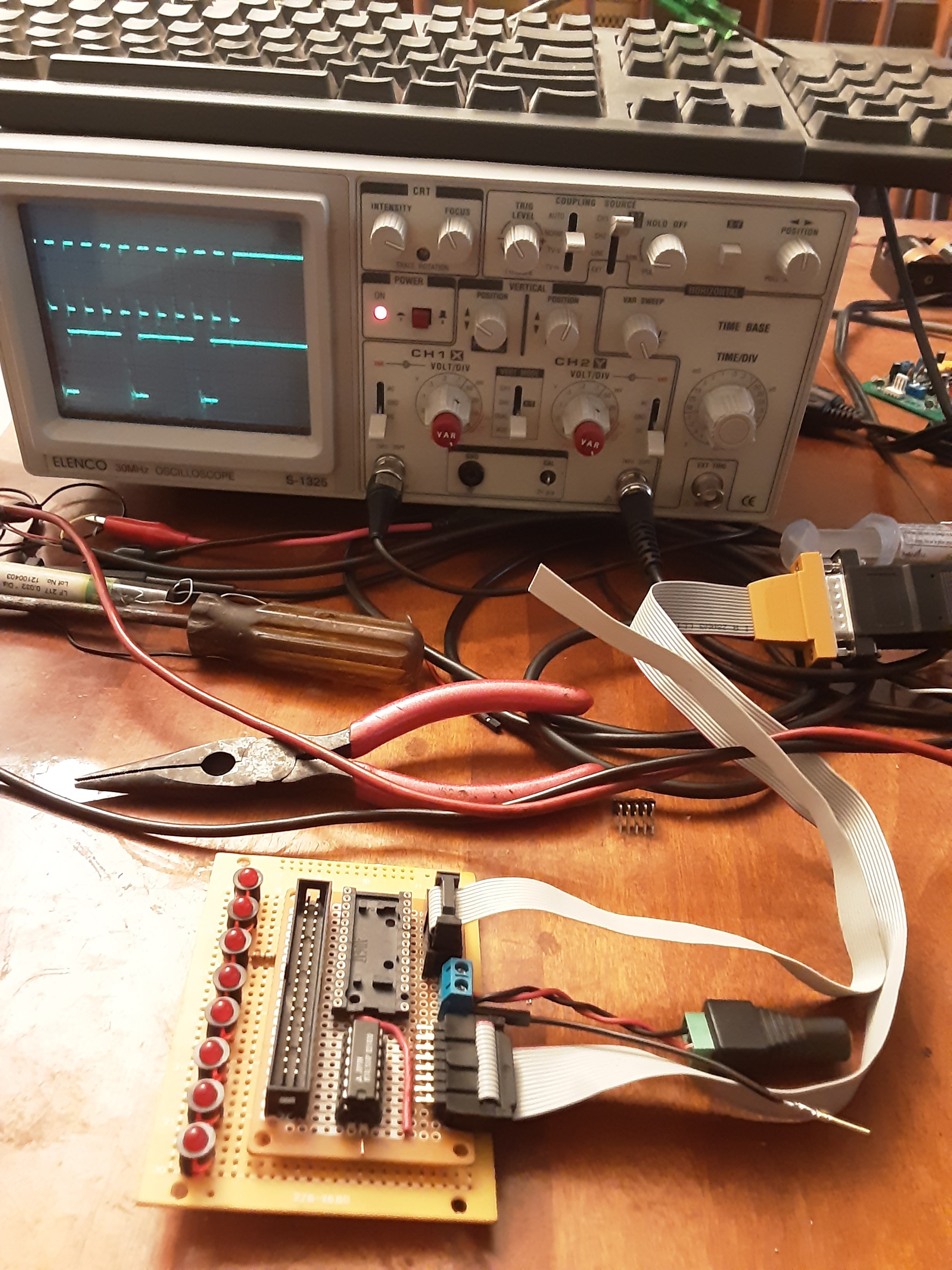
![]()
For now, the LED board is incomplete, and does "nothing", but at least the interface board is sending +5V to the MIDI cable and getting MIDI data back, with the PS2 interface to be added next. This will greatly simplify testing - if I decide to go ahead and connect it, using jumper wires, to an Arduino 2560. Of course, as I noticed just yesterday, the "Arduino Every", might turn out to be the ideal path to take for this particular device.
Yet, a bunch of stuff comes to mind. While on the one hand, there are other Altair emulators out there, those, for the most part, tend to emulate the features of the 8800A front panel, leaving out some otherwise very interesting, and well as potentially useful features of the 8800B. In particular, the 8800B version of the Altair, has some front panel switches that do things like "load and/or display the contents of the accumulator", as well as "reading and/or writing to specified I/O" ports.
Now I really don't want to go full Monty on this, with a design that might somehow display the contents of ALL the CPU registers, on row after row of blinking lights, just like the old UNIVAC display consoles that Irwin Allen repurposed, well, you know, in "Lost In Space", and "The Time Tunnel", and I think even in the basement of the "Towering Inferno." Now imagine that one - a computer-controlled building? Now, who would have thought of that? Then there was the time that Starbuck and Apollo had to infiltrate a Cylon Base Star so that they could blow up the Base Star's control center. I think that that one was a two-part episode, from the original series, entitled "The Living Legend". Lots of blinking lights, and worth checking out.
-
Interfacing the PS/2 Keyboard to the Altair?
04/11/2023 at 23:31 • 0 commentsNow that I am getting MIDI data with an actual piece of hardware, I am considering adding a PS2-compatible interface to some unused area of board real estate, for use of course with the Altair, when I get the MIDI sequencer software up and running in some sort of "stand-alone" mode.
![]()
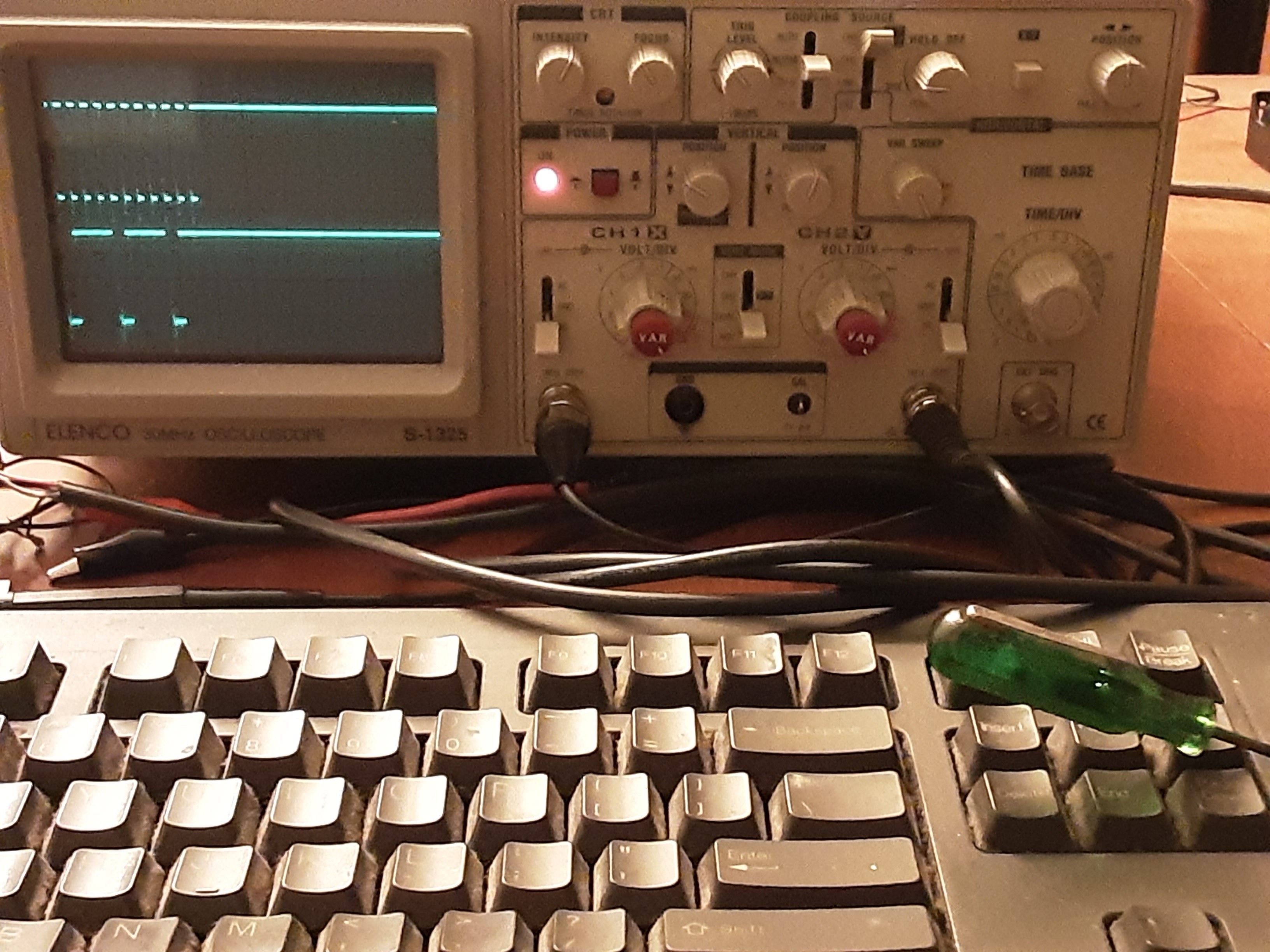
Now what we are seeing here is what this particular IBM keyboard just so happens to put out, when I jam the "Num Lock" key, which contrary to what you might have heard, is processed just like any other key. The difference between CAPS LOCK, and NUM lock, from other keys, therefore, is in how the PC responds when those keys are pressed, and that is by responding with some signals that tell the keyboard to turn certain lights on and off. Now if we don't implement the bi-directional part of the protocol, and in effect only let the keyboard do the talking, then it appears that the keyboard is giving us eleven clock pulses for every key press, or repeated messages in case of s "stuck" key, as seen here; that is - along with the data which is on the data line. That's it! Oh, and of course mapping the IBM key codes back to ASCII, which is easily done in software.
Now this suggests to me that MAYBE I should try my hand at PS2 keyboard decoding using one of the available UARTs on my Altair 2SIO serial board, which of course right now has a fried baud rate generator chip, that I will have to find a replacement for, or else I will have to fabricate something custom, which I am also contemplating - in any case, since MIDI runs at 31250 bits/second, and that would require a 500 kHz UART clock, which is quite easily done by dividing the 2 Mhz Altair system clock by four with a 74HCT74, or else a 74HCT163.
Unfortunately, right now I only have one serial board (with two ports), so I will have to think of something else, if I want the Altair to support direct keyboard input, MIDI I/O, and have a PC connected via a USB dongle.
One of the nice things about the Parallax Propeller P1 chip is that it is available in a through-hole 40-pin version, so it is possible to contemplate designing an all-new board that at least looks like it could have been made in the late '70s, or early '80s.
So there is a method to some of the madness after all, and that is because of the principle of "design" reuse. Thus I have "built something" so far that could evolve into a Pi hat or a stand-alone protocol converter, or maybe it could become a Commodore64 compatible cartridge, or maybe I could also have a PS2 converter for my Apple II, or maybe it could be a traditional Arduino form factor shield.
-
What I don't like about Arduino
04/11/2023 at 07:16 • 0 comments![]()
Here we have a general concept, of something that could be accomplished. Let's suppose that I have a custom board fabricated for my MIDI interface, which I built earlier today, using a combination of through-hole and surface mount components. In particular, what would happen if I used a surface mount version of the 328P, along with any level shifters, etc., that I might need for Propeller or Raspberry Pi interfacing?
So that could be used to make a stand-alone module. Then what if I leave some space on the board for a through-hole version of a 74HCT374 or something like that, which could then be inserted into a wire-wrap socket that could be soldered to the top board; but then the wire wrap pins could extend into the bottom board, where maybe only the power pins, and or corner pins would need to be soldered, i.e., so as to make potential disassembly - not impossible, just in case. This technique would allow for the construction of separate modules, where one module might be an extremely compact and otherwise fully self-contained 6502 computer, with CPU, RAM, and ROM; while another module could be an external I/O module, and yet another might be part of a debugging system, with or without blinking lights.
![]()
Then in effect, we could build up four or more layer designs, by creating individual modules that would then communicate through a "back-plane" of sorts; which would allow for the creation of a "final board" design - that can then be custom ordered and built up according to the final "project integration" plan; and with a good expectation that it will just simply work, "right out of the box", the first time.
Now if you have ever tried to plug an Arduino module into a prototyping board; you know about the header spacing glitch; which also makes it impossible to place "shields" side by side on a regular perf board. Which makes it completely unsuited for professional work. Clearly, something better is needed.
![]()
Here we see how the external IO might eventually use a multi-layer board to integrate with a larger system.
Well, in any case; I have reached the point, now that I have a way of getting MIDI signals in a board-friendly format so that I can consider the possibility of continuing with the real Altair MIDI project. Or is it going to be an Apple II MIDI project? Or will it be a Raspberry Pi MIDI dongle? Maybe it will turn into a MIDI everywhere micro-sequencer! Oh and let's not forget the time code. Yeah, time code. Gotta have time code, in some form or fashion.
Then again some of the newer Arduino stuff, like the Arduino Every, are looking fairly attractive, and I think that I just might be able to find a place to sneak in a pair of 15-pin headers. Yeah, so I download the latest datasheet for the Arduino Every, and it says something like "revised" on 4/11/2023.
![]()
When did they say that that was? Hmmm.
-
The Unicorn is in the Garden
04/11/2023 at 03:35 • 0 comments![]()
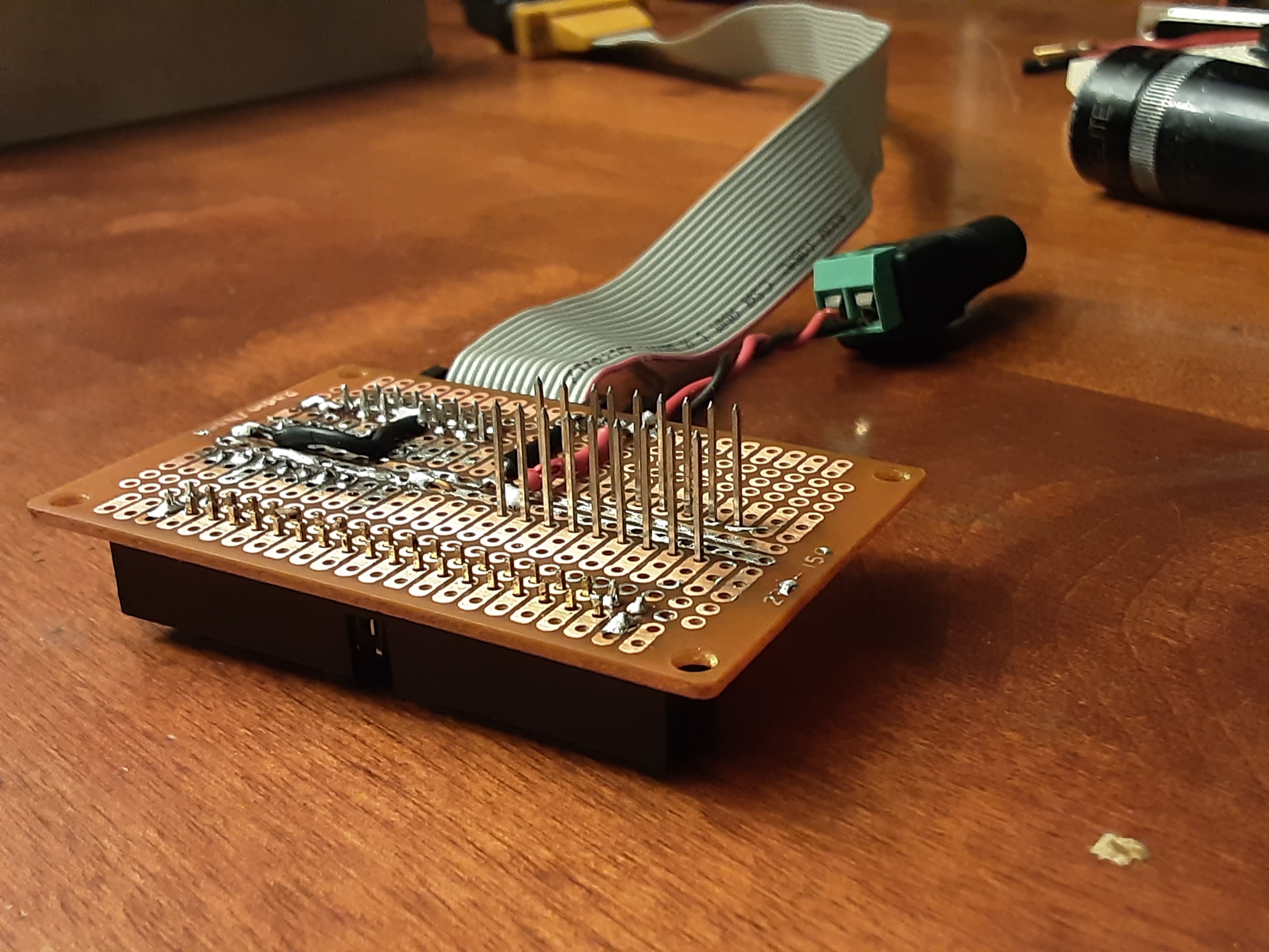
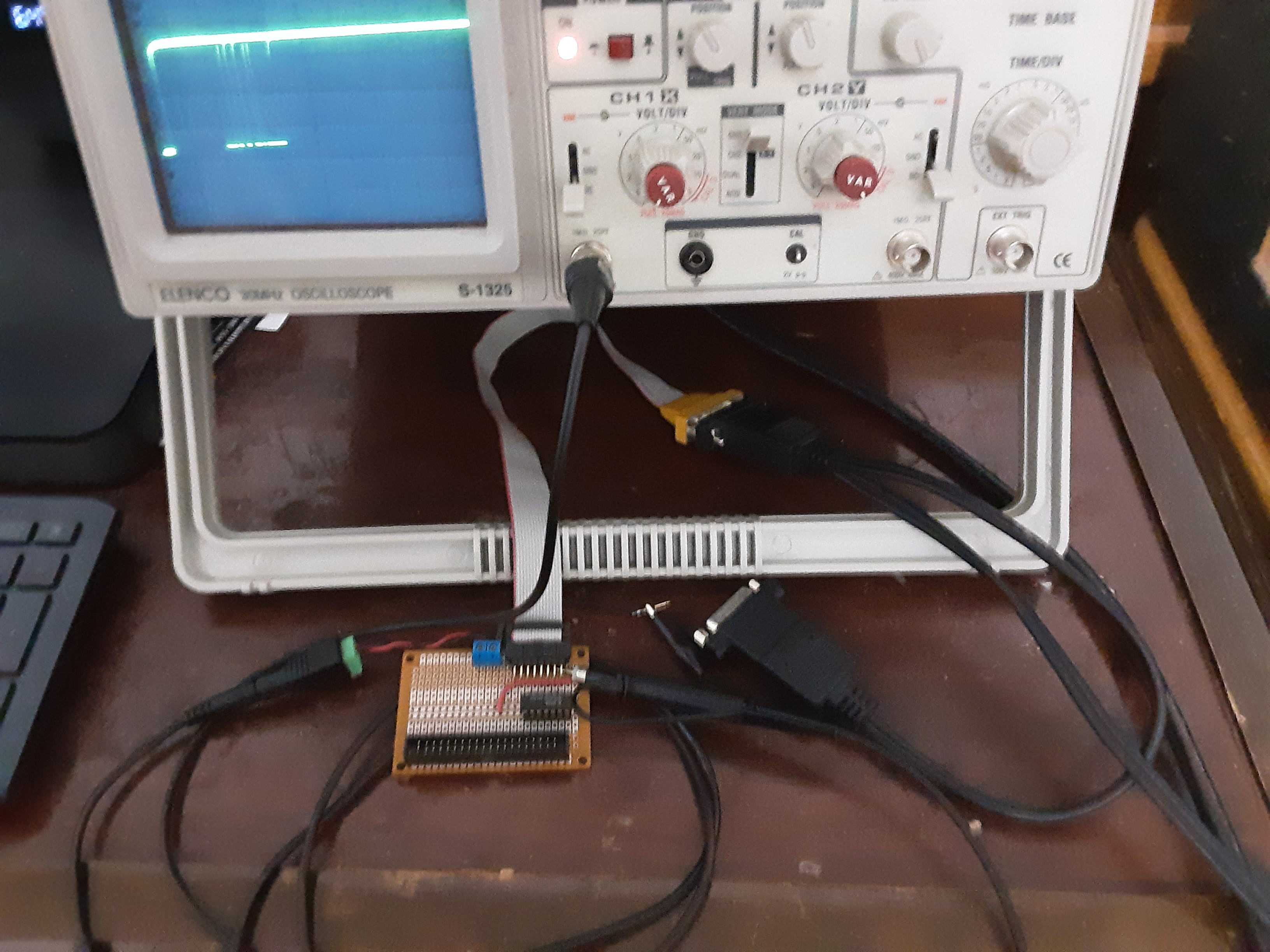
Started working on a dongle to connect the Sound Blaster MIDI cable to the Altair, or perhaps a Raspberry Pi, or else an Arduino - or perhaps it can be made to work with "all of the above." Here we are receiving some MIDI data from a Yamaha keyboard which is playing some material in demo mode. I scavenged a DB-15 female connector to IDC connector via ribbon cable from an old PC, that probably went to the recycler years ago, and that is how the Sound Blaster MIDI cable normally connects to the game port of a PC, that is if it still has a traditional game port. Added some IDC header pins and other goodies to some perf board, and presto, "instant" MIDI to "whatever" dongle, well, hopefully soon enough. Now as far as the Sound Blaster-compatible MIDI cables go, that part is pretty simple to wire up. Apparently, pins 4 and 5 are connected to the ground, then +5 volts should connect to pin 8, and that provides the power to some internal circuitry that is built into the cable assembly. Finally, MIDI data from a remote device will appear on pin 15, whereas pin 12 can be used to send MIDI data, which will need to be clocked at 31250 bits/second.
-
OK Then, Let's actually build SOMETHING.
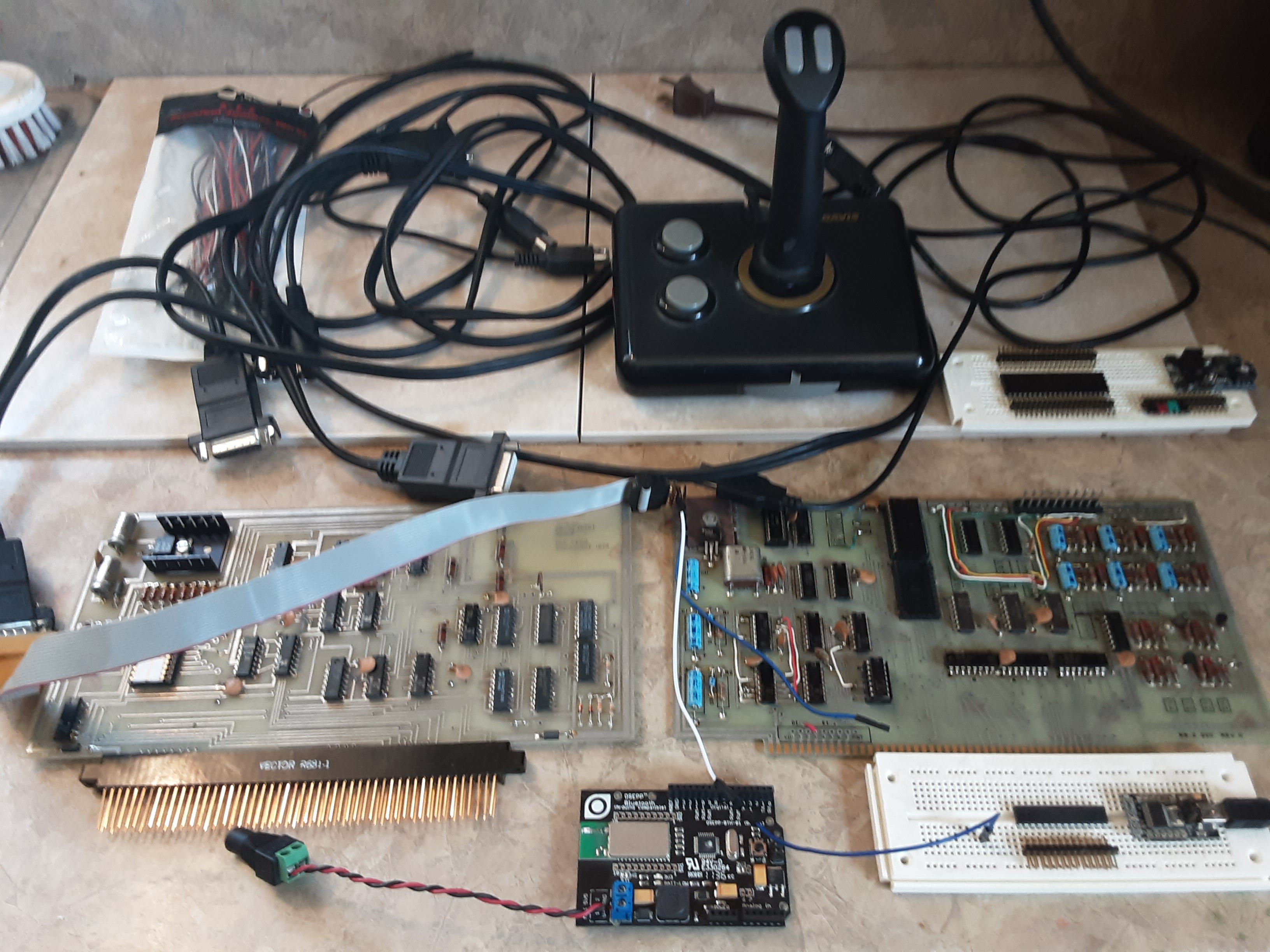
04/06/2023 at 20:13 • 0 commentsSome stuff that might actually turn out to be useful
![]()
If you have access to a genuine Altair or a full-size replica, that would be awesome - but fortunately, it is not a requirement. That is because Altair emulators can be run on any Arduino. However, I haven't looked into whether an Arduino can handle the 31250 bps data rate of standard MIDI AND still talk to another device over a USB dongle at the same time. If it all works out well, hopefully, it will turn out to be possible to turn a bare 328P chip, without the Arduino base into a full-fledged MPU-401 compatible sequencer, that just might be able to run "stand-alone" or while tethered to an attached PC. Or there is the Z-80 route. Of course, if you want to try the "real Altair" route, then it will be necessary to obtain a vectored interrupt board, in addition to a board with hopefully at least two working UARTS.
Now if you can lay your hands on one of those game-port MIDI cables that came with every Soundblaster ever sold, back in the day, then you are also way ahead of the game, as far as that part of the project goes, and that is because those cables usually have the required optoisolators built into the cable, which saves us some work. An old standard PC joystick might be fun to mess around with also. So get busy scavenging your junk drawer.
![]()
Then on the software side, it would also be nice to have something that runs on the PC side that just might make, well, whatever hardware we end up using, actually do something interesting, like playing music or running a new and improved version of "Lunar Lander", or whatever. The fact that the MIDI protocol is sometimes used in robotics, whether in an industrial capacity or in some entertainment-animatronics applications, should not go unnoticed, either. Thus whether we end up with a musical device that might be tethered to a DAW, or whether it is capable of running standalone as a true sequencer, remains to be seen. Yet that is also one of the goals of this project.
Of course, I want to get it up and running on the Altair, and have some kind of application running on THAT machine, just for the sake of the coolness factor. These machines are certainly capable of doing much more than just playing "kill the bit", or running BASIC as a demo. So some assembly language work will need to be done, for the custom stuff that is yet to be accomplished. Yet nonetheless, for convenience, most of the development will be done in C/C++ on a PC, with an eye toward writing compatible code that will also, eventually compile and run on any of a number of microcontrollers.
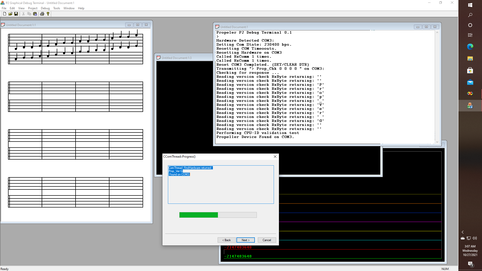
Now as far as instant gratification is concerned, reading data from a USB to RS-232/TTL convertor at one speed, such as 231 kbps, and then repeating them at another speed, such as the 31250 MIDI rate, seems like a simple enough task. Hopefully, it is also one of those things that can be done pretty much as an afternoon project. That is, once all of the hardware is hooked up, and the toolchain is configured. Since like I said, that part will mostly be just reading some data, and then writing it, either in a loop or ideally with interrupts. Yet, once we get to that point, all kinds of new, interesting, and hopefully fun possibilities should emerge. Like sequencing, or using pitch detection software to control a vocoder, which would be a separate device (they exist). Yet, we will be doing this stuff using the Arduino or Altair-based MIDI, and that will give us some very fine-grained control of things that we can't otherwise do with traditional (read: commercial) DAW software - especially in a live environment.
Of course, on the side of economic factors, last time I checked, a 328P microcontroller can be hand for just a few dollars, that is, without going the fully Arduino route - which suggests to me something that might be very important in an educational environment, and that is the cost per student, as far aa lab-fees and the like are concerned. You see, while some chips like the Propeller or the Pi can be reprogrammed, ideally, an "infinite" number of times, when you take into account the fact that the Atmega chips rely on a build-in EEPROM that can "only" be flashed about 10,000 or so times, imagine in an educational environment, where 100's of students are sharing the same equipment, and where each student might be doing 100's of compile-test-verify cycles every lab period, and I don't really know therefore, just how quickly they will wear out if they are constantly being reprogrammed. So maybe in an entry-level lab, it would make sense to have the required oscilloscopes, logic analyzers, power supplies, etc., be provided by the institution, while at the same time, the 328Ps might be considered "consumables", that could be paid for out of "lab fees", or otherwise "provided" for students to "keep" at the end of the course., according to the type of program.
So here is an interesting question: How many people really need another clock or calculator, or lawn sprinkler controller, even though those things are very doable? Then again, how many people would want to have some pre-programmed riffs that could be uploaded into their favorite drum machine?
O.K., then, let's get back to bit-bashing.
Project Seven
Bringing deep learning to platforms such as the Raspberry Pi, Parallax P2, or maybe an Altair 8800 for general robotics and other things.
 glgorman